Next Issue
Volume 3, September
Previous Issue
Volume 3, March


Int. J. Turbomach. Propuls. Power, Volume 3, Issue 2 (June 2018) – 9 articles

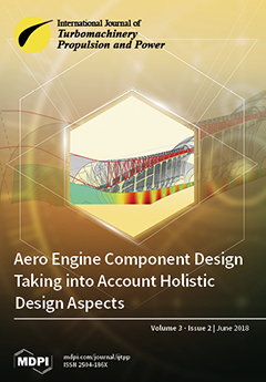
Cover Story (view full-size image): Aero engine design is based on the development of isolated components with fixed interface parameters and little or no feedback from other components. However, to guarantee consistent information transfer between all components and to fully exploit the optimization potential, holistic design goals should be pursued within a coupled, multi-objective, cooperative optimization framework through proper parametrization and optimization strategies.View Paper here.
  • Issues are regarded as officially published after their release is announced to the table of contents alert mailing list.
  • You may sign up for e-mail alerts to receive table of contents of newly released issues.
  • PDF is the official format for papers published in both, html and pdf forms. To view the papers in pdf format, click on the "PDF Full-text" link, and use the free Adobe Reader to open them.
Order results
Result details
Select all
Export citation of selected articles as:
18 pages, 22734 KiB  
Article
Methods for Controlling Gas Turbine Casing Flows During Engine Shutdown
by Andrew Pilkington, Budimir Rosic and Shigenari Horie
Int. J. Turbomach. Propuls. Power 2018, 3(2), 17; https://doi.org/10.3390/ijtpp3020017 - 12 Jun 2018
Cited by 3 | Viewed by 5763
Abstract
During the shutdown of a gas turbine, natural convection flows occur inside of the engine casing. These natural convection flows cause the top of the engine casing to cool more slowly than the bottom of the casing. This non-uniform cooling can cause the [...] Read more.
During the shutdown of a gas turbine, natural convection flows occur inside of the engine casing. These natural convection flows cause the top of the engine casing to cool more slowly than the bottom of the casing. This non-uniform cooling can cause the casing to distort, known as “cat-back” distortion. This distortion leads to reduced tip and seal clearances, which can cause rubbing and binding. In this study, two different methods for reducing the non-uniform casing heat transfer in an industrial gas turbine during shutdown were investigated. A baseline case with no active method for reducing the casing heat transfer was compared with purge and flow extraction methods. It was found that the new proposed extraction method improved the uniformity of the casing heat transfer during the initial shutdown period. Full article
Show Figures

Figure 1

20 pages, 10917 KiB  
Article
Experimental and Numerical Study of Transonic Cooled Turbine Blades
by Andrey Granovskiy, Vladimir Gribin and Nikolai Lomakin
Int. J. Turbomach. Propuls. Power 2018, 3(2), 16; https://doi.org/10.3390/ijtpp3020016 - 08 Jun 2018
Cited by 4 | Viewed by 3568
Abstract
State-of-the-art gas turbines (GT) operate at high temperatures that exceed the endurance limit of the material, and therefore the turbine components are cooled by the air taken from the compressor. The cooling provides a positive impact on the lifetime of GT but has [...] Read more.
State-of-the-art gas turbines (GT) operate at high temperatures that exceed the endurance limit of the material, and therefore the turbine components are cooled by the air taken from the compressor. The cooling provides a positive impact on the lifetime of GT but has a negative impact on its performance. In convection-cooled turbine blades the coolant is usually discharged through the trailing edge and leads to limitations on the minimal size of the trailing edge, thereby negatively affecting the losses. Moreover, the injection of cooling air in the turbine disturbs the main flow, and may lead to an additional increase in loss. Trailing edge loss is a significant part of the overall loss in modern gas turbines. This study comprises investigations of the unguided flow angle, the trailing edge shape, and cooling air injection through the trailing edge on the base pressure and profile losses in cooled blades. Some vane and blade cascades with different unguided turning angle and two shapes of trailing edges with and without coolant injection were studied both experimentally and numerically. This analysis provides a split of losses caused by different factors, and offers opportunities for efficiency and lifetime improvements of real engine designs/upgrades. In particular, it is shown that an increase in the unguided turning angle and the use of a round trailing edge result in a reduction of loss in case of a relatively thick trailing edge. Numerical investigation showed that an increase in the unguided turning angle at the initial transonic vane with a thick and blunt trailing edge, without a change in other basic geometric parameters, allowed for a significant reduction of the profile loss by about 3–4% at the exit Mach number M2is = 0.7–1.0. Experimental investigation of four cascades with cooling air injection into the base flow through the trailing edge allowed us to validate the fact that in blades with a low level of base pressure Cpb < −0.1 at m¯ = 0 a non-monotonic dependence of the change of losses against relative cooling air mass flow m¯ is observed. Firstly, the cooling air injection into wake increases base pressure and decreases losses; then the losses start to increase with increasing cooling mass flow due to the interaction between the main flow and the cooling air (mixing losses) and, finally, due to the cooling mass flow increase and momentum increase losses are decreased. In blades with an increased level of the base pressure coefficient Cpb ≥ −0.1 at m¯ = 0 the cooling air injection results in an increase in losses right from the beginning of the injection and then, according to the cooling mass flow increase and momentum rise, losses decrease. It is also shown that injection through the trailing edge slot parallel to the main flow leads to a neutral loss impact and even a loss reduction in the subsonic range and a loss increase in the supersonic range of exit Mach numbers. Full article
Show Figures

Figure 1

13 pages, 534 KiB  
Article
Impact of Front- and Rear-Stage High Pressure Compressor Deterioration on Jet Engine Performance
by Gerald Reitz and Jens Friedrichs
Int. J. Turbomach. Propuls. Power 2018, 3(2), 15; https://doi.org/10.3390/ijtpp3020015 - 23 May 2018
Cited by 3 | Viewed by 3776
Abstract
Current civil aviation is characterized by rising cost and competitive pressure, which is partly passed to the MRO (Maintenance, Repair and Overhaul) companies. To improve the maintenance, condition-based maintenance is established, which is characterized by tailored maintenance actions for each part of the [...] Read more.
Current civil aviation is characterized by rising cost and competitive pressure, which is partly passed to the MRO (Maintenance, Repair and Overhaul) companies. To improve the maintenance, condition-based maintenance is established, which is characterized by tailored maintenance actions for each part of the jet engine, depending on the individual engine history and operating conditions. Thereby, prediction models help engineers to authorize maintenance actions as effectively as possible. This paper will help to improve these prediction models. Therefore, the influence of specific deterioration of a high pressure compressor (HPC) to jet engine performance parameters such as exhaust gas temperature (EGT) and specific fuel consumption (SFC) will be investigated. For this purpose, computational fluid dynamic (CFD) calculations of deteriorated HPC geometries are carried out and serve as a basis to scale the reference HPC performance characteristics to deteriorated ones. To evaluate the changes in performance parameters, a modular performance synthesis model is set up. In this model, the HPC map is exchanged with deteriorated ones. As a result, the influence of geometric deviations to the design intent can be determined, and the MRO companies are able to focus on the most relevant sections of the compressor blading. Full article
Show Figures

Figure 1

13 pages, 1262 KiB  
Article
Sensitivity Analysis of BLISK Airfoil Wear
by Andreas Kellersmann, Gerald Reitz and Jens Friedrichs
Int. J. Turbomach. Propuls. Power 2018, 3(2), 14; https://doi.org/10.3390/ijtpp3020014 - 16 May 2018
Viewed by 3491
Abstract
The decreasing performance of jet engines during operation is a major concern for airlines and maintenance companies. Among other effects, the erosion of high-pressure compressor (HPC) blades is a critical one and leads to a changed aerodynamic behavior, and therefore to a change [...] Read more.
The decreasing performance of jet engines during operation is a major concern for airlines and maintenance companies. Among other effects, the erosion of high-pressure compressor (HPC) blades is a critical one and leads to a changed aerodynamic behavior, and therefore to a change in performance. The maintenance of BLISKs (blade-integrated-disks) is especially challenging because the blade arrangement cannot be changed and individual blades cannot be replaced. Thus, coupled deteriorated blades have a complex aerodynamic behavior which can have a stronger influence on compressor performance than a conventional HPC. To ensure effective maintenance for BLISKs, the impact of coupled misshaped blades are the key factor. The present study addresses these effects on the aerodynamic performance of a first-stage BLISK of a high-pressure compressor. Therefore, a design of experiments (DoE) is done to identify the geometric properties which lead to a reduction in performance. It is shown that the effect of coupled variances is dependent on the operating point. Based on the DoE analysis, the thickness-related parameters, the stagger angle, and the max. profile camber as coupled parameters are identified as the most important parameters for all operating points. Full article
Show Figures

Figure 1

17 pages, 10648 KiB  
Article
Experimental Characterization of Unsteady Forces Triggered by Cavitation on a Centrifugal Pump
by Dario Valentini, Giovanni Pace, Angelo Pasini, Ruzbeh Hadavandi and Luca D’Agostino
Int. J. Turbomach. Propuls. Power 2018, 3(2), 13; https://doi.org/10.3390/ijtpp3020013 - 07 May 2018
Cited by 4 | Viewed by 4775
Abstract
The paper presents an experimental campaign aimed at the characterization of the relationship between cavitation-induced instabilities and forces acting on the shaft, relevant to space application turbopumps. The experiments have been carried out on a six-bladed unshrouded centrifugal turbopump. Pressure fluctuations are analyzed [...] Read more.
The paper presents an experimental campaign aimed at the characterization of the relationship between cavitation-induced instabilities and forces acting on the shaft, relevant to space application turbopumps. The experiments have been carried out on a six-bladed unshrouded centrifugal turbopump. Pressure fluctuations are analyzed in their frequency content for understanding the instability nature (axial, rotating) and their main characteristics (e.g., amplitude, rotating direction). The spectral analysis of the force components highlights a strong relationship of the z-component (along the rotating axis) with axial instabilities. On the other hand, rotating cavitation may involve force oscillations along all the three components leading to unwanted and dangerous fluctuating unbalances perpendicular to the rotating axis. Full article
Show Figures

Figure 1

16 pages, 3086 KiB  
Article
Component-Specific Preliminary Engine Design Taking into Account Holistic Design Aspects
by Marco Hendler, Michael Lockan, Dieter Bestle and Peter Flassig
Int. J. Turbomach. Propuls. Power 2018, 3(2), 12; https://doi.org/10.3390/ijtpp3020012 - 27 Apr 2018
Cited by 6 | Viewed by 3527
Abstract
Efficient aero engine operation requires not only optimized components like compressor, combustor, and turbine, but also an optimal balance between these components. Therefore, a holistic coupled optimization of the whole engine involving all relevant components would be advisable. Due to its high complexity [...] Read more.
Efficient aero engine operation requires not only optimized components like compressor, combustor, and turbine, but also an optimal balance between these components. Therefore, a holistic coupled optimization of the whole engine involving all relevant components would be advisable. Due to its high complexity and wide variety of design parameters, however, such an approach is not feasible, which is why today’s aero engine design process is typically split into different component-specific optimization sub-processes. To guarantee the final functionality, components are coupled by fixed aerodynamic and thermodynamic interface parameters predefined by simplified performance calculations early in the design process and held constant for all further design steps. In order not to miss the optimization potential of variable interface parameters and the unlimited design space on higher-fidelity design levels, different coupling and optimization strategies are investigated and demonstrated for a reduced compressor-combustor test case problem by use of 1D and 2D aero design tools. The new holistic design approach enables an exchange of information between components on a higher-fidelity design level than just simple thermodynamic equations, as well as the persecution of global engine design objectives like efficiency or emissions, and provides better results than separated component design with fixed interfaces. Full article
Show Figures

Figure 1

13 pages, 1777 KiB  
Article
Vortex Structure and Kinematics of Encased Axial Turbomachines
by Peter F. Pelz, Paul Taubert and Ferdinand-J. Cloos
Int. J. Turbomach. Propuls. Power 2018, 3(2), 11; https://doi.org/10.3390/ijtpp3020011 - 27 Apr 2018
Viewed by 3805
Abstract
This paper models the kinematics of the vortex system of an encased axial turbomachine at part load and overload applying analytical methods. Thus far, the influence of the casing and the tip clearance on the kinematics have been solved separately. The vortex system [...] Read more.
This paper models the kinematics of the vortex system of an encased axial turbomachine at part load and overload applying analytical methods. Thus far, the influence of the casing and the tip clearance on the kinematics have been solved separately. The vortex system is composed of a hub, bound and tip vortices. For the nominal operating point φ φ opt and negligible induction, the tip vortices transform into a screw. For part load operation φ 0 the tip vortices wind up to a vortex ring, i.e., the pitch of the screw vanishes. The vortex ring itself is generated by bound vortices rotating at the angular frequency Ω . The hub vortex induces a velocity on the vortex ring causing a rotation at the sub-synchronous frequency Ω ind = 0.5 Ω . Besides, the vortex ring itself induces an axial velocity. Superimposed with the axial main flow this results in a stagnation point at the tube wall. This stagnation point may wrongly be interpreted as dynamic induced wall stall. For overload operation φ the vortex system of the turbomachine forms a horseshoe, i.e., the pitch of the screw becomes infinite. Both hub and tip vortices are semi-infinite, straight vortex filaments. The tip vortices rotate against the rotating direction of the turbomachine due to the induction of the hub vortex yielding the induced frequency Ω ind = 0.5 Ω / s with the tip clearance s. Full article
Show Figures

Figure 1

17 pages, 10489 KiB  
Article
The Influence of Different Wake Profiles on Losses in a Low Pressure Turbine Cascade
by Florian Hammer, Neil D. Sandham and Richard D. Sandberg
Int. J. Turbomach. Propuls. Power 2018, 3(2), 10; https://doi.org/10.3390/ijtpp3020010 - 17 Apr 2018
Cited by 15 | Viewed by 4810
Abstract
Large eddy simulations were carried out in order to investigate the influence of unsteady incoming wakes with different profiles on the loss mechanisms of the high lift T106Alinear low-pressure turbine (LPT) cascade. Bars placed upstream of the LPT blade were set into rotation [...] Read more.
Large eddy simulations were carried out in order to investigate the influence of unsteady incoming wakes with different profiles on the loss mechanisms of the high lift T106Alinear low-pressure turbine (LPT) cascade. Bars placed upstream of the LPT blade were set into rotation around their axis, thus generating circulation, as well as asymmetrical wake profiles. Three different rotation rates were simulated, yielding different wake parameters that were then compared to an actual turbine blade wake profile. Whereas the commonly-used non-rotating bars generated wakes with turbulent kinetic energy levels several times higher than that of an actual blade wake, the case with counter-clockwise rotation led to more rapid wake mixing. All three wakes were able to trigger boundary layer transition and thus intermittently prevent separation on the suction surface. However, the weaker the wakes, the larger and longer lasting the separation bubbles became, and an increase in profile losses could be observed. Interestingly, the configuration with the weakest wake and the largest separation bubble resulted in a reduction of the overall LPT loss. Full article
Show Figures

Figure 1

18 pages, 29444 KiB  
Article
Investigation on Thrust and Moment Coefficients of a Centrifugal Turbomachine
by Bo Hu, Dieter Brillert, Hans Josef Dohmen and Friedrich-Karl Benra
Int. J. Turbomach. Propuls. Power 2018, 3(2), 9; https://doi.org/10.3390/ijtpp3020009 - 11 Apr 2018
Cited by 11 | Viewed by 4953
Abstract
In radial pumps and turbines, the centrifugal through-flow in both the front and the back chambers is quite common. It strongly impacts the core swirl ratio, pressure distribution, axial thrust and frictional torque. In order to investigate these relationships experimentally, a test rig [...] Read more.
In radial pumps and turbines, the centrifugal through-flow in both the front and the back chambers is quite common. It strongly impacts the core swirl ratio, pressure distribution, axial thrust and frictional torque. In order to investigate these relationships experimentally, a test rig was designed at the University of Duisburg-Essen and described in this paper. Based on both the experimental and numerical results, correlations are determined to predict the impacts of the centrifugal through-flow on the core swirl ratio, the thrust coefficient and the moment coefficient. Two correlations respectively are determined to associate the core swirl ratio with the local through-flow coefficient for both Batchelor type flow and Stewartson type flow. The correlations describing the thrust coefficient and the moment coefficient in a rotor-stator cavity with centripetal through-flow (Hu et al., 2017) are modified for the case of centrifugal through-flow. The Daily and Nece diagram distinguishing between different flow regimes in rotor-stator cavities is extended with a through-flow coordinate into 3D. The achieved results provide a comprehensive data base which is intended to support the calculation of axial thrust and moment coefficients during the design process of radial pumps and turbines in a more accurate manner. Full article
Show Figures

Figure 1

Previous Issue
Next Issue
Back to TopTop