1. Introduction
Aero engine development is associated with both time and financial effort. To minimize development costs as well as risk, engine projects are often realized as divided design processes in cooperation with other companies (joint venture) or as redesign based on established aero engines [
1]. A major advantage of dividing tasks is the applicability of a modular design strategy, in which each component (fan, compressor, combustor, and turbine) is designed independently from the others [
2,
3]. The component-based consideration reduces the high complexity of the overall system and splits the analysis effort into more simple tasks fitting to the limited computational power available [
4]. For the same reasons, component design is split into different design phases with an increasing degree of fidelity—starting with a simple and fast performance calculation and leading up to a time-consuming 3D unsteady flow simulation [
5,
6,
7]. To guarantee the final functionality after assembling all individually designed modules, interfaces between the components have to be pre-determined in such a sequential, multi-stage design process. Typically, they are defined early during the performance calculation based on rather simple thermodynamic models and remain constant in later higher-fidelity design phases.
Hence, a holistic analysis of the overall engine is realized only in the very first design step. The subsequent, higher-fidelity autonomous component design processes in the more detailed design phase interpret these prescribed interfaces as fixed bounds and try to find their best results within these bounds. As the performance calculation in the first step does not consider geometric engine specifications, it may be expected that the interface state selection based on low-fidelity performance models is not necessarily optimal, which finally leads to non-optimal overall engine performance. Instead, the early fixing of interface states results in an unnecessary limitation of the design space for higher-fidelity and more precise component design tools, which would be able to better evaluate the effect of the variations of the interface states and adapt them to find an overall optimal engine. This raises the question of how much potential is lost in current engine design projects by keeping the interface states fixed instead of allowing for modification by higher-fidelity tools during the component design process.
Some benefits of a holistic design strategy have been shown in [
8,
9], where decoupled design problems with complex interfaces are solved for aircrafts. For aero engines, holistic design is typically only performed with low-fidelity strategies like scaling based on thermodynamic cycle information [
10,
11,
12]. In the current paper, an alternative design approach is presented, in which components of a two-shaft aero engine are designed simultaneously by using design tools with higher fidelity than just a performance calculation and in which variable interfaces are controlled by optimizing whole engine targets. For simplification, the concept is described along a test case consisting of only two core engine modules, the high pressure compressor (C) and the combustor (B), where analysis is based on 1D Meanline and 2D Throughflow Rolls-Royce in-house codes for the compressor and a response surface model for the combustor. The proposed concept, however, is not restricted to this situation but may also be fully based on adaptive response surfaces as described in [
13] or include computational fluid dynamics (CFD) analysis. It should be noted that the design case focuses on engine design point conditions so that the main performance requirements like work level and shaft speed, as well as external boundary conditions like inlet airflow, overall compressor pressure ratio, and environmental parameters, are held constant.
The remainder of the paper is organized as follows: In
Section 2, an extended compressor part is optimized as reference solution by following the concept in [
5] with fixed interface conditions to the downstream combustor component. In order to enable a coupling of compressor design with the combustor feedback and allow whole engine optimization, an isolated design problem for the combustor is formulated in
Section 3. For holistic design, two different approaches are described in
Section 4, which are then applied to the test case and compared in
Section 5.
2. Compressor Design Process
The compressor module of a two-shaft aero engine consists of three main parts, as shown in
Figure 1. The S-duct (SD) as first subcomponent transfers the incoming flow of the low pressure system (fan) to the faster rotating, high-pressure compressor (HPC) moving on a lower radius. Downstream of the S-duct, the bladed annulus section of the (HPC) feeds power to the fluid for compression, and the annulus cross section decreases substantially. Finally, the short diffusor section (PD) reduces the flow speed and directs the air mass flow into the combustion chamber.
To design the complete compressor section from S-duct inlet to diffusor outlet, a two-step approach is used here based on a combination of 1D Meanline and 2D Throughflow calculations to allow for the testing of a huge number of configurations. However, also higher-fidelity calculations as 3D CFD may be incorporated depending on limitations of computational resources. The objective of the compressor design sub-process is to search for a geometry configuration with best polytropic compressor efficiency
relating compressor pressure ratio
to total inlet and outlet temperatures
and
by specific heat
[
2].
In the first design step, the optimizer tries to find a valid compressor part from inlet guide vane (IGV) to outlet guide vane (OGV), i.e., in the HPC section, with the help of the 1D Meanline code only. Therefore, different design parameters summarized in design vector
concerning annulus shape, stage pressure ratio, exit flow angles, and axial chord lengths are modified. The flow evaluation takes place only at the annulus midline and ignores adjoining upstream and downstream compressor components; compare [
5].
To receive more detailed information, a 2D streamline curvature analysis called Throughflow is executed for each valid Meanline compressor design. This analysis starts from the flow information of the preceding 1D calculation and is able to evaluate the complete compressor geometry including S-duct and diffusor as shown in
Figure 1. Here, flow information is determined in radial direction on different streamlines. The final information of the Throughflow calculation could then be used to generate aerofoils [
14] and to build a 3D compressor geometry model for executing stress analyses or a multistage 3D-CFD.
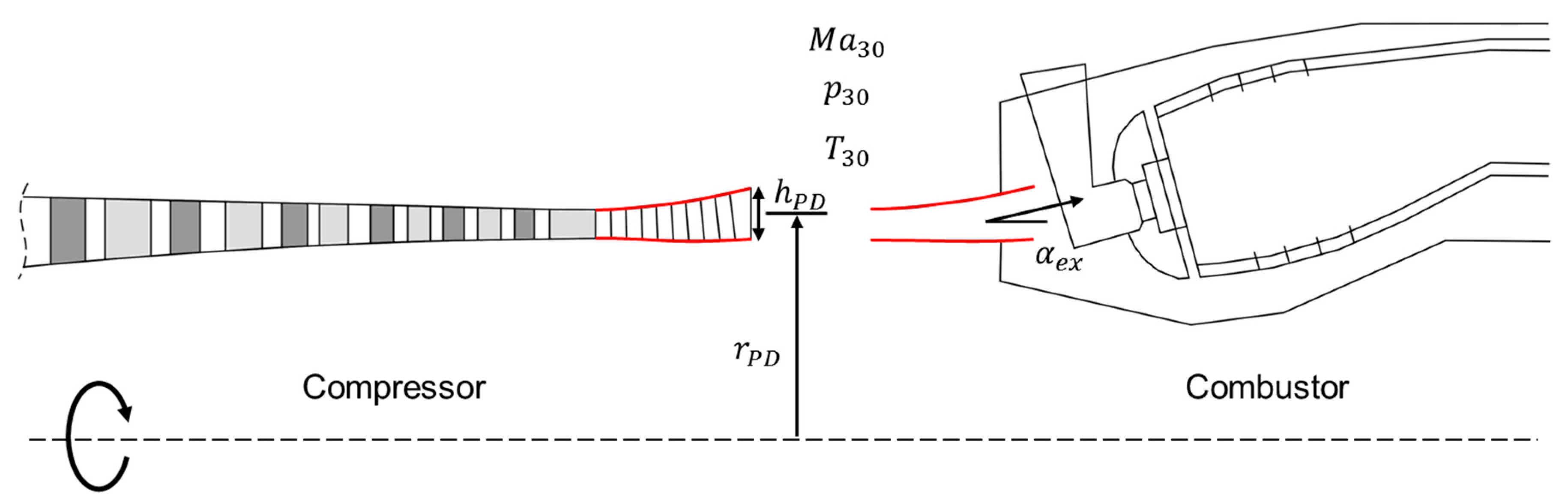
Only with such an embedded compressor calculation taking S-duct and diffusor into account, the relevant compressor interface values at the diffusor exit position can be determined properly. Relevant interface parameters between compressor and the downstream combustor component are exit flow angle
, exit flow Mach number
, exit temperature
, and exit pressure
summarized in coupling vector
; see also
Figure 2. They result from the compressor flow analysis, which is why their compliance with combustor specifications cannot be guaranteed in advance, but must be enforced during the optimization process. This can be achieved either in a classical way by equating them with prescribed values from the performance calculation, or by using them as flexible interface variables in a global engine optimization problem as proposed in
Section 4. The same applies to the geometric parameters
in
Figure 2, which have to be identical for both components (i.e., compressor exit and combustor inlet).
To ensure a valid compressor design, various constraints limiting diffusion factors, de Haller numbers, stage works, inlet Mach numbers, or surge margin according to [
5] have to be considered. All these compressor-specific limits are summarized in inequality constraints
, which leads to the single objective compressor optimization problem
with lower and upper bounds
and
on the design vector
defined in the following.
The biggest influence on finding a valid compressor geometry can be attributed to design parameters effecting the inner and outer annulus contour represented by two B-spline curves. They are based on a reference compressor contour, which, in a first design step, is scaled to the inlet and outlet of the actual compressor, and then the scaled control points are additionally modified within user-defined margins by the optimizer, see, e.g., lower annulus contour in
Figure 1. To ensure the highest possible level of flexibility independently of the number of control points used for the contour lines, their variation is controlled by separate perturbation splines for hub (
) and tip (
) with a constant number of control points being lower than those of the reference contour. An example for such an HPC hub section perturbation spline is given in the lower part of
Figure 1. Control points of the annulus splines are not modified directly by the optimizer, but rather by changes of the perturbation splines whose control points are actively modified as part of the design vector
in Equation (2). In order to reduce the dimension of the design space, perturbation information is only applied in radial direction by
of the hub control points, where axial variations may be applied analogously if more general modifications of the compressor geometry are desired.
Similar procedures are applied to S-duct and diffusor, where the three parts of the contour line are treated separately to allow for more individual design flexibility [
15]. To guarantee an overall continuous perturbation spline, the transition control points to neighboring compressor parts are identical on both sides, respectively. The outer perturbation control points of the diffusor perturbation section are set to meet the predefined coordinates, which are either fixed or set by the interface variables.
Special attention is payed to the properties of the diffusor part: it acts as adapter between compressor and combustor component with the task of converting dynamic pressure into static pressure and ensuring a low-loss inflow into the combustor section [
16]. The exit flow of this component has significant influence on the flow of the combustor dome and on the air distribution inside the combustor. The large number of free contour variables in this section allows for the adjustment of different exit flow angles, even for constant diffusor exit coordinates.
The presented parametrization strategy allows for the introduction of an additional design parameter, which varies the influential length ratio
between the bladed compressor part
and the diffusor
, where the overall compressor length
is fixed, as well as the swan neck duct length
. This complicates the optimization effort on the one hand, but increases the design space on the other. The additional parameter may help to find a valid compressor design faster or to find more efficient design configurations. Some relevant geometric changes caused by perturbation of some design parameters in vector
are demonstrated in
Figure 3, causing geometry modifications of annulus outline, diffusor slope, length ratio, radial exit height, or axial chord lengths.
For fixed coupling conditions
,
, as this would be the case in classical isolated component design processes, the extended compressor design process creates more realistic flow results than optimization of the bladed part only.
Figure 4 displays a 2D flow field of an optimized compressor geometry, in which the absolute Mach number in the S-duct geometry is distributed rather homogenously with no local peaks; the bladed section shows the typically desired intensive stressing of the hub profiles of the first rotor stations. The consideration of 36 compressor specific constraints in
ensures the aspired, radially uniform outflow at the last high pressure compressor stator (i.e., OGV), a minimum annulus height for minimal flow blockage, and a diffusor geometry preventing flow separation. The last mentioned property is evaluated by a quality factor checking the inlet to outlet area ratio of the diffusor and comparing it to empirically determined limits.
3. Combustor Design Problem
An isolated component optimization such as the example presented above cannot be guaranteed to receive best overall engine performance, because the optimization potential there lies in the modification of local design parameters only. To expand the design diversity and to find a globally optimal aero engine configuration, it is necessary to take into account the requirements of neighboring components. For the current test case, combustor design aspects will be incorporated into the compressor design process.
A simple process extension by neighboring component analyses will not be sufficient because of the fixed interfaces. For example, if the compressor parameters are modified and the combustor module is only analyzed without changing its local design parameters, the combustor will always contribute in the same way to the overall engine behavior. Therefore, interface values have to be considered as flexible and adaptable for higher-fidelity design processes, as this allows for a direct estimation of the compressor effects on the combustor module and finally on the overall design objectives. In contrast, for the current test case without turbine, the combustor exit station has to be considered as a global system boundary where aerodynamic and geometric parameters are regarded as constraints. The geometric information at the combustor-turbine interface is scaled from a valid reference design. Other important combustor operating parameters (e.g., fuel mass flow and relight sizing) are also given by the performance calculation and held constant.
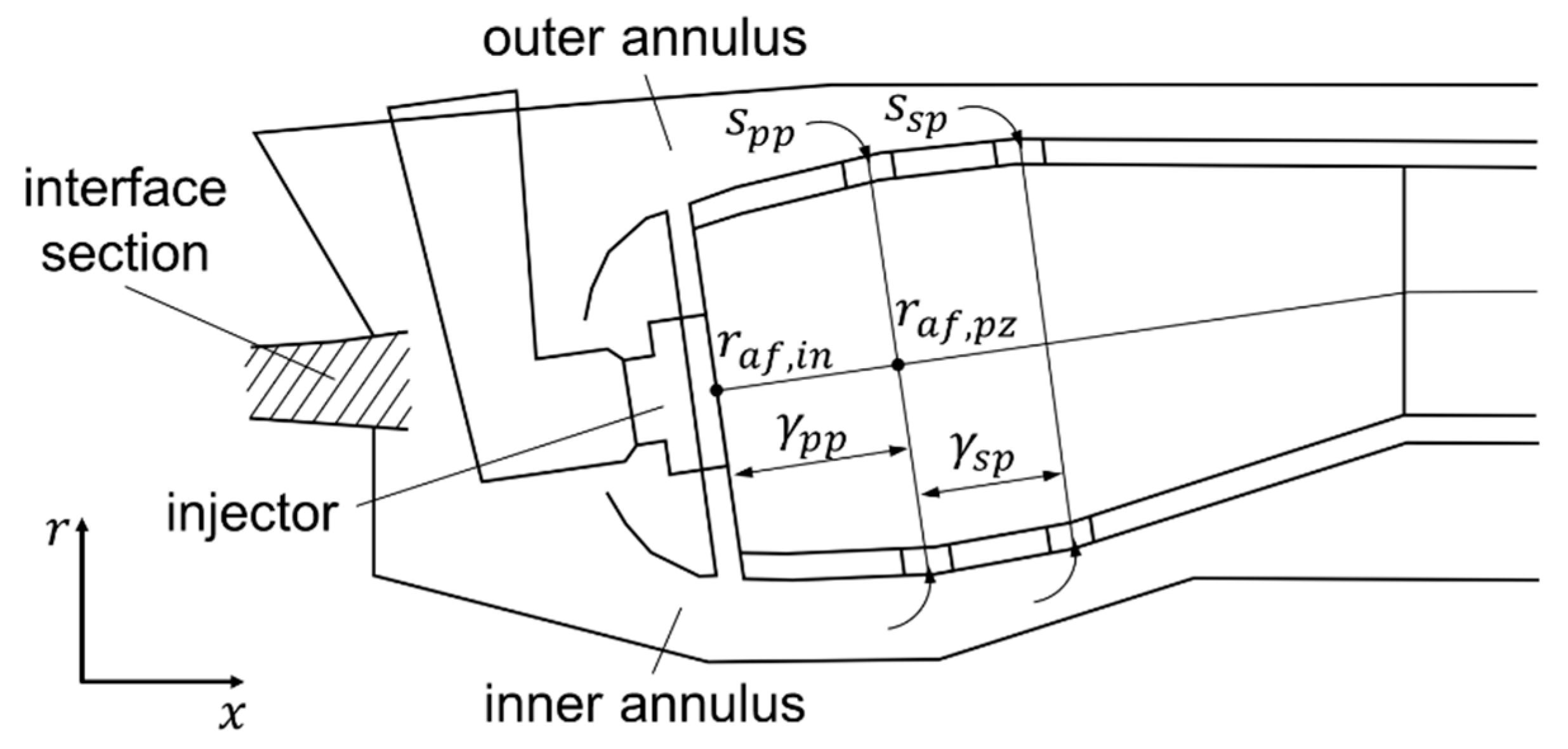
Because of the significant influence of the compressor-combustor interface parameters on the combustor performance, a parametrized combustor design process is needed that is able to recalculate the combustor geometry and internal flow in every iteration loop. A fast state-of-the-art preliminary Rolls-Royce inhouse design tool is used that fulfills all necessary requirements regarding accuracy and flexibility. The tool uses internal design rules and correlations to provide all relevant aerodynamic flow parameters, as well as a 2D combustor geometry, as shown in
Figure 5. Key element of the tool is an internal flow solver adjusting the main geometric components within the given boundary conditions until, e.g., combustion stability, relight sizing, and desired Mach number distributions are fulfilled. Main objectives for the combustor design are to minimize the emissions and to maximize its efficiency
based on empirical correlations in which different aerodynamic and geometric combustor parameters are taken into account. The main emissions of carbon monoxide
, nitrogen oxides
, and unburned hydrocarbons
are summarized in the emission index
which equals the sum of the single emission values divided by the mass of injected fuel [
17]. In order to influence the combustor outline and to optimize the efficiency and emission index, flow settings concerning the internal air distribution will be varied. Relevant design parameters are the air-to-fuel-ratios at injector
and primary zone exit
, length of primary and secondary combustion zones represented by the relative position of the related mixing ports (
,
), and the style of the primary and secondary mixing ports (
,
) similar to [
18]. The air-to-fuel ratios are related to the local mass flows at the injector, as well as primary zone exit, and are normalized by the fuel mass flow. They are the driving parameters for the inner combustor air distribution.
For a constant fuel mass flow, the air-to-fuel ratios affect the air flow distribution between mass flow passing the injector and the one flowing through the outer and inner annulus, see
Figure 5. As already indicated, the position of the mixing ports is related to the length of the combustion zones. The length and volume of each combustion zone has a significant influence on the residence time of the air-fuel-mixture with a direct effect on the resulting emissions. For example, if the first mixing port is located further downstream, the hot primary zone is very distinctive, and the residence time is high. This favors the relight ability and the fuel burn-out, and reduces CO generation. But for lower NO
x emissions it would be better to have only a small primary section and to leave the hot zone as quickly as possible. Hence, with the variation of the mixing port position, the location can be defined where cooling air is fed, and also the kind of emissions that are generated can be defined.
The style of the mixing port defines the jet inclination angle and thus influences the jet penetration. Here, two different port styles can be selected, which are represented by logical parameters
,
. To get a plain mixing port style, which implicates a lower jet inclination angle,
must be selected. In contrast,
leads to a higher jet inclination angle. The final design vector results in
Because of the high influence of the zonal combustor volumes on emissions and efficiency, they are taken into account by three inequality constraints
during the design process based on internal design rules. The given constraints guarantee a combustor configuration which fulfills all International Civil Aviation Organization (ICAO) admission requirements. Thus, the isolated combustor optimization problem reads as
Due to the mixing port parameters in design vector
, Equation (5) is a mixed-variable optimization problem that requires special strategies. However, this may also be handled by a bound-and-cut type strategy, in which the optimizer works with continuous variables
instead of discrete variables
and
. For analyses, these real values are rounded as
to select the respective mixing port styles.
4. Holistic Design Strategy
The consideration of several components in a coupled design process implicates a number of advantages, but specific challenges as well. For instance, impacts on downstream components by local geometry variation in upstream components can be evaluated directly, and the findings gained can be applied in subsequent iteration loops. With regard to the present compressor-combustor test problem, not only the interface parameters will be exchanged, but also the complete diffusor annulus geometry is handed over from the compressor to the combustor. The diffusor geometry is considered in both design processes, because it is an integral part of both underlying sub-processes, i.e., the Throughflow solver for compressor analyses and the combustor design tool. Thus, the diffusor geometry is treated as an overlapping interface and exchanged to guarantee a consistent gas path geometry; otherwise the isolated compressor and combustor design processes would develop different diffusor interface sections independently from each other. The exchange of geometry information extends the design space and enables consideration of more design parameters like lengths modifications of the compressor subcomponents or unblocking of the radial interface coordinates by and . For the holistic design, the last hub and tip control points of the compressor perturbation spline are added as design variables to , and the previously used parameters and in at a specific transition point are replaced by the coordinates of the 2D hub and tip diffusor annulus contour. The transferred aerodynamic and geometric diffusor design information is used as pure input in the combustor component design process.
The geometry exchange between the two design processes impacts the performance prediction of both compressor and combustor. This would lead to a double-counting of the diffusor losses corrupting the overall efficiency. In order to avoid this corruption of an overall design criterion, the compressor efficiency value is read out directly behind the bladed part, i.e., at OGV exit, whereby the diffusor flow is not recognized in the compressor efficiency value but still for the compressor constraint calculation. However, through the extension the requirements and interests of different components must be combined. This leads to a multi-criterion optimization problem and a higher number of design parameters, resulting in a more complex problem definition and design task.
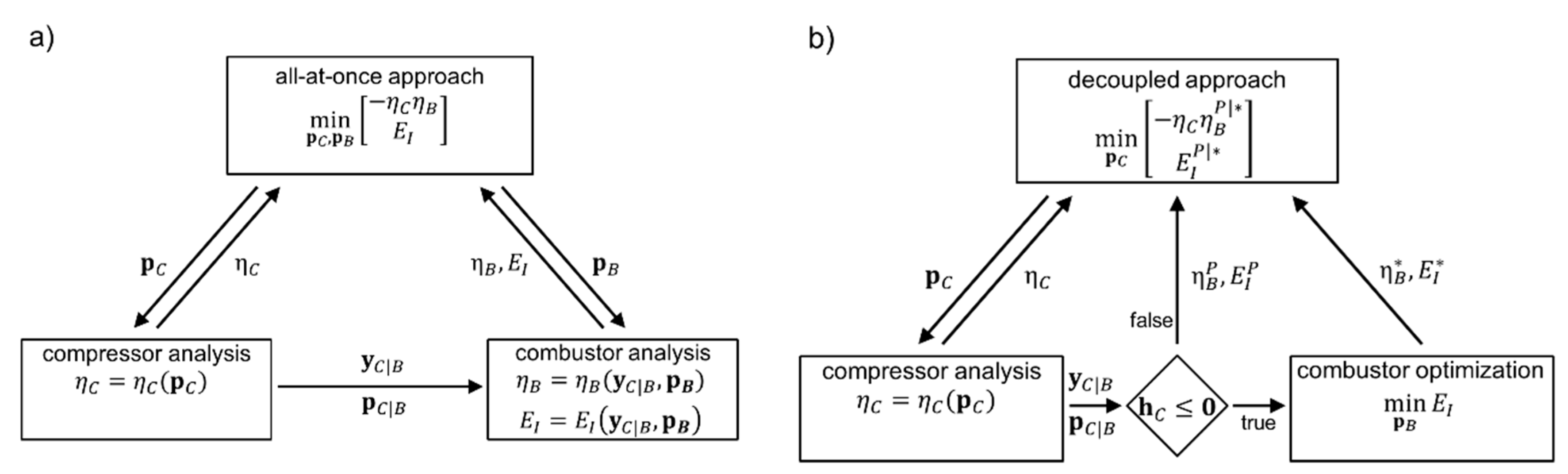
Two different solution strategies for coupling the two engine components will be investigated. The first design approach is an all-at-once strategy, in which both component design processes are integrated into a single optimization process and all design parameters are managed simultaneously by the overall optimizer,
Figure 6a. The sub-processes are executed sequentially, where the upstream compressor component is executed first to determine the input parameters
and
for the subsequent combustor component. Due to prediction limitations of the involved design tools, upstream coupling effects from the combustor onto the compressor, such as the pressure increase in the combustor dump region, are neglected here. However, if the design process is extended by higher-fidelity design tools, upstream flow information should be considered and evaluated as well. After execution of both analyses, the results are returned to the optimizer. The global design problem formulation combines Equations (2) and (5) and represents a multi-criterion optimization problem [
19] with design parameters
and constraint functions
. However, to reduce the number of global objectives, the component efficiencies are combined. For the present chained compressor-combustor system, the efficiency values may be multiplied to receive the overall efficiency
. This leads to the bi-criterion optimization problem
with interface quantities
determined by compressor analysis and used for combustor analysis. Lower and upper bounds for
are determined with regard to empirical knowledge to ensure feasible designs.
In order to reduce the number of design variables in the overall optimizer, a second design process is proposed with a separated combustor optimization,
Figure 6b. In contrast to the all-at-once approach, the global optimizer concentrates on the compressor optimization and varies the compressor design variables only. The combustor design process is not executed for every converged compressor optimization. Only if a compressor configuration fulfills all compressor constraints
and lies within prescribed interface bounds
, a subsequent combustor optimization is performed, which searches for an optimal combustor geometry for the given set of interface parameters
and
by varying local design parameters
.
To reduce the computational time of the combustor optimization according to problem (5), only a single-criterion optimization is executed. Since the combustor efficiency for the considered “cruise” flight cycle is very high and almost invariant, it is not considered as an objective anymore, but as a constraint with a lower bound
. All in all, this leads to the modified combustor optimization problem
However, the higher-level optimizer will receive both values, i.e., the optimal emission
and the associated combustor efficiency
, to calculate the overall efficiency and to evaluate the overall engine performance similar to the all-at-once approach. If no valid compressor design exists for a given set of parameters, penalty values
and
for the combustor objectives are returned. In summary, the system design problem
needs to be solved to obtain an overall optimal compressor with the decoupled optimization approach.
5. Results
To demonstrate the benefit of a holistic compressor-combustor design process and to investigate differences between the two proposed coupling strategies, three optimizations have been performed. The first one is a classical isolated compressor design according to
Section 2 with fixed values for interface quantities
,
and a subsequent compressor analysis to finally obtain reference values for overall efficiency
and emission
. The problem (2) is solved with the Covariance Matrix Adaptation Evolution Strategy (CMA-ES) [
20], and the obtained result is denoted as reference design
later on.
Subsequently, holistic design formulations (7) and (9) are solved, where, in contrast to reference design , the interface parameters and are not fixed but kept variable within defined ranges. This leads to an increased design space and offers completely new possibilities in the configuration and design of the individual components, as well as the interface section. The larger the range of the variables, the higher is the degree of variation.
For solving the all-at-once problem (7) represented in
Figure 6a, the multi-objective genetic AMGA (Archive-based Micro Genetic Algorithm) [
21] with the settings in
Table 1 is used. In total, 10,000 designs are evaluated. For the decoupled compressor-combustor design problem, also the AMGA is used with similar settings for the problem (9) represented by the upper box in
Figure 6b. In addition, the underlying combustor design problem (8) is solved with CMA-ES. The number of function evaluations for each CMA-ES search, which is executed only for valid compressor configurations, is set to 160 or 20 generations with a population size of 8 only. With these settings, sufficient convergence accuracy can be obtained with the help of the used tools.
In direct comparison of compressor and combustor design processes, a combustor analysis takes 20 times longer than the used compressor design evaluation. To reduce this execution time discrepancy for utilizing both design strategies in an efficient manner and to make them more attractive for industrial application, the time intensive combustor performance prediction is replaced by a response surface. A polynomial regression model of degree two is used to emulate effects of relevant combustor parameters, in which port style parameters are treated as continuous variables, but training of the response surface is performed with discrete values (6) only. The surrogate model is based on an initial Latin hypercube sampling [
22] with 300 design evaluations, which are generated before execution of the optimization. The use of this surrogate model leads to a significant reduction of the combustor evaluation response time by a factor of 400, see
Table 2.
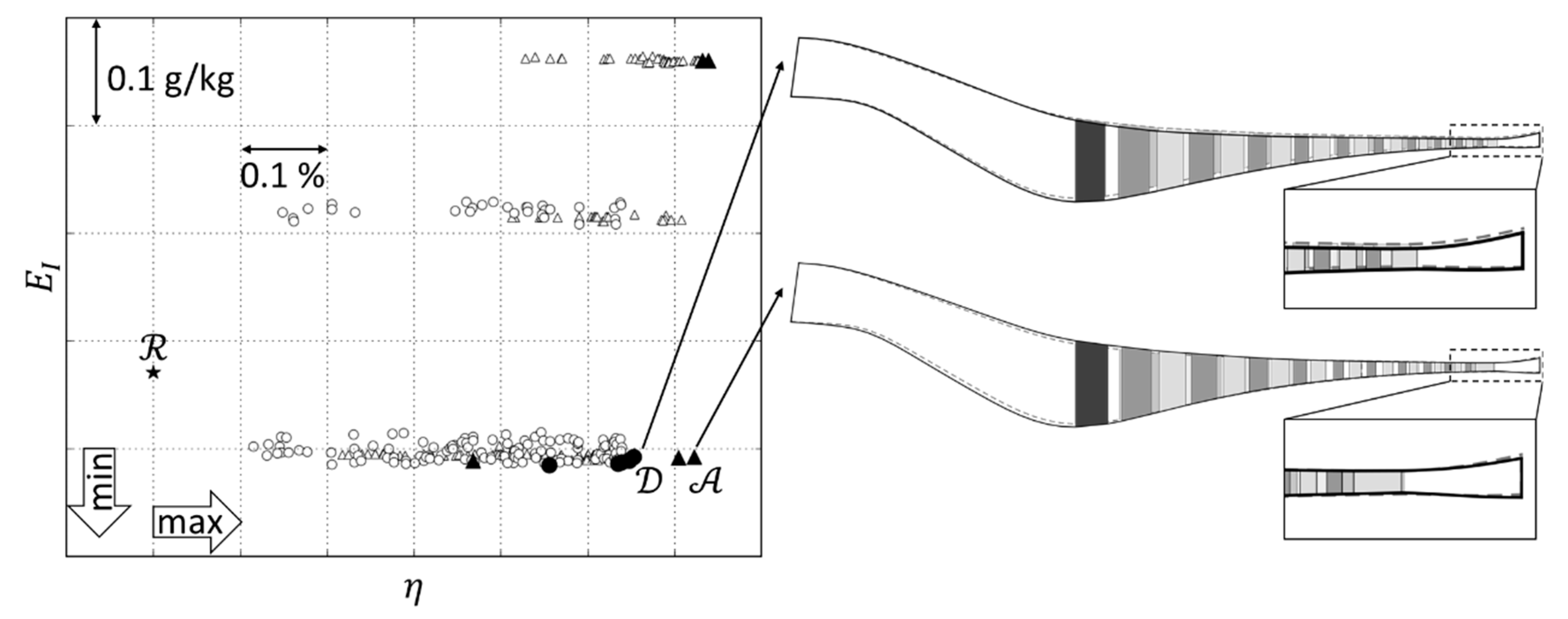
As can be seen in
Figure 7, both holistic optimization strategies yield non-dominated solutions (represented by black triangles and circles), which are better in both criteria compared to the reference design
obtained from isolated compressor optimization. However, also differences between the all-at-once approach and the decoupled strategy are visible: Although shown results are not representative and may change for another search due to the random nature of evolutionary algorithms, it is interesting that the all-at-once optimization is able to identify the disconnected Pareto-front. The discontinuities, in particular for the emission index, are due to the binary character of the discrete port style parameters
and
. If the first mixing port style, i.e., for primary zone, is set to plain and the secondary to chuted, lowest emissions are obtained. Compared to this, the two optimal configurations of the all-at-once optimization with high emissions do have chuted port styles only. Reasons why the decoupled strategy converged into the feasible design space with plain mixing ports only are (i) low number of function evaluations for each individual combustor optimization, (ii) better global search properties of the AMGA compared to the local CMA-ES based combustor optimization, and (iii) an early convergence of the top level optimization since combustor optimizations are only executed for feasible compressor designs. The results of
Figure 7 have been confirmed in several runs, whereby the obtained representations of the Pareto-fronts are not exactly identical due to the utilization of evolutionary optimization algorithms. Further investigations are required to gain more confidence, and a multi-objective treatment of discrete variables as proposed in [
5] may be applied to prevent premature convergence.
From an automated search perspective, an all-at-once approach is always the preferable option, because only one optimization needs to be performed and convergence into local minima or local sets of non-dominated solutions is less likely. Additionally, the process architecture is rather clear and thus more user friendly. On the other side, an all-at-once strategy includes the highest number of design parameters (here 56), which makes the optimizer inefficient due to longer time for initializing the starting population and for achieving convergence. Furthermore, the immediate combustor analysis for each converged but not necessarily valid compressor design configuration increases the calculation time as well.
In contrast, the separated compressor and combustor optimization of the decoupled design strategy finds a valid engine design within a shorter period of time after starting the process, see
Table 2. The reason may be that firstly the fast 1D and 2D compressor design tools are able to optimize the compressor geometry without disturbance until a valid design is obtained. The combustor optimization is then performed only for valid designs in order to find a matching combustor geometry fulfilling all design rules. With further design evaluations, the compressor design process will propose more and more valid designs. For each of these designs, a complete combustor subsystem optimization with 160 function evaluations is performed. From that point on, the overall computational time would substantially increase without the use of a surrogate model.
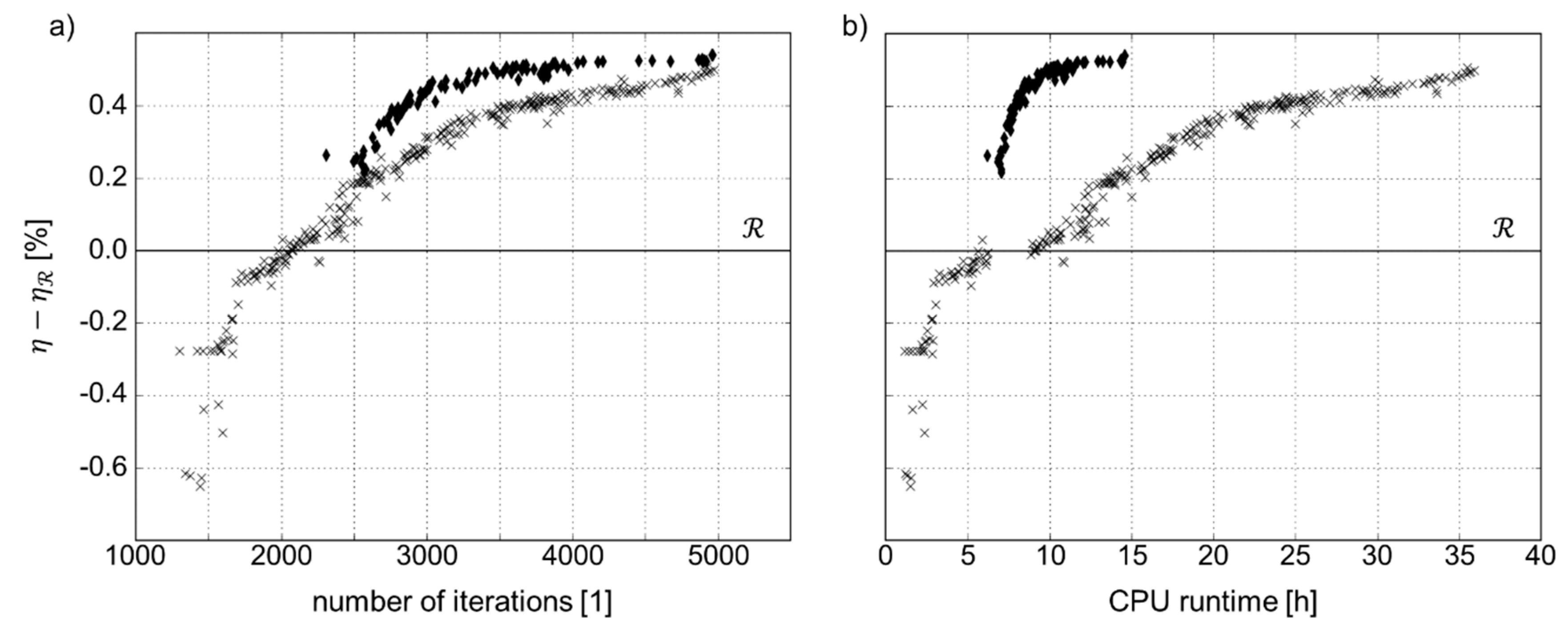
Figure 8 representatively shows the behavior of both holistic design strategies for the first 5000 iteration steps while searching for an optimal solution for problems (7) and (9). Obviously, the decoupled optimization strategy (crosses) is able to find a first valid design four to five times faster than the all-at-once approach (diamonds) due to the reasons named above. Especially, the consideration of a higher number of constraints, as well as the execution of both the compressor and the combustor analysis tool for every single iteration, lead to a less efficient convergence of the all-at-once approach at the beginning of the design process. The extended runtime in this phase, however, enables the optimizer to find a more efficient first valid design compared to the decoupled approach. With regard to the overall runtime, the all-at-once approach is up to three times faster for the same number of iteration steps because of the single combustor performance analysis for each compressor design proposal instead of executing a complete subsystem optimization. As can also be seen in
Figure 8, with the decoupled approach a higher number of valid designs is identified, see also
Table 2, although the first designs are underperforming in comparison to
, while all valid designs of the all-at-once approach are instantly more efficient than
. Nonetheless, the final best efficiency values are nearly the same for both processes.
In summary, the selection of the design strategy depends on the intentions or requirements of the user: If an optimal design has to be found within a restricted time frame, the all-at-once approach should be applied. However, if a target value must be met as quickly as possible, the decoupled strategy would be the preferred option. Nevertheless, direct consideration of all component-specific design trends in every design step of the all-at-once approach allows an early consideration of individual design requirements and the creation of a widely dispersed holistic engine population. This finally leads to slightly better results when comparing both methods in
Figure 7.
Both all-at-once and decoupled strategy may be seen as suitable here. With respect to intellectual property rights (IPR) problems in case of cooperating companies and departments, an all-at-once approach requiring full software access to all component analysis tools is not feasible. Instead, the decoupled approach should be preferred, in which sharing of local design parameters and constraints (here and ), as well as specific parametrization strategies, is not required. The combustor design process of the decoupled approach is similar to a black box, where only the interface parameters are shared and the result is fed back to the overall design process.
However, it must be kept in mind that the decoupled strategy is an optimization double-loop. Fully converged, i.e., optimal combustor designs cannot be guaranteed, because noisy combustor results are fed back to the global search. This is due to the fact that the evolutionary optimization algorithm CMA-ES is used for the individual combustor search according to Equation (8). Future studies with an increased number of design evaluations to investigate the level of uncertainties are being conducted at the moment. Nonetheless, in comparison to the isolated optimized design , better results are obtained independently of the choice of the holistic design approach.
In
Figure 7, annulus geometries for design
representing a non-dominated solution with low emissions from the all-at-once strategy, and tradeoff design
from the decoupled approach corresponding to designs with low emission and maximal efficiency, are shown and compared to the reference design
. For all three configurations (
,
,
), similar overall design requirements like overall compressor pressure ratio, shaft speed, environmental conditions, etc., have been used. As can be seen, the annulus outline for both designs
and
deviates from the reference design
. While the cross section area of design
increases, especially in the S-duct section and the first stages of the bladed part, the annulus contour of design
is located on a lower mean radius with similar cross section areas.
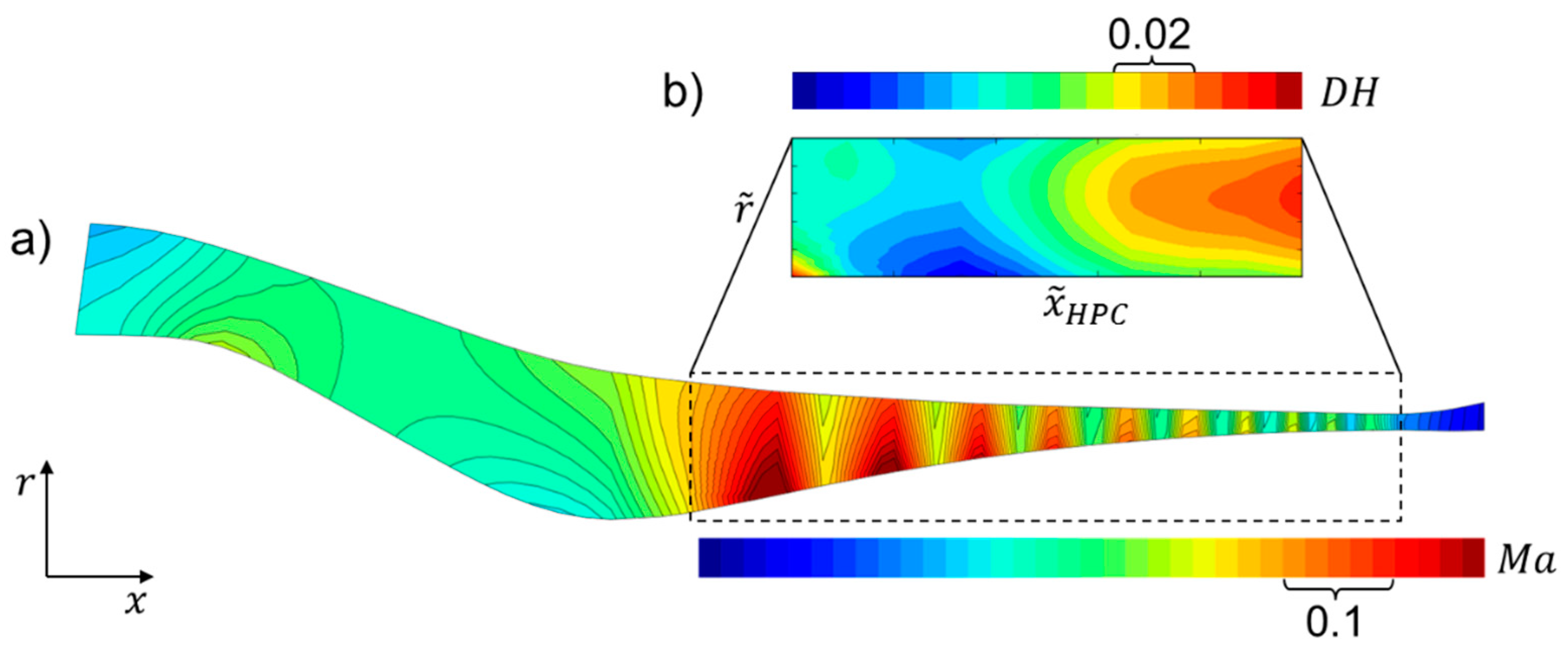
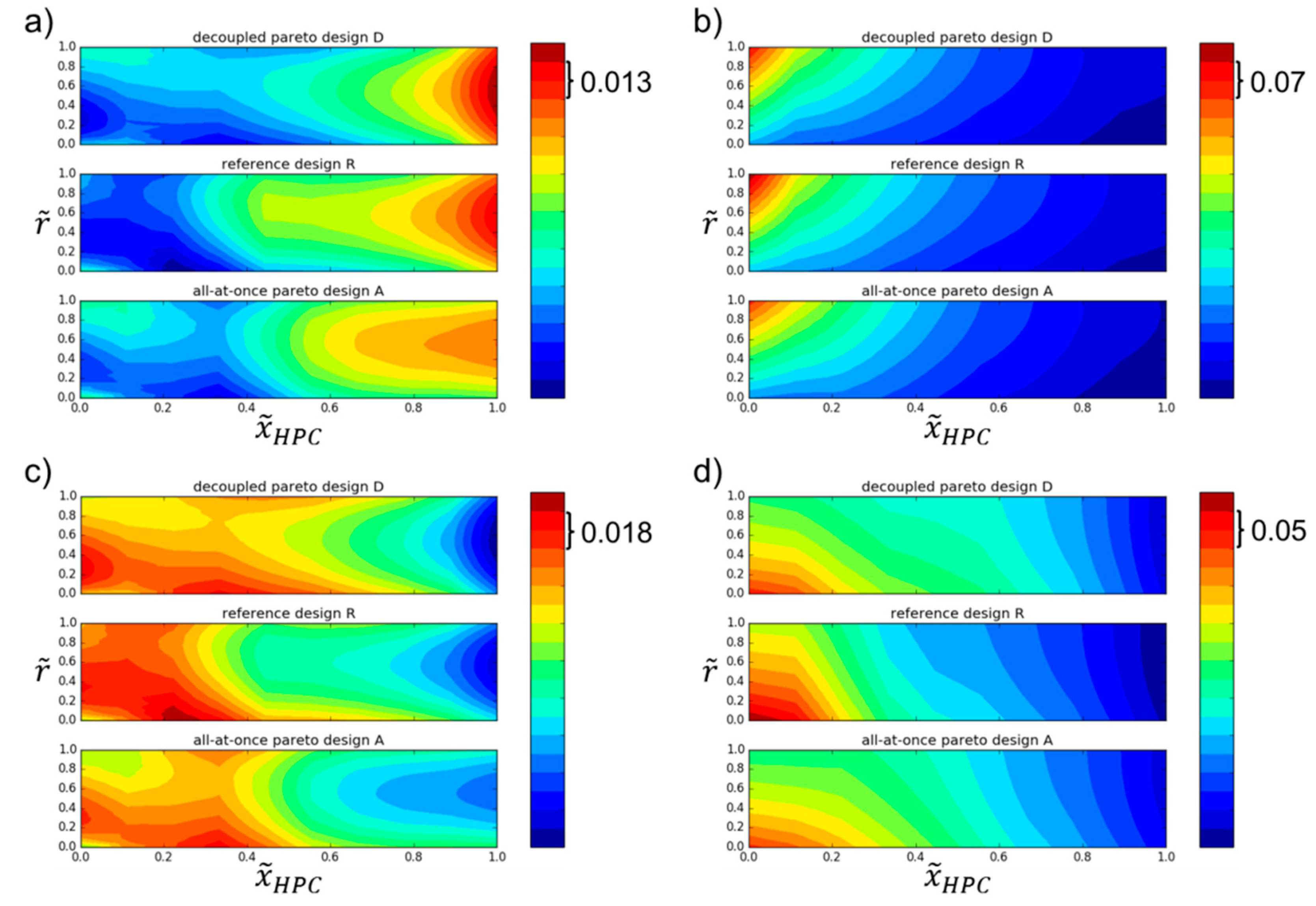
The performance benefits can be explained by the geometry adaption and the consequently changed aerodynamic flow conditions. For both compressor configurations
and
, the inflow to the bladed part was optimized.
Figure 9b,d shows a more homogeneous velocity profile in radial direction at the first rotor and stator positions. Additionally, lower relative tip Mach numbers, especially at inlet of rotor one and two, and decreased inlet Mach numbers at the front stator compared to the reference geometry are clearly recognizable. The lower velocity results in a decreased loading in the front part of the compressor, which is indicated by lower de Haller numbers and lower stage pressure ratios shown in
Figure 9a,c. This leads to lower flow loss around the blades, and thus higher efficiency. The loading decrease of design
compared to
is higher than the reduction between
and
. This can be traced back to the increased cross section area for the same mass flow rate.
Furthermore, the axial chord lengths, as well as the space-to-chord ratios, have been changed. The increased space-to-chord ratios for design and lead to a reduced number of blades, which also results in lower losses due to fewer wall interactions and, finally, to increased efficiency. However, the geometric changes result in a minor reduction of the surge margin, which is still acceptable and uncritical as the surge margin constraint is fulfilled.
Several interface values initially set to the fixed interface parameters of design have changed during the holistic optimization. Compared to the reference design, the temperature was reduced by six degrees in design and with a constant overall compressor pressure ratio. This finally leads to a higher cooling performance of the air flow in the combustion chamber supporting the cool down of the hot combustion gas and stopping the NOx production. Moreover, the materials are not loaded so heavily.
The diffusor geometry has changed towards a lower diffusor exit height, a lower exit mean radius, and a longer compressor bladed part in configuration , in which the latter leads to a shorter diffusor part. Design has a diffusor exit geometry similar to , but a shorter bladed part resulting in a longer diffusor and lower exit flow angle.
The present geometry changes have to be discussed in the context of mass distribution, as it is an important criterion for overall engine design. This step has been neglected in the present paper because of the focus on aerodynamic gas path design. The release of the interface parameters supports the design flexibility, as it is now possible to meet a range of parameters rather than having to meet specific values that are often based on experience or defined too early in the design process by limited tools.


