Steady-State and Transient Response of a Micromechanical Broadband Shoaling Amplifier †

Micro and Nanosystems, Department of Mechanical and Process Engineering, ETH Zurich, Tannenstrasse 3,8092 Zurich, Switzerland
*
Author to whom correspondence should be addressed.
†
Presented at the Eurosensors 2017 Conference, Paris, France, 3–6 September 2017.
Proceedings 2017, 1(4), 352; https://doi.org/10.3390/proceedings1040352
Published: 7 September 2017
(This article belongs to the Proceedings of Proceedings of Eurosensors 2017, Paris, France, 3–6 September 2017)
Abstract
:An in-plane MEMS broadband shoaling motion amplitude amplifier based on a coupled mass-spring system is presented. It is shown how the amplification amplitude can be traded for the operational bandwidth by design. Three devices with different numbers of masses (three, five and seven), but all of them with the same total mass, were fabricated in silicon. The achieved baseline-amplification × bandwidth product ranges from 18.0 dB × 11.5 kHz for the seven mass device to 27.7 dB × 3.9 kHz for the three mass device. Transient recordings show amplification along the mass-spring-chain. The response time to reach the baseline amplification was found to be in the order of 10−4 s. This passive device can be used for ultra-low power structural and environmental monitoring (e.g., bridges, pipelines or rock-faces).
1. Introduction
Frequency–selectivity and sensitivity are important for structural health monitoring. Previously we have shown that shoaling amplitude amplification by a coupled mass-spring chain is an effective way to achieve quasi band-pass zero power mechanical amplification of vibrations [1,2]. The approach does not rely on resonance like many acoustic emission sensors (e.g., [3]) and does not amplify low frequencies—which may contain environmental noise—in contrast to lever mechanisms [4]. Building upon the results in [1,2] which either suffer from spurious modes (out-of-plane design) or can only be read out at the last mass (in-plane design), we present an in-plane shoaling amplifier with small mirrors on top of each resonator for full optical characterization.
2. Materials and Methods
2.1. Concept and Design
The mechanical amplifier is based on a mass-spring system (Figure 1a), where the individual mass-spring pairs have the same Eigenfrequency
and the spring constants decrease by a constant factor α along the chain
Which further determines the decrease of the masses. Incoming vibrations are traveling from the largest to the smallest mass and thus shoaled, similar to a Tsunami. An exemplary transfer function of mn/m0 with n = 5 is given in Figure 1b. With the design constraints (1) and (2), an off-resonant amplification can be observed. This baseline amplification is defined as the lowest amplification between the first and the last resonance and the bandwidth is the frequency band over which this amplification is achieved. Three designs with concentrically arranged masses were realized. All designs have the same center mass dimensions and total mass, but vary in the number of coupled masses and the spring stiffness decrease factor α. Each resonator of every design was simulated with FEA to fulfill the design constraints (1) and (2) with ω0 (14 kHz) and corresponding spring constants ki (from 3 to 464 kN/m). Figure 1c shows ¼ of design N3 (three masses, α = 11.7), ½ of N5 (five masses, α = 3) and ¼ N7 (seven masses, α = 1.9)—the designs are two-fold mirror symmetric.
2.2. Simulation
The experimental results were compared to a lumped element model (Figure 4b), based on the differential equations of a uniaxial multi-degree of freedom coupled mass-spring system (e.g., [5]). The frequency response of the devices was obtained with complex matrix inversion and linearly scaled to fit the measured frequency range.
2.3. Fabrication
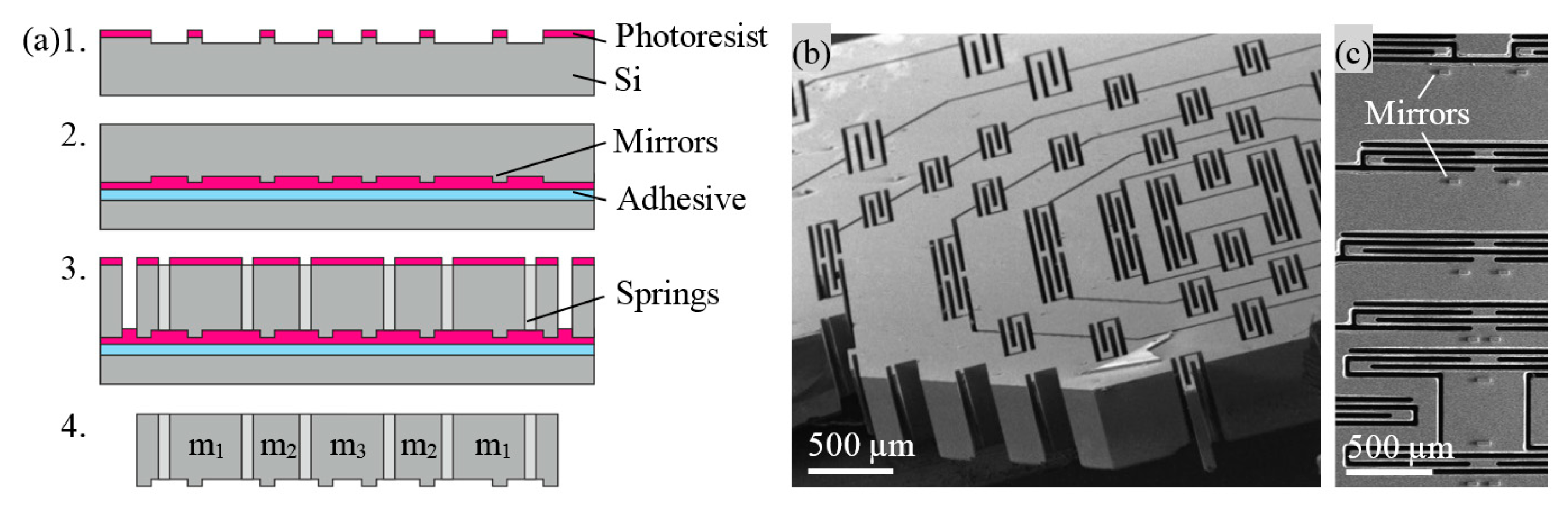
The devices were fabricated from a 500 μm double-side polished Si wafer. First, mirrors were etched on one side for optical characterization (Figure 2a), then the patterned surface was protected by photoresist and mounted on a carrier wafer with mounting adhesive. Masses, springs and dies were defined by backside through-wafer DRIE. Finally, the dies were removed from the carrier wafer in acetone and cleaned with piranha. SEM pictures of a fabricated device are given in Figure 2b,c.
2.4 Characterization
The fabricated devices were mounted vertically on a linear piezo actuator and characterized with a Polytec MSA-400 Laser Doppler Vibrometer (LDV) (Figure 3a). Each mass was measured individually, by focusing the laser of the LDV on the specific mirror (Figure 3b). To obtain the transfer functions, the devices were excited with white noise in the frequency bandwidth of the measurement range. The frequency spectrum of the mass of interest was normalized with the input (mi/m0). The transient measurements utilized the triggering function of the LDV to synchronize the excitation signal with the measured signal. All measurements were averaged 256 times.
3. Results and Discussion
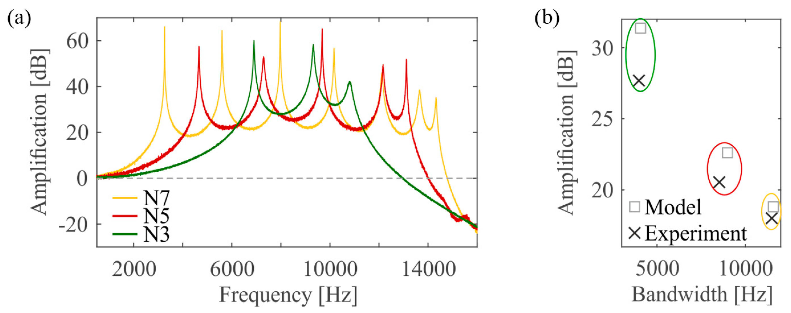
Comparing the frequency response of the three different designs shows that increasing the number of masses but with the same total mass yields lower baseline amplification and higher bandwidth (Figure 4a: N3: 27.7 dB × 3.9 kHz; N5: 20.5 dB × 8.5 kHz; N7: 18.0 dB × 11.5 kHz, product not constant). The transfer functions also show that the minimum amplifications are not at one level, as in Figure 1b, this can be attributed to a slight frequency mismatch of the individual masses. Some stiffer springs in the design were thicker by design (Figure 2b) and their stiffness was thus differently affected by the mask undercut of the ICP process. This results in a reduced baseline amplification when the experimental data is compared to the model (Figure 4b: N3: −35%; N5: −22%; N7: −9%). The bandwidth is not as much affected and matches the expectations (N3: −4%; N5: −5%; N7: −1%).
Figure 4.
(a) Transfer functions measured at center mass for all designs. The larger the factor α (spring stiffness decrease), the smaller the bandwidth and the higher the amplification; (b) Comparison with lumped model.
Figure 4.
(a) Transfer functions measured at center mass for all designs. The larger the factor α (spring stiffness decrease), the smaller the bandwidth and the higher the amplification; (b) Comparison with lumped model.

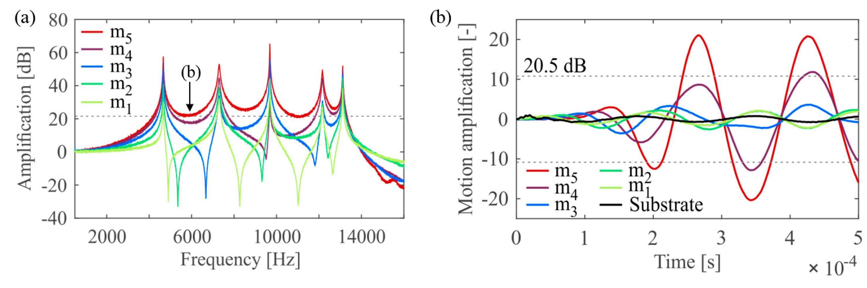
The transfer function of m1 to m5 for N5 is given in Figure 5a. While the spectrum of m5 shows resonance peaks at the five Eigenmodes and no anti-resonances, the outermost mass m1 shows four anti-resonances between the normal modes, corresponding to a 180° phase shift from mode to mode. Further, m2 shows three, m3 two and m4 one anti-resonance. This behavior is consistent with the expected Eigenmodes and with literature, where in the first mode all masses move in phase and in the last mode all masses move with 180° phase change compared to their neighbors [5]. The dynamic, off-resonant response of N5 (input 5848 kHz sine) shows the shoaling amplification towards the center mass (Figure 5b). The incoming wave travels from the outermost mass m1 towards the center mass m5 and is amplified. Baseline amplification of 20.5 dB is already reached by m5 within the first oscillation in 0.2 ms. The system is oscillating at a beat frequency, thus temporarily much higher amplitudes than baseline amplification are reached.
4. Conclusions
A mechanical amplifier based on a coupled mass-spring system and fabricated with through-wafer DRIE is presented. It is shown how bandwidth and amplification can be tuned by design. To achieve a good frequency matching, the spring thicknesses should be kept the same for all spring designs due to fabrication offsets. Further, off-resonant amplification has been experimentally verified and short response time of 0.2 ms to reach baseline amplification has been demonstrated. Future work will be targeted towards increasing the amplification by coupling more masses.
Acknowledgments
The authors gratefully acknowledge the support of the FIRST-CLA cleanroom staff of ETH Zürich (especially Donat Scheiwiller) as well as the help of the cleanroom staff at BRNC in Rüschlikon. Ankit Jain is acknowledged for assistance in device fabrication. This work has been carried out in the framework of the XSense2 project, scientifically evaluated by the Swiss National Science Foundation (SNSF) as well as financed by the Swiss Confederation and funded by Nano-Tera.ch.
Conflicts of Interest
The authors declare no conflict of interest. The founding sponsors had no role in the design of the study; in the collection, analyses, or interpretation of data; in the writing of the manuscript, and in the decision to publish the results.
References
- Muller, M.; Maiwald, V.; Kach, M.; Hierold, C.; Roman, C. A passive micromechanical broadband amplifier for acoustic emission sensing. In Proceedings of the 18th International Conference of Solid-State Sensors, Actuators Microsystems (TRANSDUCERS), Anchorage, AK, USA, 21 June 2015; pp. 1129–1132. [Google Scholar]
- Maiwald, V.; Müller, M.; Ritz, C.; Roman, C.; Hierold, C. Shoaling vibration amplifier with flattened transfer function and suppressed spurious modes. In Proceedings of the IEEE 30th International Conference on Micro Electro Mechanical Systems (MEMS), Las Vegas, NV, USA, 22 January 2017; pp. 1154–1157. [Google Scholar]
- Saboonchi, H.; Ozevin, D.; Kabir, M. MEMS sensor fusion: Acoustic emission and strain. Sens. Actuators A Phys. 2016, 247, 566–578. [Google Scholar] [CrossRef]
- Zeimpekis, I.; Sari, I.; Kraft, M. Characterization of a Mechanical Motion Amplifier Applied to a MEMS Accelerometer. J. Microelectromech. Syst. 2012, 21, 1032–1042. [Google Scholar] [CrossRef]
- Jazar, R.N. Multi Degree of Freedom Systems, Frequency Response. In Advanced Vibrations: A Modern Approach, 1st ed.; Springer: Boston, MA, USA, 2013; pp. 233–308. [Google Scholar]
Figure 1.
(a) Lumped mass-spring model. Resonators with the same Eigenfrequency are coupled in series. Spring stiffnesses and masses (exception: mn) decrease with a constant factor α; (b) Corresponding transfer function of the last mass in a system with five coupled masses with indicated baseline amplification and bandwidth; (c) Overview of the 3 different designs: ¼ N3, ½ N5 and ¼ N7. They have all the same total mass but different factors α (11.7, 3.0 and 1.9 respectively).
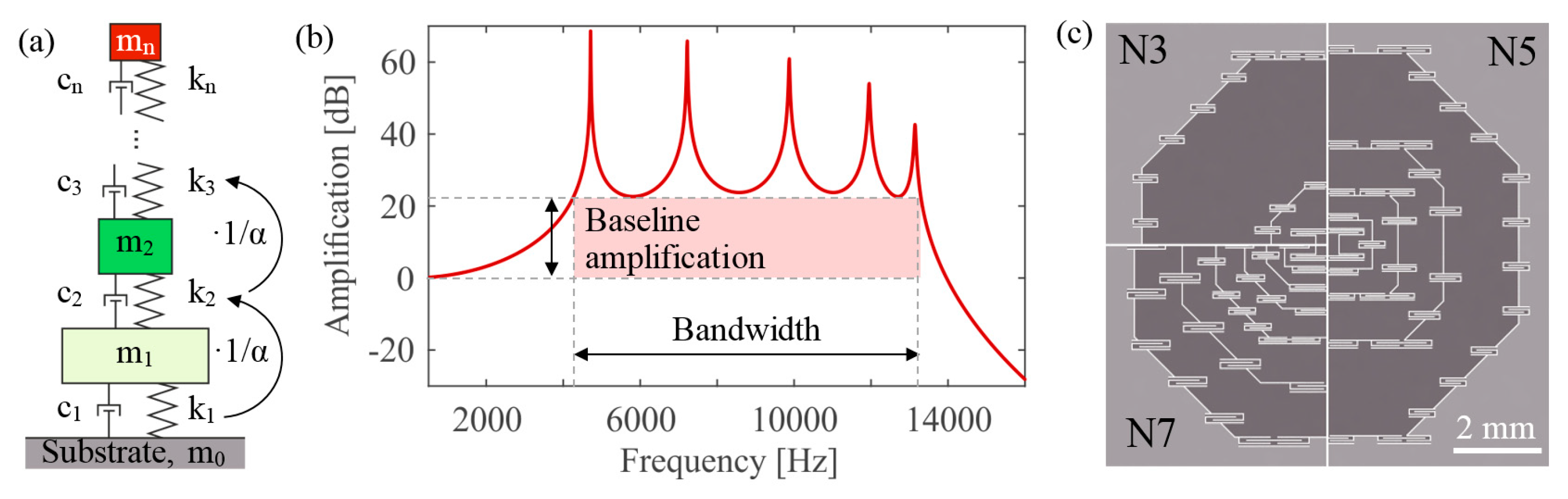
Figure 2.
(a) Fabrication process flow: 1. Patterning of photoresist and dry etching of mirrors, 2. Photoresist protection of mirrors and mounting on carrier wafer, 3. Patterning of photoresist and through-wafer DRIE of springs, masses and dies, 4. Removal of dies from carrier wafer and cleaning with piranha; (b) SEM tilted top view of N7; (c) SEM back view detail with mirrors.

Figure 3.
(a) Measurement setup; (b) Small dry-etched Si mirrors on top of all masses allow to optically track the movement (CAD drawing).
Figure 3.
(a) Measurement setup; (b) Small dry-etched Si mirrors on top of all masses allow to optically track the movement (CAD drawing).
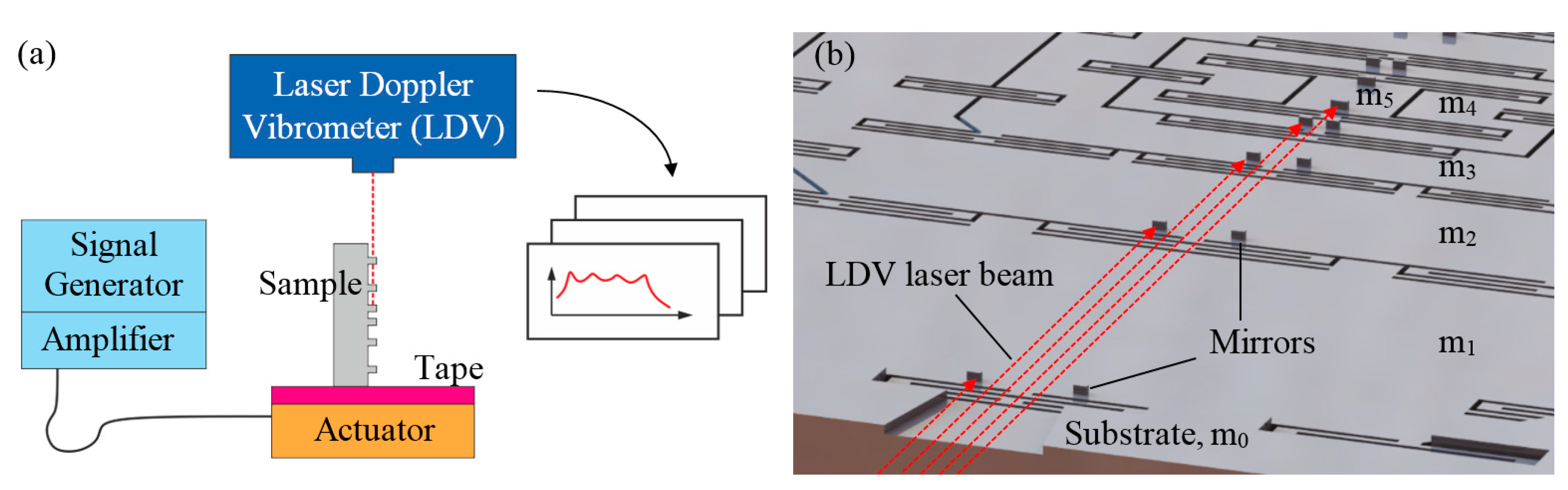
Figure 5.
(a) Transfer functions of masses of device N5. Expected anti-resonances can be observed for m1 to m4; (b) Dynamic off-resonant response of N5 at 5845 Hz, between first and second Eigenmode. Wave travels from the substrate towards the center mass m5 and is amplified. Baseline amplification is reached approx. within 0.2 m5.

Publisher’s Note: MDPI stays neutral with regard to jurisdictional claims in published maps and institutional affiliations. |
© 2017 by the authors. Licensee MDPI, Basel, Switzerland. This article is an open access article distributed under the terms and conditions of the Creative Commons Attribution (CC BY) license (https://creativecommons.org/licenses/by/4.0/).
Share and Cite
MDPI and ACS Style
Müller, M.; Maiwald, V.; Roman, C.; Hierold, C. Steady-State and Transient Response of a Micromechanical Broadband Shoaling Amplifier. Proceedings 2017, 1, 352. https://doi.org/10.3390/proceedings1040352
AMA Style
Müller M, Maiwald V, Roman C, Hierold C. Steady-State and Transient Response of a Micromechanical Broadband Shoaling Amplifier. Proceedings. 2017; 1(4):352. https://doi.org/10.3390/proceedings1040352
Chicago/Turabian StyleMüller, Michelle, Verena Maiwald, Cosmin Roman, and Christofer Hierold. 2017. "Steady-State and Transient Response of a Micromechanical Broadband Shoaling Amplifier" Proceedings 1, no. 4: 352. https://doi.org/10.3390/proceedings1040352