Micromachined Tube Type Thermal Flow Sensor for Adult-Sized Tracheal Intubation Tube †
by
Shun Watanabe
1,*, 
Yoshihiro Hasegawa
1,
Miyoko Matsushima
2,
Tsutomu Kawabe
2 and
Mitsuhiro Shikida
1 1
Hiroshima City University, 3-4-1, Ozuka-Higashi, Asa-Minami-Ku, Hiroshima 731-3194, Japan
2
Nagoya University, 1-1-20, Daiko-Minami, Higashi-ku, Nagoya 461-8673, Japan
*
Author to whom correspondence should be addressed.
†
Presented at the Eurosensors 2017 Conference, Paris, France, 3–6 September 2017.
Proceedings 2017, 1(4), 357; https://doi.org/10.3390/proceedings1040357
Published: 7 September 2017
(This article belongs to the Proceedings of Proceedings of Eurosensors 2017, Paris, France, 3–6 September 2017)
Abstract
:We designed and fabricated a tube-type thermal flow sensor for fabricating an adult-sized tracheal intubation tube device intended for clinical practice. The sensor film was packaged into the inside surface of the tube by interface tension and parylene coating, and a flow sensor for an adult-sized tracheal intubation tube was successfully produced. We experimentally investigated flow rate detection and response time and found that the flow sensor fitted King’s model in terms of flow rate detection and has a sufficiently short response time of 59 ms. Thus, we concluded that the developed sensor will be applicable to measuring breathing characteristics of adults in the near future. Finally, the developed sensor was assembled into a tracheal intubation tube actually used in medical treatment.
1. Introduction
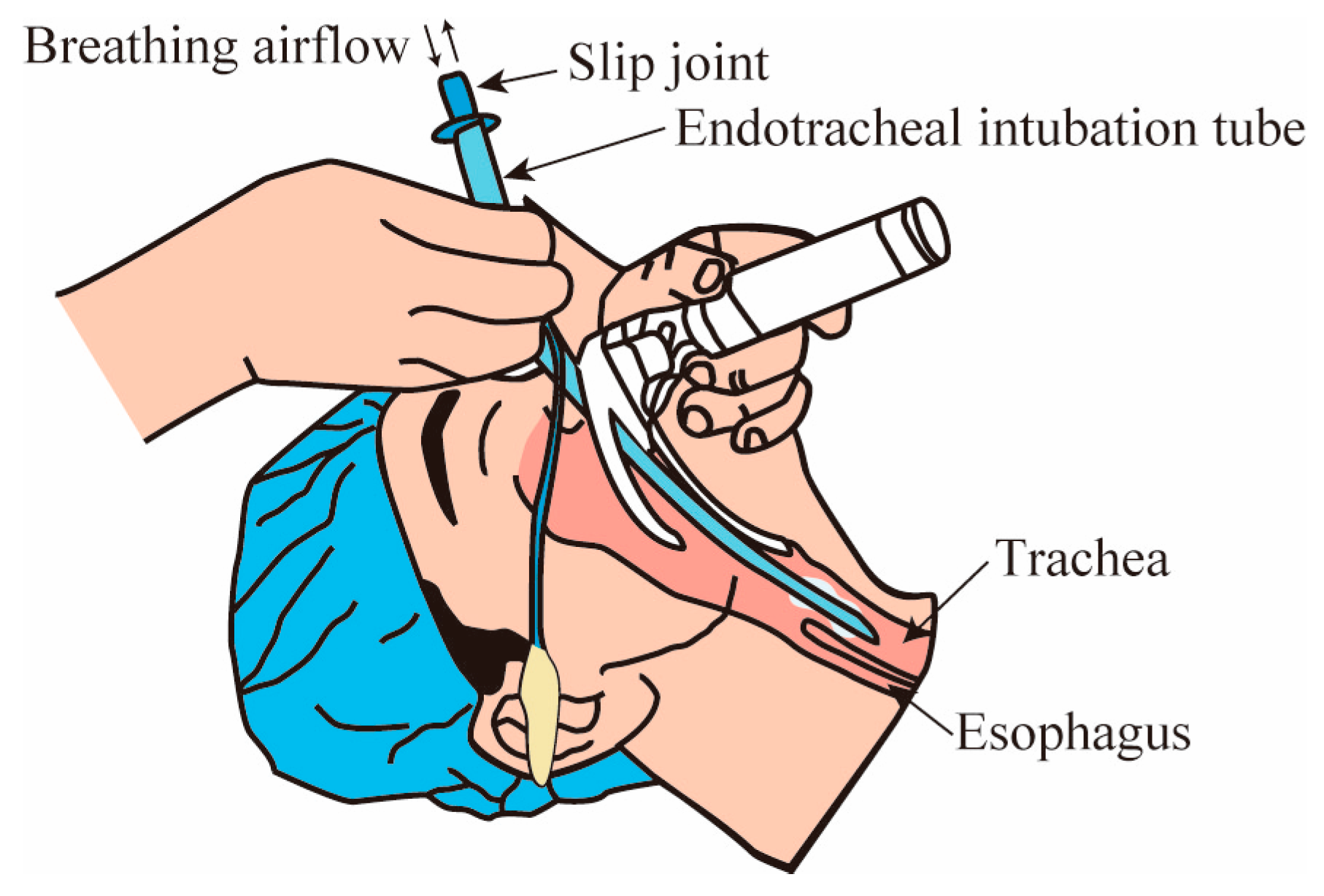
Tracheal intubation is carried out to secure cardiopulmonary resuscitation or artificial breathing management of patients under general anesthesia (Figure 1, [1]). A flexible plastic tube is carefully intubated into the airway. This is because intubating the tube is into the esophagus instead of the airway can lead to serious medical accidents. Once the tube is intubated into the airway, it is tightly fixed to the inside surface by swelling a balloon located at the near end of the tube. The balloon structure generally disturbs the ciliary motion working as a foreign-body remover at the airway surface. Thus, the inserted tube is preferably extubated immediately when the spontaneous breathing of the patient has returned to normal after treatment. However, the optimal extubation timing is difficult to judge. This is because the tube separates from the artificial ventilator during extubation and does not have an airflow measurement function. Thus, the tube is unfortunately re-intubated into the airway again if it is extubated too early. This treatment is thought to increase the length of hospital stays.
To overcome this problem, a microelectromechanical systems (MEMS) flow sensor was assembled into an intubation tube [2,3]. The intubation tube device with the MEMS flow sensor can detect the airflow passing through the tube in real-time. Thus, it can easily judge whether the tube is inserted into an airway or esophagus during intubation and measure the spontaneous breathing properties quantitatively just before extubation. In previous work, we mounted the developed tube-type thermal flow sensor on an infant-sized tracheal intubation tube and verified the proof-of-concept of the proposed device on small laboratory animals.
In this study, we designed and fabricated a tube-type thermal flow sensor for fabricating an adult-sized tracheal intubation tube device intended for clinical practice.
2. Tube-Type Thermal Flow Sensor
The adult-sized tracheal intubation tube consists of an intubation tube, a balloon, and a slip joint. The artificial ventilator is connected to the slip joint element. Figure 2 shows the designed tube-type flow sensor for an adult-sized tracheal intubation tube. The tube flow sensor was designed to have an 11 mm outside diameter to fix it to the inside surface of a slip joint. A double wrapped tube structure was applied to form a cavity on the backside of the heater for the thermal isolation. The difference in thickness of the two tubes was thinned to 1.0 mm to decrease the flow resistance at the tube structures. Two heaters working as the flow-velocity and flow-direction sensors were formed on the film, and it was mounted onto the inside surface of the inner tube.
Figure 3 shows the fabrication process of the tube-type thermal flow sensor. Two heaters working as the sensors were formed on the 12.5-μm-thick polyimide film. To assemble the large thin sensor film onto the inside surface of the tube, the film was first plastically deformed by using interface tension (Figure 3a). Then, the bent sensor film was inserted and fixed onto the inside surface of the inner tube by using silicone oil (Figure 3b). The enameled wires were bonded for conducting the electrical signals by using an anisotropic conductive film, and the whole sensor’s surface was coated by a biocompatible parylene film (Figure 3c). The parylene film prevented the electric wiring area from touching the body fluid directly. Finally, the inner tube was covered by the outer one to seal the cavity completely. The produced thermal flow sensor is shown in Figure 3d.
3. Characteristics
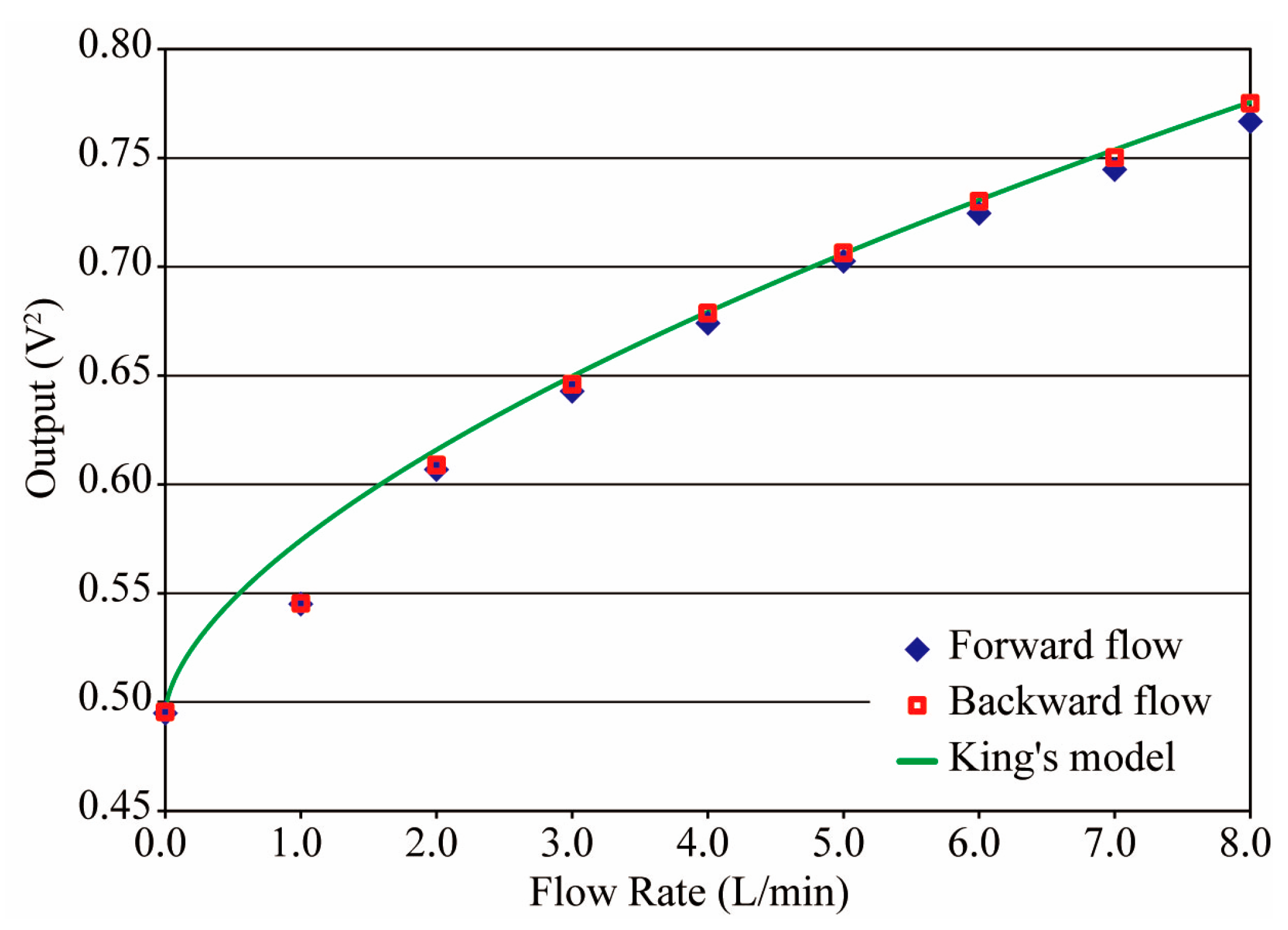
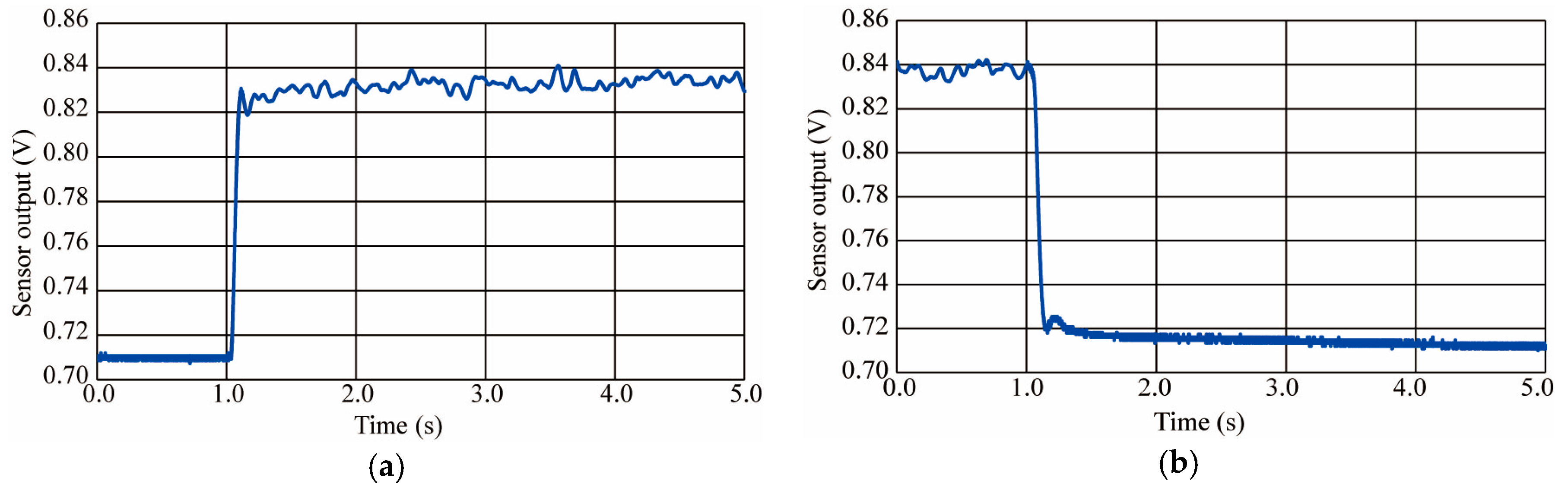
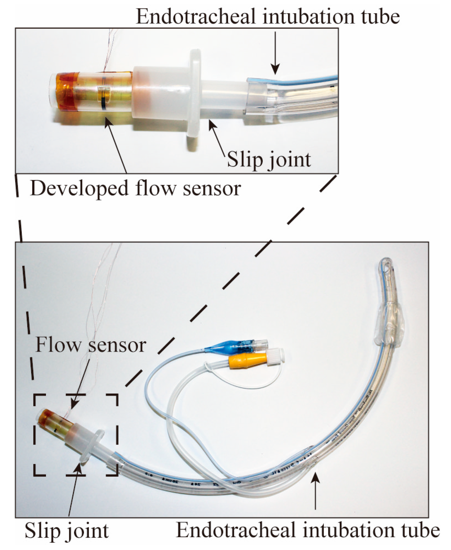
We evaluated the basic characteristic of the produced thermal flow senor. The flow rate detection property was evaluated under a range up to 8.0 L/min in both flow direction conditions because breathing is oscillating airflow. The obtained sensor output values in both flow directions were coincident and fitted King’s model based on the thermal convection principle, as shown in Figure 4. The response time of the produced thermal flow senor was found to be 59 ms (Figure 5). The typical breathing cycle of an adult is 3.3 s, so we concluded that the developed sensor responds fast enough to measure the breathing airflow. Finally, the produced flow sensor was assembled into a tracheal intubation tube actually used in medical treatment (Figure 6).
4. Conclusions
A tube-type thermal flow sensor was produced to be assembled onto the inside surface of a slip joint in a tracheal intubation tube. The sensor output fitted King’s model in the flow rate measurement, and the flow sensor had a sufficiently short response time of 59 ms. Thus, we concluded that the developed sensor will be applicable to measuring breathing characteristics of adults in the near future.
Acknowledgments
This research was supported by JSPS KAKENHI Grant Number 26286034, Japan.
Conflicts of Interest
The authors declare no conflict of interest.
References
- YAO TOKUSYUKAI General Hospital ICU Manual, version 2009.
- Matsuyama, T.; Yoshikawa, K.; Yamazaki, Y.; Shikida, M.; Matsushima, M.; Kawabe, T. Integration of catheter flow sensor onto tracheal intubation tube sys-tem. In Proceedings of the Tech. Digest. MEMS Conference, Taipei, Taiwan, 20–24 January 2013; pp. 567–570. [Google Scholar]
- Shikida, M.; Yoshikawa, K.; Matsuyama, T.; Yamazaki, Y.; Matsushima, M.; Kawabe, T. Catheter flow sensor with temperature compensation for tracheal intubation tube system. Sens. Actuators A 2014, 215, 155–160. [Google Scholar] [CrossRef]
Figure 1.
Endotracheal intubation tube inserted in airway [1].
Figure 1.
Endotracheal intubation tube inserted in airway [1].

Figure 2.
Adult-sized tracheal intubation tube device: (a) Actually used adult-sized tracheal intubation tube; (b) Flow sensor integration to adult-sized tracheal tube; (c) Tube-type thermal flow sensor for adult-sized tracheal intubation tube device.
Figure 2.
Adult-sized tracheal intubation tube device: (a) Actually used adult-sized tracheal intubation tube; (b) Flow sensor integration to adult-sized tracheal tube; (c) Tube-type thermal flow sensor for adult-sized tracheal intubation tube device.

Figure 3.
Assembly of sensor film into tube: (a) Plastically bent sensor film; (b) Applying silicone oil into gap between film and tube; (c) Wiring connection and parylene C deposition; (d) Inserting sensor into outside tube.
Figure 3.
Assembly of sensor film into tube: (a) Plastically bent sensor film; (b) Applying silicone oil into gap between film and tube; (c) Wiring connection and parylene C deposition; (d) Inserting sensor into outside tube.

Figure 4.
Relationship between flow rate and sensor output.

Figure 5.
Responsive wave: (a) Rise time; (b) Fall time.

Figure 6.
Flow sensor integration to adult-sized tracheal intubation tube.

Publisher’s Note: MDPI stays neutral with regard to jurisdictional claims in published maps and institutional affiliations. |
© 2017 by the authors. Licensee MDPI, Basel, Switzerland. This article is an open access article distributed under the terms and conditions of the Creative Commons Attribution (CC BY) license (https://creativecommons.org/licenses/by/4.0/).
Share and Cite
MDPI and ACS Style
Watanabe, S.; Hasegawa, Y.; Matsushima, M.; Kawabe, T.; Shikida, M. Micromachined Tube Type Thermal Flow Sensor for Adult-Sized Tracheal Intubation Tube. Proceedings 2017, 1, 357. https://doi.org/10.3390/proceedings1040357
AMA Style
Watanabe S, Hasegawa Y, Matsushima M, Kawabe T, Shikida M. Micromachined Tube Type Thermal Flow Sensor for Adult-Sized Tracheal Intubation Tube. Proceedings. 2017; 1(4):357. https://doi.org/10.3390/proceedings1040357
Chicago/Turabian StyleWatanabe, Shun, Yoshihiro Hasegawa, Miyoko Matsushima, Tsutomu Kawabe, and Mitsuhiro Shikida. 2017. "Micromachined Tube Type Thermal Flow Sensor for Adult-Sized Tracheal Intubation Tube" Proceedings 1, no. 4: 357. https://doi.org/10.3390/proceedings1040357