A Laboratory Investigation of a Domestic Hydropower Model †


1
Department of Civil Engineering, University of Salerno, 84084 Fisciano, Italy
2
Department of Civil and Mechanical Engineering, University of Cassino, 03040 Cassino, Italy
*
Author to whom correspondence should be addressed.
†
Presented at the 3rd EWaS International Conference on “Insights on the Water-Energy-Food Nexus”, Lefkada Island, Greece, 27–30 June 2018.
Proceedings 2018, 2(11), 686; https://doi.org/10.3390/proceedings2110686
Published: 3 August 2018
(This article belongs to the Proceedings of EWaS3 2018)
Abstract
:This work shows the results of an experimental investigation on a domestic hydropower model assembled at the Laboratory of Environmental and Maritime Hydraulics of the Department of Civil Engineering, University of Salerno, Italy. Hydropower offers the opportunity to create a clean renewable source of energy, reducing carbon footprint and having a minimal impact on the environment. Small-scale hydropower plants in the domestic context are suitable for buildings with heights and roof surfaces that, in conjunction with a proper storage system, may yield capacities of up 100 kW. The device here adopted, mimicking the vertical part of a drain serving a flat complex, is composed of a storage tank of 60 l connected to a pressurized system fitted in the final downstream section with a nozzle. The available kinetic energy is converted in electricity thanks to a microturbine which drives a generator. The system is analyzed by: using different nozzles obtained by a 3D printer, varying the flowrate and attack angle at the microturbine and changing the number of blades.
1. Introduction
Renewable energy sources (RES) are based on primary sources deriving in particular from sun, water, wind and geothermal heat. These energies are inexhaustible and also called renewable energies, because they regenerate after each cycle. Several forms of renewable energy are used nowadays for the electricity production, all of them have in common that they do not produce carbon dioxide (CO2). Among them, hydropower generation is the most widespread option worldwide, being highly flexible. In 2016 hydropower generated 15.5% of the world’s total electricity and 70% of all renewable electricity [1]. Compared to fossil fuels generating an equivalent amount of electricity, hydropower displaced 3 × 10⁹ t of CO2 emissions in 2011. Nevertheless, contradictory research studies seem not to prove such tendency [2]. Another positive aspect is that the cost of hydroelectricity is relatively low. Recent deals in Denmark, Egypt, India, Mexico, Peru and the United Arab Emirates saw renewable electricity being delivered at just USD 0.05 per kWh or less.
Actually, the tendency is toward the creation of small (SHPs) or micro (MHPs) or pico-hydropower (PHPs) plants [3,4,5] due the availability of water flowing, providing power to isolated homes or to small communities. The study conducted at the Laboratory of Environmental and Maritime Hydraulics (LIDAM) of the Department of Civil Engineering (DICIV), University of Salerno, Italy, is focused on testing a system for the energy recovery from rainwater through a device able to collect water and use it for a domestic hydroelectric plant.
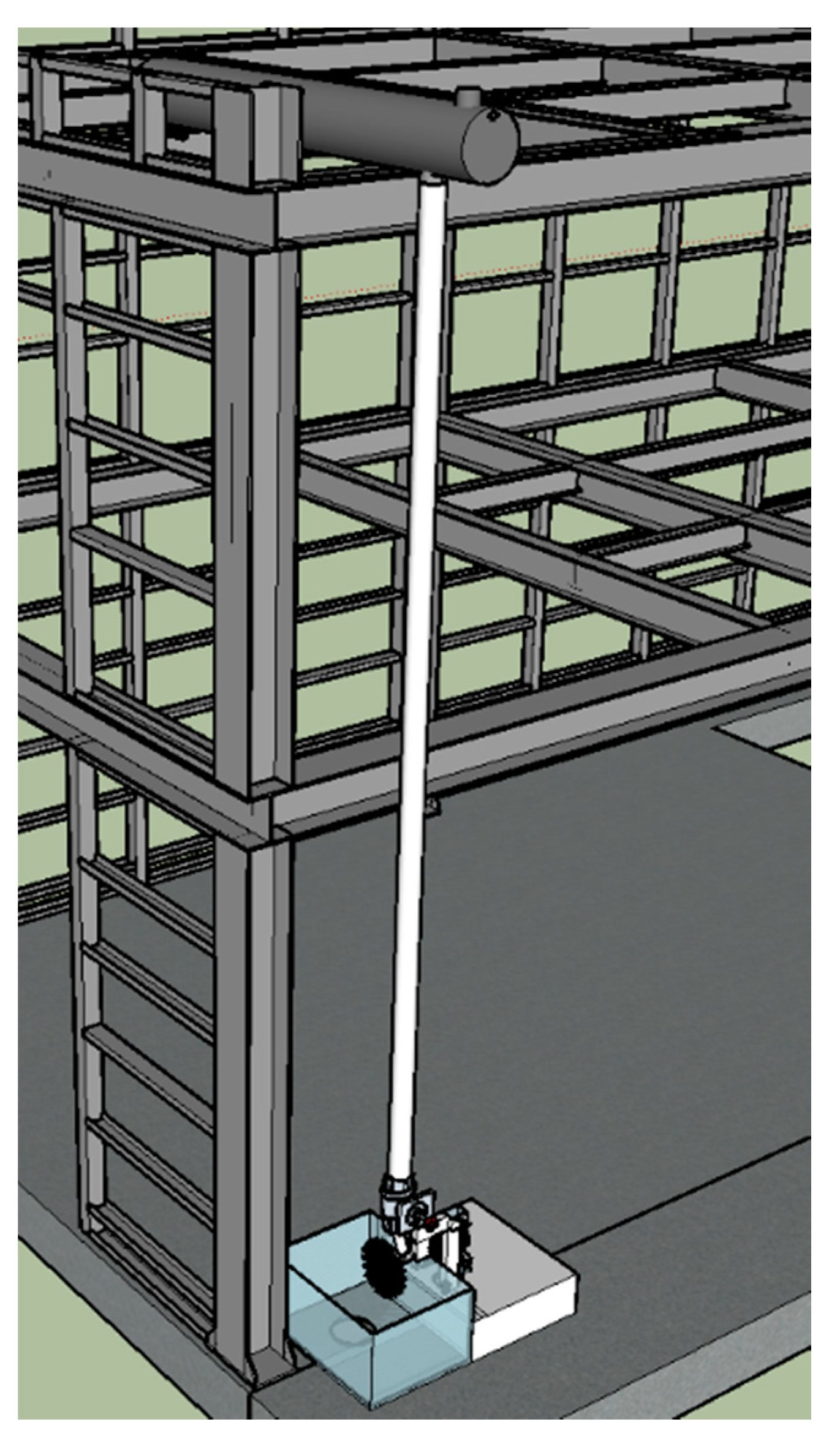
The reference system (Figure 1) consists of a tank, placed at a proper level corresponding to the building height, feeding a drain pipe. A Pelton micro-turbine connected to a 12 V generator is placed at its lower end where a nozzle yields a water jet. The hydroelectric energy produced is stored in a 12 V battery.
A commercial micro-hydroelectric kit was first tested, for which the flow rate of the water jet through the nozzle was assessed through the Bernoulli equation. This value of discharge was then reproduced in the laboratory system. The tests focused on the design of the final part of the outflow pipe. An ad-hoc structure was designed for measuring the values of the flow rates of the commercial micro-hydroelectric kit and of the second system built with the help of a three dimensional (3D) printer. In particular, a Pelton turbine and a nozzle were designed and produced with the 3D printer.
2. Methods and Materials for the Construction
A tool for measurements was built in the laboratory for the easy reading of the experimental data. The ad-hoc structure consists of a wooden part and a metal one, for housing the turbine-dynamo system, with an adjacent tank for draining the water through a grating.
2.1. Geometric Characteristics
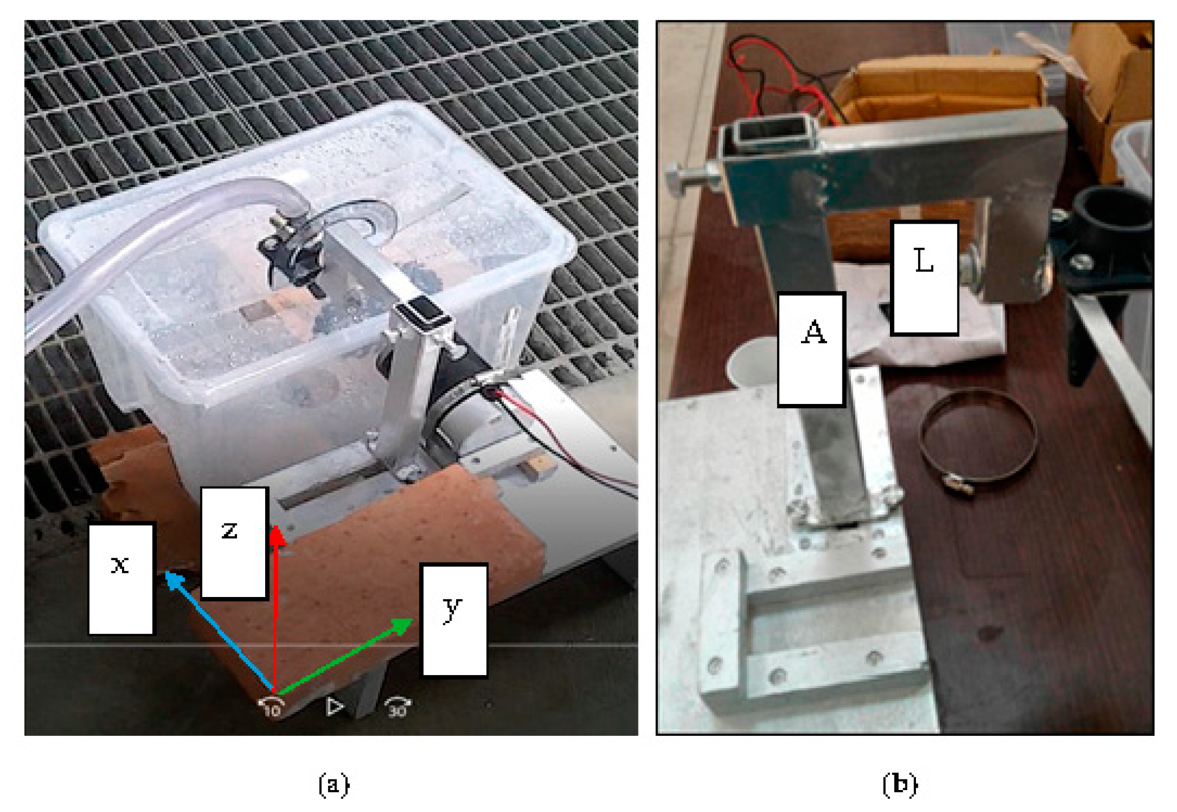
A 3D reference system was selected with origins in the left edge of it, see Figure 2a. The choice of rectangular section profiles had the purpose to avoid torsion of the structure during the tests due its high flexural strength. The metal recess was designed of 10 mm and allows the structure to move in the y direction for a maximum distance of 130 mm. The trolley, welded to the 30 × 20 section and in the shape of the IPE section bars, consists of close welded bolts which have the task of tightening the structure to the plate.
The steel section bar A (Figure 2b) of 30 × 20 × 260 cm size was connected to the T plate by welding and it is used as a translation pin z of the section bar 30 × 40 × 30 cm, which in turn is welded to the remaining L-shaped section bar. The lower part of the L-shaped section bar consists of a hole where there is a cylinder welded to a plate, allowing the nozzle to be positioned at a variable angle.
The structure can, therefore, move along y and z and the nozzle can rotate of 360° and placed to a maximum of 30 mm from the turbine. A flow and a pressure meters were placed on the supply pipe and a goniometer at the nozzle to easily identify the angle of attack.
2.2. Adopted Materials
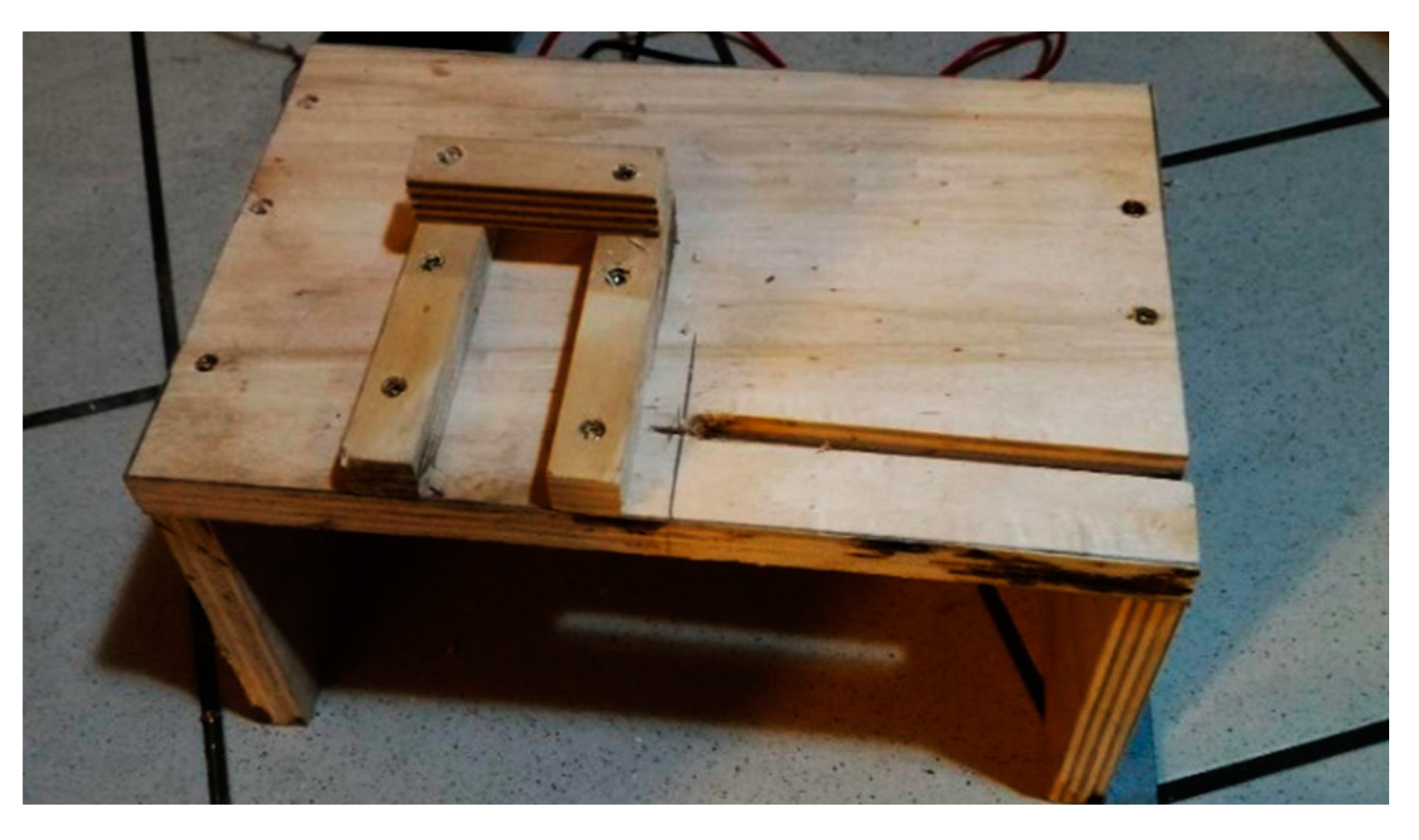
The wooden structure (Figure 3) is made of:
- three laths fixed by 3-mm screws;
- the supporting formwork in multilayer wood of size 200 × 330 × 140 mm.
The metal structure, instead, is made of:
- three steel bars with section 30 × 20 mm, of length, respectively, of 260, 80 and 60 mm;
- one steel bar with section 40 × 30 mm;
- a 2-mm perforated plate, 60 × 60 mm in size;
- a circular plate with a diameter of 30 mm;
- a 30 × 20 mm plate;
- a cart plate to make the structure move with small movements;
- bolts and screws of 4 and 8 mm to maintain the structure in one of the two allowed positions as desired.
The housing of the dynamo and the wooden structure were designed to adhere perfectly to the tank. To better position the generator, wooden slats have been inserted so as to lift the structure from the ground and form a housing for the dynamo that, through the band, keeps the whole joined together with the structure.
2.3. Expected Developing Power
A simple procedure is here applied to derive the order of magnitude of the mechanical power which can be obtained for the particular case of the pressure head HA = 4.63 m currently available at the apparatus.
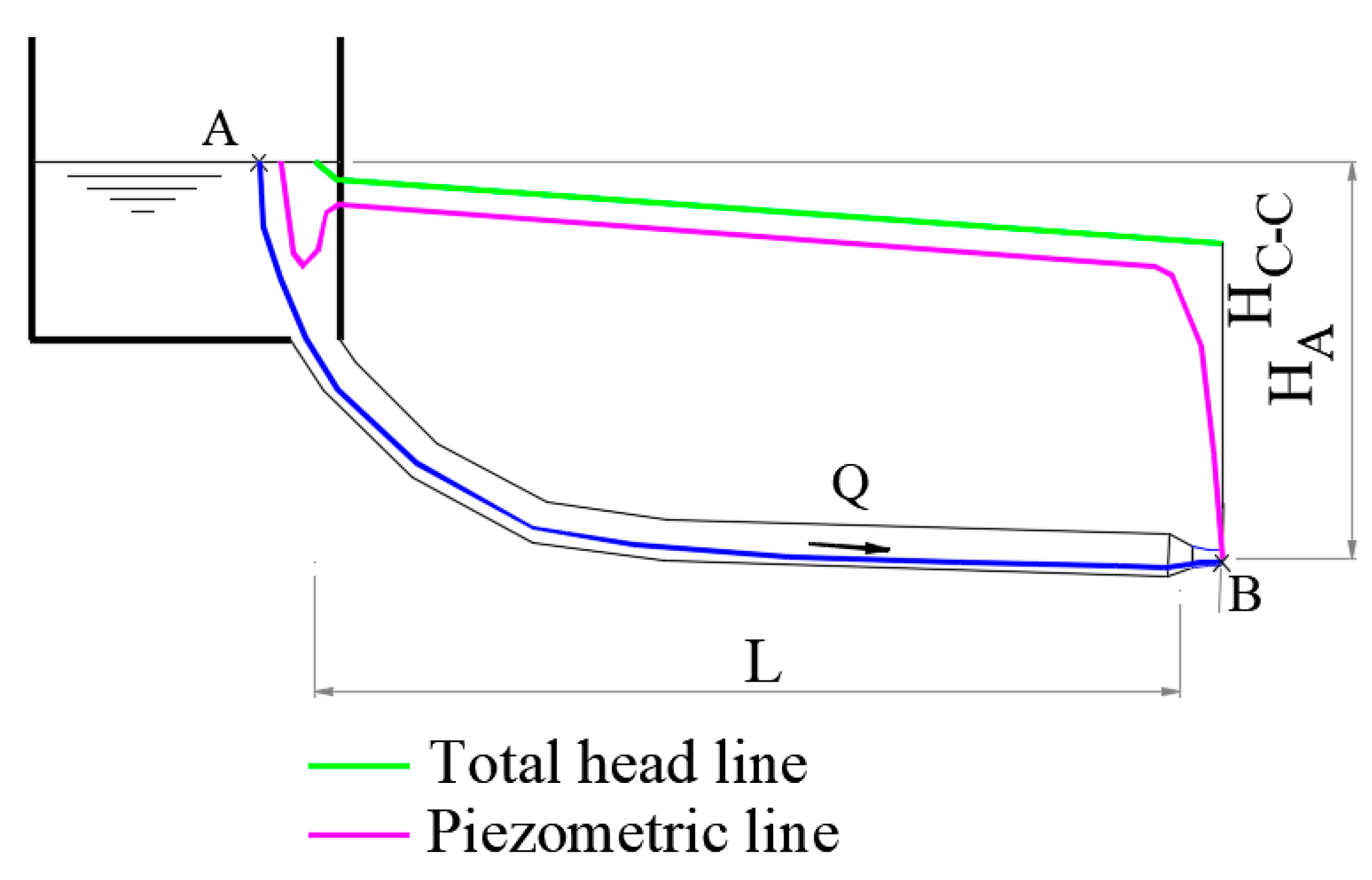
Given the gravity acceleration g = 9.81 m/s2, the cinematic viscosity υ = 1.006 × 10⁻⁶ m2/s, the pipe diameter D = 90 mm being the adopted value for the drainpipe, the diameter of the nozzle Dn = 9 mm yielding the contracted area AC-C computed with the measured contraction coefficient cc = 0.75, the Bernoulli’s theorem to the trajectory between a point A in the tank and a point B in the contracted section was used (Figure 4):
The aim was to calculate first the discharge Q of released in the atmosphere from the nozzle and then the mechanical power Pt of the fluid jet at the contracted section. The discharge was then calculated, including the local head loss at the entrance for a short pipe, with the following formula:
The formula of Darcy-Weisback was applied in it for the calculation of the head losses and the only kinetic term was considered for the contracted section. An iterative procedure was applied to calculate the discharge Q, known the areas of the final section of the nozzle (0.0001 m2) and of the pipe (0.0064 m2), the roughness of the pipe (0.2 mm), then the correspondent relative pipe roughness (ε/D = 0.0022, on the basis of the material type and of the conservation status of the internal wall). The resistance index λ was computed iteratively using the Colebrook-White Formula (3) then the discharge Q was calculated. The control for the convergence of the procedure was made calculating the energy slope J and then the corresponding hydraulic head of the tank, which is known and equal to 4.63 m from the zero reference.
The theoretical power of the jet at the contracted section is of the order Ptheor = 20 W, obtained by:
Ptheor = 9.81 Q HC-C
2.4. Realization of the Pelton 3D Turbine
The Pelton turbine chosen for the experimental campaign in the LIDAM laboratory has been designed following the measurements of the hydroelectric kit supplied Orengine International, Italy.
The variation with respect to the turbine printed in 3D lies in the geometric shape and in the number of blades, which was chosen lower in order to increase the interaxis between the components that resulted too close to each other.
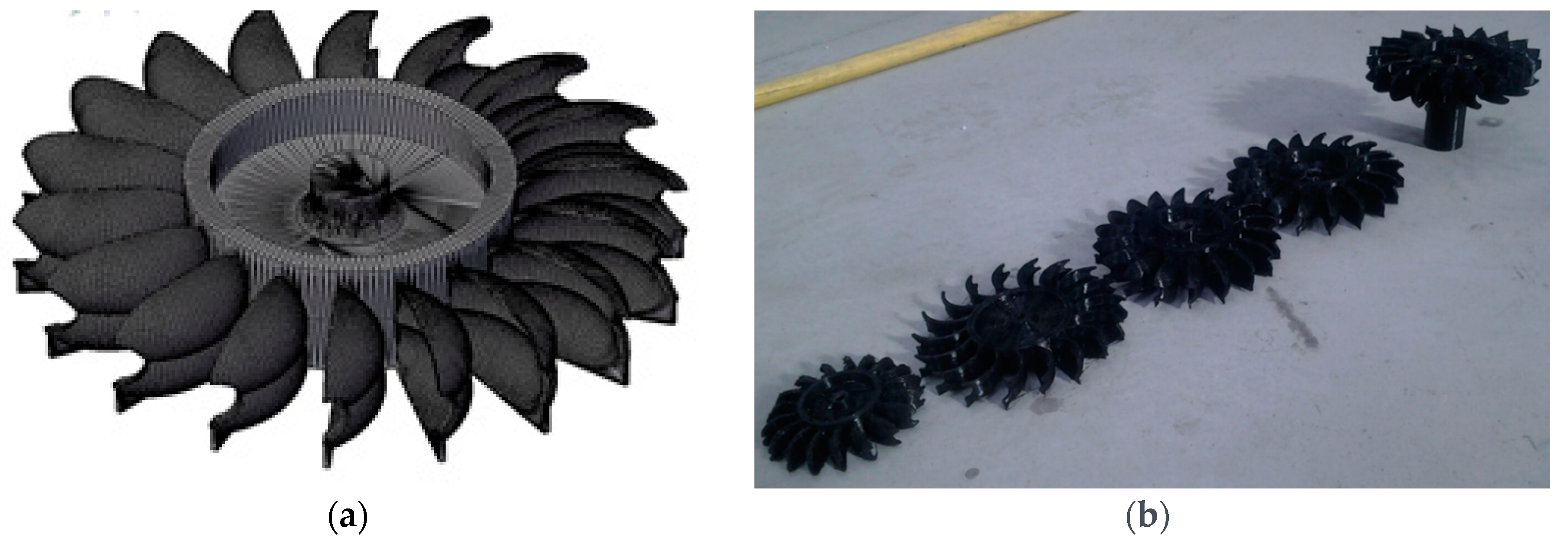
The Pelton in polylactic acid (PLA) has the following characteristics:
- 18 blades, each 22.30 mm long and thickness of 2 mm, gull-wing shape with a pair of central filaments to distribute the fluid in its basin;
- external diameter of 128 mm and internal diameter of 10 mm for coupling the dynamo motor shaft.
The turbine was designed with the help of a CAD software (Figure 5a).
By improving the setting of the reference system and leveling the plate, it was possible to increase the print quality and precision. Finally, a 3D support was created to hook it to the dynamo drive axis given in the laboratory (Figure 5b). The printing hours for the turbine were 5.30 and for the support 1.56.
3. Laboratory Results on Experiments Performed at LIDAM
The investigations carried out in the laboratory permitted to highlight the main differences between the PLA 3D-printed elements and the PVC commercial ones. In particular, the following parameters in the study of a hydroelectric plant have been considered:
- angle of attack “α”;
- turbine nozzle distance “d”;
- number of the blades.
Measurements were made with attack angles “α” of 3°, 10°, 20°, 30°, 40°, with reference to the vertical direction. The distances nozzle—point close to the turbine “d” goes from 30 mm up to 5 mm. The number of blades varies from 22 to 18.
Experimental Results
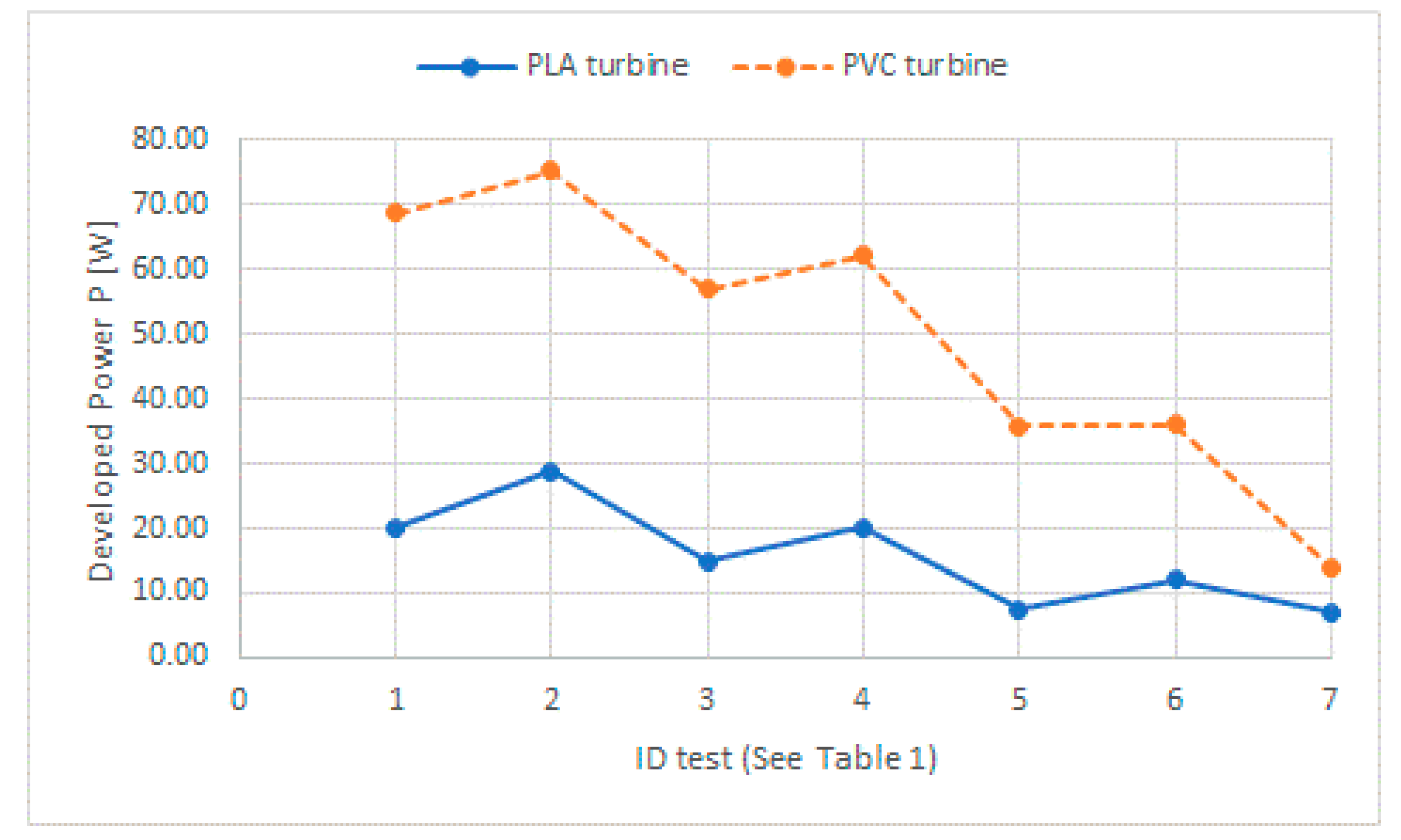
Results of the laboratory tests are represented in the following graph (Figure 6). It is shown how the power increases as “α” and “d” decreases. Then the ratio ψ between the power delivered from the commercial PPVC and the built PPLA turbines was evaluated. Test ID is related to the operating parameters as specified in Table 1.
The considered configuration of the system according to the following: a flow rate of 0.5 l/s, measured through a flow meter, a pressure of 3.20 bar, measured through a digital manometer, keeping the angle of attack of 3° constant and with an average distance from the nozzle to the point closer to the turbine of 10 mm, yielded the optimal performance of the system. In particular, there will be an average power output of 75.20 W for the commercial turbine and of 28.83 W for the 3D printer built turbine.
4. Conclusions and Further Activities
The studies conducted on the built model suggest that the use of the water renewable resource can be combined in such situations in which the pluviometric occurrence is adequate. The use of the highlighted approach, in countries where the cumulate rainfall is high, can be an important source of energy and generate electricity to cover primary sources.
This application could be the future object of a further experimental study, through the use of 3D prototypes, to improve the performance of the turbine. The structure can be upgraded with elements of depression to increase the delivered power and use roofs as reservoirs for water conveying. The difference of about one third in the obtained energy power is due not only to the number of blades reduced from 22 for the commercially available turbine to 18 in the built turbine, but also in relation to the weight from 215 g to 104 g (for the PLA turbine), the material and some geometric details that have been calibrated for the available generator, which is part of the kit available on the market.
The investigations carried out on this theme and the created instruments will be the basis of an investigation campaign that will lead to actual results and possible applications in the civil engineering field of a structure with energy recovery from rainwater.
Author Contributions
The tasks of conceiving the experimental apparatus, analyzing data, drawing conclusions and writing the paper were uniformly shared among the authors.
Acknowledgments
The authors express their gratitude to Giovanni Aliberti, Department of Industrial Engineering, UNISA, for his support during the printing process of the PLA turbines.
Conflicts of Interest
The authors declare no conflict of interest.
References
- Renewables 2017 Global Status Report. Available online: http://www.ren21.net/wp-content/uploads/2017/06/17-8399_GSR_2017_Full_Report_0621_Opt.pdf (accessed on 5 December 2017).
- Deemer, B.R.; Harrison, J.A.; Li, S.; Beaulieu, J.J.; Del Sontro, T.; Barros, N.; Bezerra-Neto, J.F.; Powers, S.M.; dos Santos, M.A.; Vonk, J.A. Greenhouse Gas Emissions from Reservoir Water Surfaces: A New Global Synthesis. BioScience 2016, 66, 949–964. [Google Scholar] [CrossRef] [PubMed]
- Viccione, G.; Amato, R.; Martucciello, M. Hydropower Potential from the AUSINO drinking water system. In Proceedings of the 3rd EWaS International Conference on Insights on the Water-Energy-Food Nexus, Lefkada Island, Greece, 27–30 June 2018. [Google Scholar] [CrossRef]
- Fiore, P.; Viccione, G.; Ippolito, L. The sustainable refunctionalisation of watermills. Analysis and proposals in a case-study. In Proceedings of the 42nd IAHS World Congress on Housing, Napoli, Italy, 10–13 April 2018; p. 12, ISBN 9788893260404. [Google Scholar]
- Karlis, A.D.; Papadopoulos, D.P. A systematic assessment of the technical feasibility and economic viability of small hydroelectric system installations. Renew. Energy 2000, 20, 253–262. [Google Scholar] [CrossRef]
Figure 1.
CAD 3D design of the structure for the energy recovery system.

Figure 2.
(a) Reference system on the structure; (b) The adjustable support connected to the nozzle.
Figure 2.
(a) Reference system on the structure; (b) The adjustable support connected to the nozzle.

Figure 3.
Structure with wooden dinamo housing with recess for metallic structure.

Figure 4.
Conceptual scheme of the domestic hydroelectric plant.

Figure 5.
(a) Axonometric 3D view of the microturbine in the CAD environment. (b) Printed PLA turbines.
Figure 5.
(a) Axonometric 3D view of the microturbine in the CAD environment. (b) Printed PLA turbines.

Figure 6.
Power delivered in tests performed with the commercial turbine (PVC) and printed turbine (PLA).
Figure 6.
Power delivered in tests performed with the commercial turbine (PVC) and printed turbine (PLA).


Table 1.
Operating parameters “d” and “α” from each test. Power delivered from the commercial PPVC and the built PPLA turbines was evaluated.
Table 1.
Operating parameters “d” and “α” from each test. Power delivered from the commercial PPVC and the built PPLA turbines was evaluated.
| Test ID | 1 | 2 | 3 | 4 | 5 | 6 | 7 |
|---|---|---|---|---|---|---|---|
| d [mm] | 15 | 10 | 15 | 5 | 30 | 24 | 10 |
| α [°] | 3 | 3 | 10 | 10 | 20 | 30 | 40 |
| Output Power PPLA [W] | 20.16 | 28.83 | 14.96 | 20.08 | 7.39 | 12.08 | 7.05 |
| Output Power PPVC [W] | 68.70 | 75.20 | 56.90 | 62.21 | 35.75 | 35.99 | 14.07 |
| ψ [-] | 0.29 | 0.38 | 0.26 | 0.32 | 0.21 | 0.34 | 0.50 |
Publisher’s Note: MDPI stays neutral with regard to jurisdictional claims in published maps and institutional affiliations. |
© 2018 by the authors. Licensee MDPI, Basel, Switzerland. This article is an open access article distributed under the terms and conditions of the Creative Commons Attribution (CC BY) license (https://creativecommons.org/licenses/by/4.0/).
Share and Cite
MDPI and ACS Style
Viccione, G.; Immediata, N.; Cimmino, M.; Evangelista, S. A Laboratory Investigation of a Domestic Hydropower Model. Proceedings 2018, 2, 686. https://doi.org/10.3390/proceedings2110686
AMA Style
Viccione G, Immediata N, Cimmino M, Evangelista S. A Laboratory Investigation of a Domestic Hydropower Model. Proceedings. 2018; 2(11):686. https://doi.org/10.3390/proceedings2110686
Chicago/Turabian StyleViccione, Giacomo, Nicola Immediata, Maurizio Cimmino, and Stefania Evangelista. 2018. "A Laboratory Investigation of a Domestic Hydropower Model" Proceedings 2, no. 11: 686. https://doi.org/10.3390/proceedings2110686