Mechanical Behaviour of Clinched Joints in Configurations †

Department of Materials Engineering, KU Leuven, 9000 Ghent, Belgium
*
Author to whom correspondence should be addressed.
†
Presented at the 18th International Conference on Experimental Mechanics (ICEM18), Brussels, Belgium, 1–5 July 2018.
Proceedings 2018, 2(8), 414; https://doi.org/10.3390/ICEM18-05280
Published: 31 May 2018
(This article belongs to the Proceedings of The 18th International Conference on Experimental Mechanics)
Abstract
:Clinch joining or clinching is a mechanical joining technique for sheet material. In this paper, the mechanical behaviour of multiple clinched joints under mixed-mode loads (peel, shear and pull-out) is investigated using a modified Arcan test. The experimental results are compared with a proposed equivalent model for clinched joints to validate if the model can reproduce the deformation behaviour up to maximum force. The theoretical maximum resistance force of the configurations are then compared to the experimental maximum resistances to investigate the influence of interaction effects on the maximum strength of the configuration. This study is part of a global design strategy for clinched joints in large structures.
1. Introduction
Clinching is a joining technique which uses severe local deformation of the sheet material to create a mechanical interlock. Despite gaining interest in recent years in automotive, heating ventilation and air conditioning (HVAC) and general steel constructions [1,2,3], clinch joining or clinching has not been able to establish as a widespread joining technique. The reason for this is the complexity of the joint [4] and the wide variation of tools and materials which affects the mechanical behaviour of the joint. Limited research has been done to investigate the mechanical behaviour of multiple clinched joints in configurations and the way they affect each other in terms of maximum strength [5,6]. This knowledge is important to serve as a basis for design rules for clinched joints in structures which can help to establish the joining technique in structural design. A first step of a design strategy was proposed by Breda et al. [7] were an equivalent model for a single clinched joint was investigated, to reproduce the deformation behaviour of a single clinched joint. For the calibration of this model, a simple shear lap and pull-out test was sufficient. The field of interest, however, lies in the use of multiple joints in different configurations and under mixed-mode loads (peel, shear and pull-out). In this paper the equivalent modelling strategy for a single clinched joints is applied on multiple joint configurations in a so called “modified Arcan” device [8]. The numerical results are compared with experimental results to reveal potential interaction effects between the joints which may affect the mechanical behaviour of the joints. Also the maximum resistance of each configuration is captured and compared to the theoretical value. This work aims at enhancing the global design strategy for clinched joints structures.
2. Materials and Methods
Steel sheet of 1 mm thickness was used to produce the test specimen. Non Cutting Single Stroke (NCSS) round clinch technology was used as the clinch joining technique. The used punch and die had a diameter of 5 and 8 mm, respectively. All experimental tests were performed using a standard tensile machine with a capacity of 10 kN and with a crosshead speed of 1 mm/min.
2.1. Calibration Test
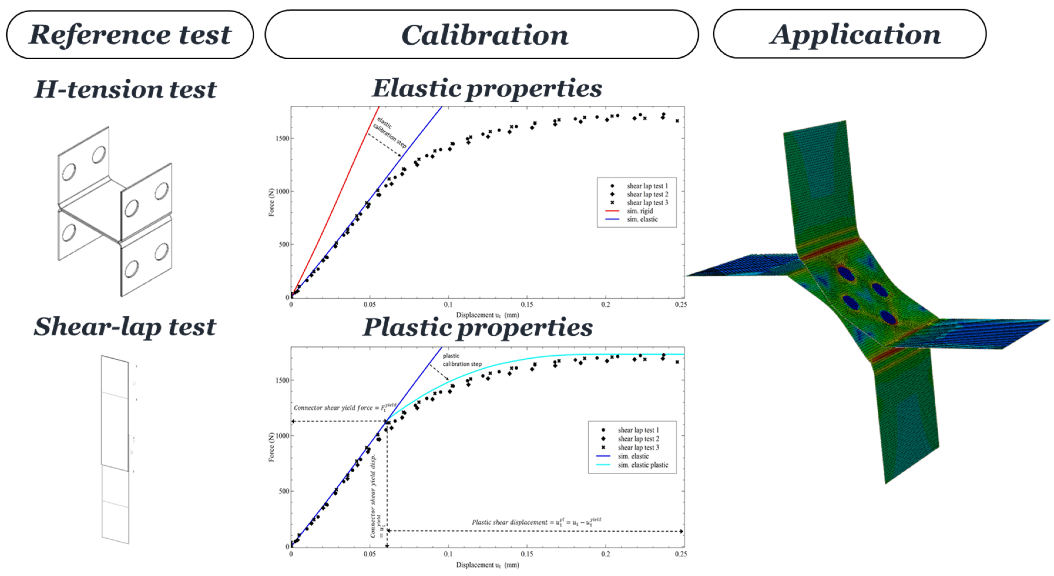
To calibrate the equivalent model as proposed by Breda et al. [7] (Figure 1), a H-tension test and a shear lap test were executed with the considered material and tool combination. The displacements of the specimen were captured using an extensometer. Each test was repeated 5 times to ensure it’s reproducibility. The force-displacement response was captured for each test and used as elastic and plastic calibration data for the model. The obtained calibration parameters were used in the application model: a modified Arcan test containing multiple clinched joints.
2.2. Modified Arcan Test
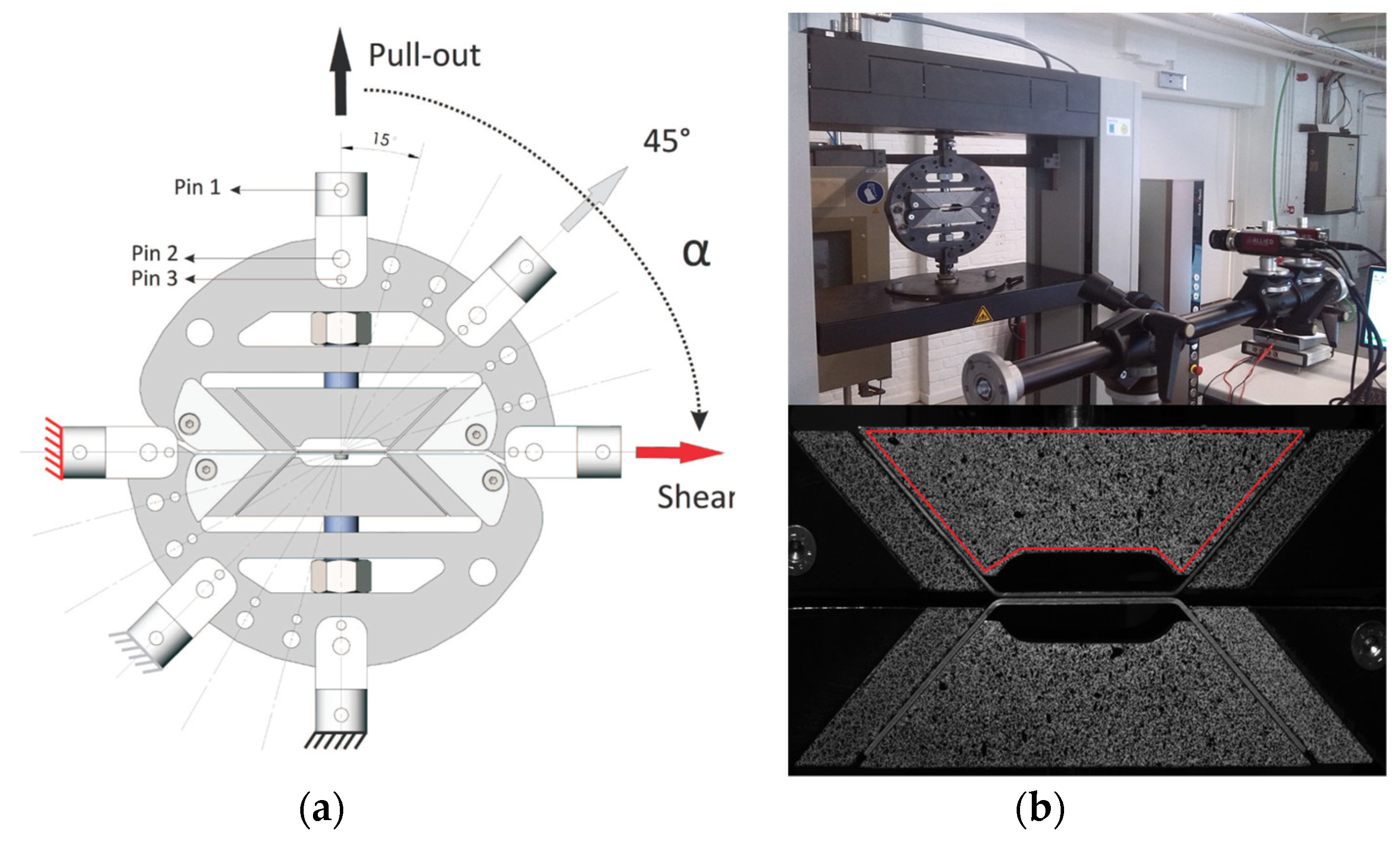
To subject a combination of loads onto the joints, a modified Arcan set-up was used as proposed by Coppieters et al. [8]. The device consists of two disk halves, clamping the clinched specimen. The modified Arcan test can be mounted under different angles in a standard tensile machine, controlling the shear/pull-out ratio onto the joint (Figure 2). For this work, the Arcan fixture was mounted using an angle of 45°, allowing shear and pull-out forces onto the joint. Because of practical reasons, the use of an extensometer was not possible. The displacements of each disk halve were therefore captured using Digital Image Correlation (DIC) [9]. DIC is an optical-numerical technique which tracks displacements with the use of a speckle pattern which is applied to the region of interest.
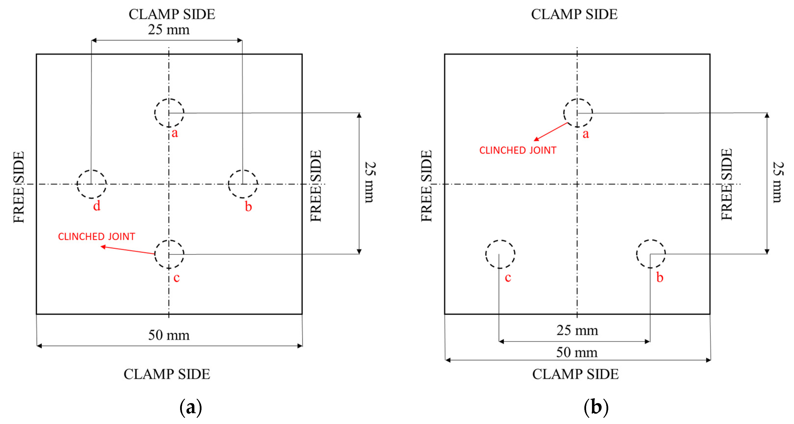
To validate if the force distribution over the different joints can be reproduced accurately with the proposed model, both a symmetrical and asymmetrical pattern were used (Figure 3). The force displacement response and the maximum force for each configuration was determined experimentally. The force displacement results up to maximum force were compared with the numerical model of the Arcan test, which uses the calibrated equivalent model to represent the clinched joints. The numerical model was built using S4R shell elements with a size of 1 mm.
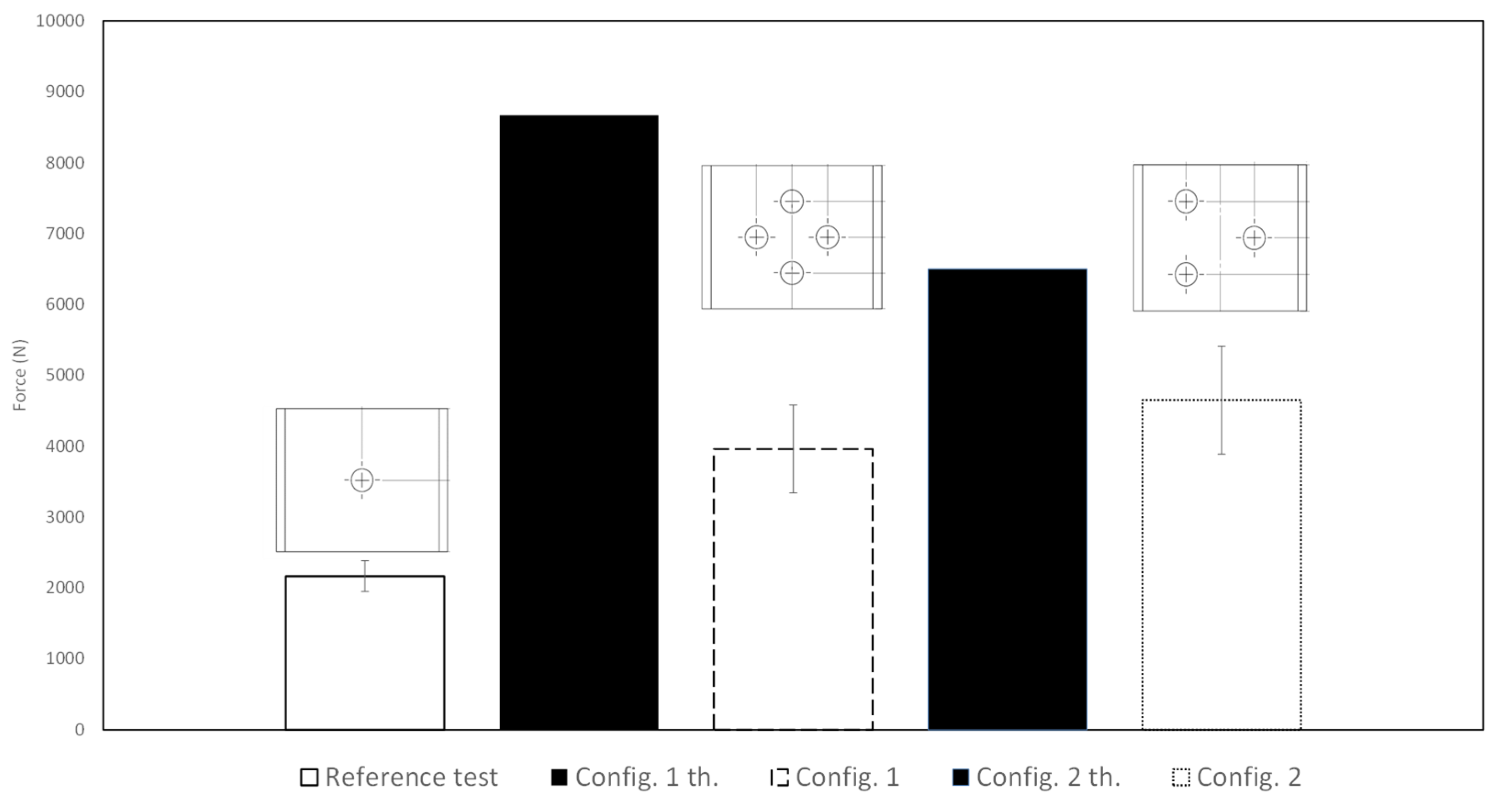
The strength of a single joint inside the modified Arcan device with a load ratio of 45° has been tested as a reference strength (Figure 5). To estimate the strength of multiple joint in configurations, following simple formulae was used to estimate the maximum force resistance for each configuration:
Fth,total= Fsingle × i
With Fth,total as the expected total strength of the joints, Fsingle the strength experimentally tested for one joint and i the total number of joints.
3. Results and Discussion
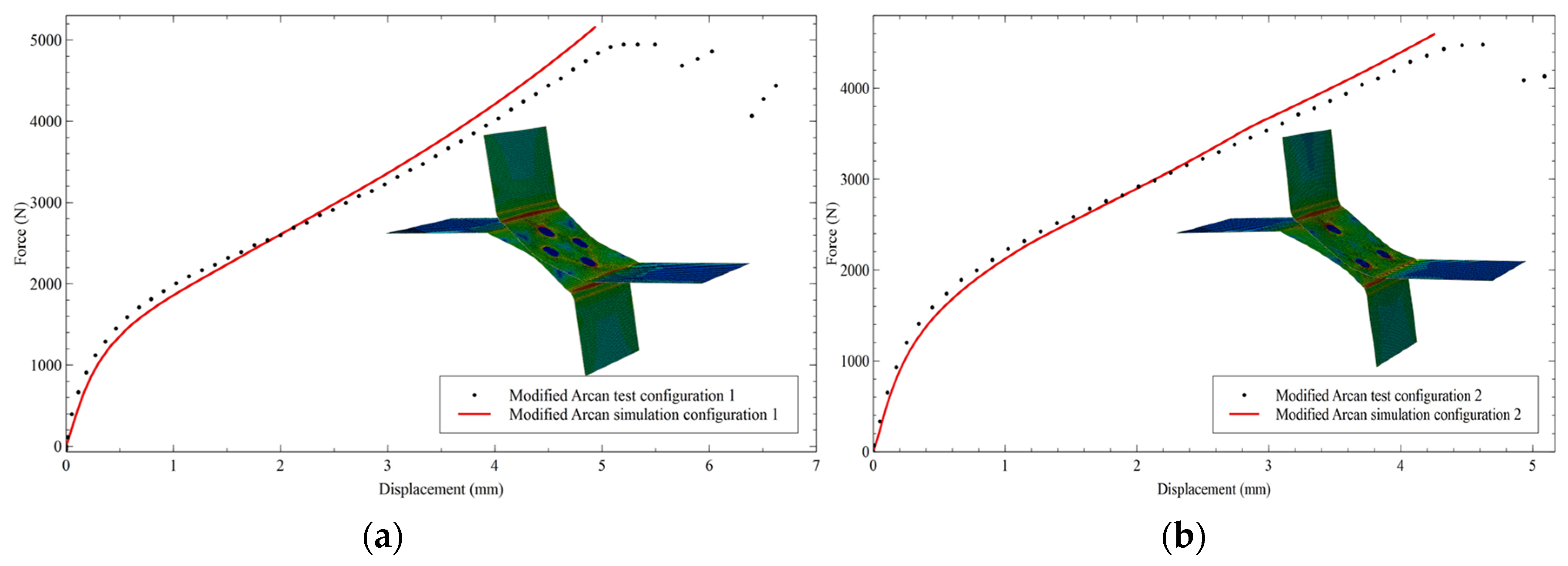
The experimental and simulation results can be found in Figure 4. It can be concluded that for both configurations, the model is able to reproduce the mechanical behaviour of the joint under a combination of peel, shear and pull-out loads and this up to maximum force. As the model is calibrated using the pure shear and pull-out behaviour of the joints, no interaction effect of the joints seems to influence it’s mechanical deformation behaviour up to maximum force.
However, if the maximum forces for each configuration are plotted next to the theoretic value, it can be concluded that some effects due to the positioning of the clinch affects its maximum resistance (Figure 5). A first effect is the presence of peel moments which reduces the maximum resistance of the clinch. The average experimental maximum force for configuration 1 is less than half the theoretical or expected value. For configuration 1 this is due to clinch d and b (Figure 3) which take most of the loads acting onto the specimen. The presence of peel moments on these joints strongly reduces the resistance capability for this configuration. The experimental resistance for configuration 2 is approximately one third less than expected. The forces for this configuration are more distributed over all three joints. Nevertheless, peel moments are induced in every joint reducing its strength resistance with approximately one third of the estimated resistance.
4. Conclusions
The equivalent model for a single clinched joint proposed by Breda et al. [7] is able to reproduce the general deformation behaviour up to maximum force of multiple clinched joints exposed to mixed mode loads. There is no indication that joint interaction affects this general behaviour. Nevertheless, the presence of peel moments does affect the maximum resistance of the joint. This effect should be investigated in future work as in practice (because of geometrical and/or esthetic limitations), it is not always possible to avoid these peel loads onto the joint. These experiments show, that for the development of design resistance rules for clinched joints, further investigation is required in this regard. Research on the effect of peel moments onto the maximum resistance of the clinched joint is currently lacking in literature. In view of design rules, correction factors/equations for peel loads should be determined.
Author Contributions
A.B. wrote the paper and performed all experiments. S.C. and D.D. are supervisors on this work.
Acknowledgments
The presented results are part of the CORNET research project Standardization of Flow Curve Determination for Joining by Forming funded by the program for Industrial Research (IGF) of the Federal Ministry of Economics and Technology Germany and the Belgian government agency Flanders Innovation & Entrepreneurship (VLAIO).
Conflicts of Interest
The authors declare no conflict of interest.
References
- Couchman, G.; Cecconi, A.; Ristori, F.; Salvatore, W.; Ioannidis, C.; Palamas, J.; Ryan, I.; Baraka, S.; Schneider, R.; Sedlacek, G.; Montonen, T.; et al. Design Tools and New Applications of Cold Formed Steel in Buildings; European Commision: Brussels, Belgium, 2000. [Google Scholar]
- Jaspart, J.-P.; Meyer, T.; Mononen, T.; Schneider, R.; Toma, T.; White, D.; Leino, T. Novel Jointing systems for the Automated Production of Light Gauge Steel Elements; ECSC Project ID 7210-PR-252; European Commision: Brussels, Belgium, 2003. [Google Scholar]
- Coppieters, S.; Zhang, H.; Vandermeiren, N.; Breda, A.; Debruyne, D. Process-induced bottom defects in clinch forming: Simulation and effect on the structural integrity of single shear lap specimens. Mater. Des. 2017, 130, 336–348. [Google Scholar] [CrossRef]
- Coppieters, S. Experimental and Numerical Study of Clinched Connections. Ph.D. Thesis, KU Leuven, Ghent, Belgium, 2012. [Google Scholar]
- Davies, R.; Pedreschi, R.; Sinha, B. Moment-rotation behaviour of groups of press-joins in cold-formed steel structures. Thin-Walled Struct. 1997, 27, 203–222. [Google Scholar] [CrossRef]
- Pedreschi, R.; Sinha, B.; Davies, R. End fixity in cold-formed steel sections using press joining. Thin-Walled Struct. 1997, 29, 257–271. [Google Scholar]
- Breda, A.; Coppieters, S.; Debruyne, D. Equivalent modelling strategy for a clinched joint using a simple calibration method. Thin-Walled Struct. 2017, 113, 1–12. [Google Scholar] [CrossRef]
- Coppieters, S.; Lava, P.; Van Hecke, R.; Cooreman, S.; Sol, H.; Van Houtte, P.; Debruyne, D. Numerical and experimental study of the multi-axial quasi-static strength of clinched connections. Int. J. Mater. Form. 2013, 6, 437–451. [Google Scholar] [CrossRef]
- MatchID mbc. Available online: http://www.matchidmbc.be (accessed on 4 April 2018).
Figure 1.
Equivalent modelling strategy overview.

Figure 2.
Modified Arcan device overview: (a) Device overview (b) Experimental set-up (upper) and the attached speckle pattern (lower).
Figure 2.
Modified Arcan device overview: (a) Device overview (b) Experimental set-up (upper) and the attached speckle pattern (lower).

Figure 3.
Overview on the tested configurations: (a) Configuration 1; (b) Configuration 2.

Figure 4.
Numerical and experimental force displacement results: (a) Configuration 1; (b) Configuration 2.
Figure 4.
Numerical and experimental force displacement results: (a) Configuration 1; (b) Configuration 2.

Figure 5.
Expected and experimental maximum values for each configuration.

Publisher’s Note: MDPI stays neutral with regard to jurisdictional claims in published maps and institutional affiliations. |
© 2018 by the authors. Licensee MDPI, Basel, Switzerland. This article is an open access article distributed under the terms and conditions of the Creative Commons Attribution (CC BY) license (https://creativecommons.org/licenses/by/4.0/).
Share and Cite
MDPI and ACS Style
Breda, A.; Coppieters, S.; Debruyne, D. Mechanical Behaviour of Clinched Joints in Configurations. Proceedings 2018, 2, 414. https://doi.org/10.3390/ICEM18-05280
AMA Style
Breda A, Coppieters S, Debruyne D. Mechanical Behaviour of Clinched Joints in Configurations. Proceedings. 2018; 2(8):414. https://doi.org/10.3390/ICEM18-05280
Chicago/Turabian StyleBreda, Andreas, Sam Coppieters, and Dimitri Debruyne. 2018. "Mechanical Behaviour of Clinched Joints in Configurations" Proceedings 2, no. 8: 414. https://doi.org/10.3390/ICEM18-05280