Numerical Investigations on the Fatigue Life of Lean Duplex Transverse Stiffeners in Bridges †


1
Department of Civil Engineering, KU Leuven, 2860 Sint-Katelijne-Waver, Belgium
2
Department of Civil Engineering, KU Leuven, 3000 Leuven, Belgium
3
Department of Materials Engineering, KU Leuven, 9000 Gent, Belgium
*
Author to whom correspondence should be addressed.
†
Presented at the 18th International Conference on Experimental Mechanics, Brussels, Belgium, 1–5 July 2018.
Proceedings 2018, 2(8), 415; https://doi.org/10.3390/ICEM18-05278
Published: 28 May 2018
(This article belongs to the Proceedings of The 18th International Conference on Experimental Mechanics)
Abstract
:Numerical fatigue assessment of welded joints can be done using several approaches. The structural hot spot stress (SHSS) method based on finite element (FE) analysis is considered an effective approach when complex geometries or loading conditions exist. However, in the case of numerical evaluation of the SHSS, the results can differ significantly depending on the FE modelling parameters. In the present paper, the sensitivity of the SHSS to several of these parameters is investigated numerically on one selected critical fatigue-prone detail, namely a transverse weld attachment, in a stainless steel bridge. In parallel a static tensile test performed on the same welded stainless steel detail is presented to measure the SHSS. The strain field near the welded area is measured with digital image correlation (DIC). The experimentally measured and numerically computed SHSS as well as the deduced fatigue lives are then compared and the sources of discrepancy discussed.
1. Fatigue Behavior of Stainless Steel Welded Details
1.1. General Introduction
Recently, there has been a growing interest in the use of stainless steel in modern architecture thanks to its good mechanical strength, corrosion resistance and, of course, low maintenance costs. There exist four different families of stainless steel depending on their microstructure. Duplex grades are characterized by a balanced microstructure made of ferrite and austenite therefore sharing the properties of both the austenitic and ferritic families. The lean duplex grades, namely EN 1.4162 and EN 1.4062 in the latest editions of EN 1993-1-4 (2015) and the Design Manual for Structural Stainless Steel (2017), have lower Nickel and higher Nitrogen content which ensures a large cost reduction when compared to the austenitic and duplex families. Research has shown that the lean duplex grades also have excellent strength, good ductility and high corrosion resistance, comparable to the standard austenitic grades EN 1.4307 and EN 1.4404 [1]. These lean duplex grades are also characterized by good weldability using similar welding processes as for other conventional grades explaining why they are increasingly used in welded constructions in corrosive environments as a good alternative to carbon steel.
In the design of structures exposed to dynamic loading such as bridges, fatigue is an important problem, especially if welded details are present. It is most of the time the governing design criterion for a continuous (open or closed) girder or orthotropic deck bridge due to the presence of several critical welded details. Critical fatigue details have been studied for several existing bridges based on real damage cases [2,3]. In [4], a selection of 8 critical welded bridge details is proposed. The detail studied in this work is part of that list.
Guidance on fatigue verification given in the International Institute of Welding (IIW) documents is one of the most commonly adopted one for welded connections [5]. The EN 1993-1-9 (2005) explicitly states that fatigue design rules are applicable to all grades of structural and stainless steels as long as these materials comply with the toughness requirements provided in the EN 1993-1-10 (2005). Hence, it is applicable to stainless steel structures exposed to cyclic loading. Lean duplex grades submitted to cyclic loading have not yet been studied extensively, but in [6], a series of experimental tests was performed on welded joints made of duplex grade EN 1.4462, showing a longer fatigue life in comparison with carbon steel equivalents.
1.2. The Hot Spot Stress Method
There are numerous fatigue assessment methods for welded joints such as the nominal stress approach, the effective notch stress approach and the fracture mechanics. The structural hot spot stress (SHSS) method among others, described in fatigue design books and IIW guidelines [5], has become a very popular fatigue verification technique in case of stress-raising effects resulting from complex loading, weld seams or geometries (such as orthotropic deck or welded girder bridges). It is a method based on the extrapolation of surface stresses, determined experimentally or numerically using FEM, at specific points adjacent to the weld toe, where the fatigue crack initiation is expected to occur. Stress extrapolation is performed via linear or quadratic functions as in Equations (1) and (2) relative to the plate thickness (t), eliminating stress singularities by excluding the stress raising effects of the weld itself [7,8]. For this reason, traditional fatigue design techniques relying on the nominal stress approach are not as effective for complex geometries as the hot spot stress method [9]. The EN 1993-1-9 (2005) allows using the method, but without further guidance.
In cases where the SHSS method is applied based on a numerical evaluation of the stress using FEM, the accuracy of the results can heavily depend on the FE model characteristics. Numerous studies emphasize the sensitivity of the hot spot stress and, therefore, the fatigue life prediction, to model parameters such as element type, mesh size and mesh type [7,8,9,10,11].
2. Design and Fabrication of the Tested Sample
2.1. Design Based on FE Sensitivity Analysis
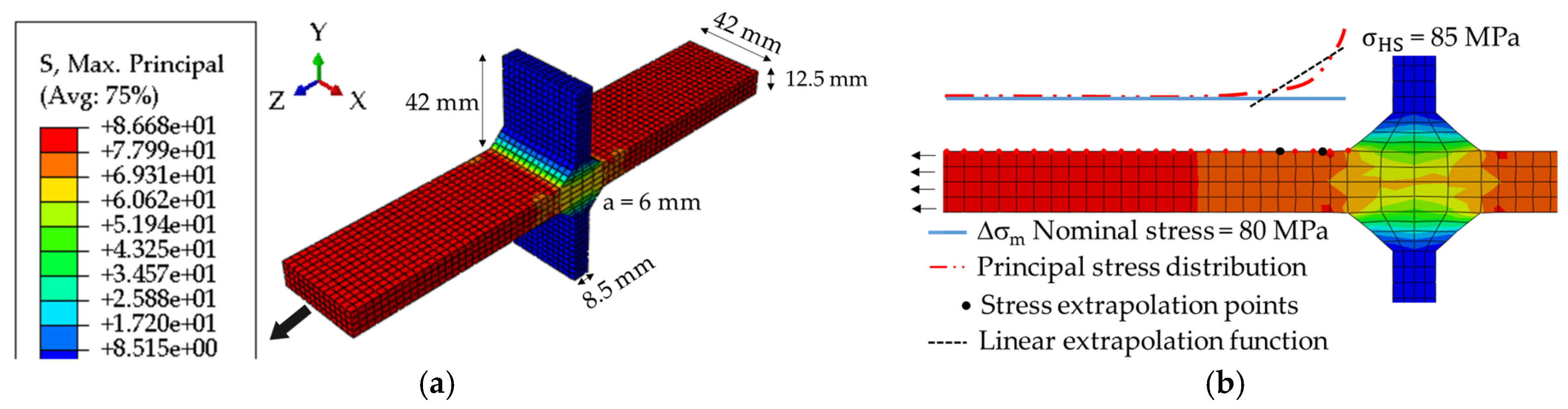
In the present paper, a transverse stiffener made of EN 1.4162 is studied. Although this detail is one of the most common fatigue-prone details in bridges, it is needed due to the susceptibility of slender webs to shear buckling. The design of the test piece has been performed following the SHSS method. In the reference model, the boundary conditions (BCs) having been chosen such that the piece is subjected to uniform tension, resulting in a nominal stress range in the flange corresponding to the detail category FAT 80. The reference model built with the optimal recommended parameters is composed of 8-noded linear solid elements with reduced integration. As outlined in the IIW guideline, fine meshes have been defined with element sizes not larger than 0.4 times the plate thickness; a linear elastic material behaviour is used (E = 200 GPa for EN 1.4162). A linear extrapolation function has been used for computing the SHSS at the weld toe. The final geometry of the model of the detail together with the evaluated SHSS can be seen in Figure 1.
The sensitivity analysis investigates several FE parameters such as: mesh size (coarse vs. fine); element type (linear 8-node vs. quadratic 20-node); shell vs. solid; integration method (reduced vs. full); detail length (100 mm, 200 mm and 300 mm); extrapolation method for the SHSS (linear vs. quadratic); joint type (T-joint vs. cruciform); fillet weld angle (30°, 45° and 60°); weld throat thickness (a = 3 mm vs. a = 6 mm); stiffener thickness (ts = 6 mm, 8 mm and 10 mm); base plate thickness (tp = 8 mm, 10 mm and 12 mm); base plate width (wp = 42 mm vs. 60 mm). The analyses were performed using Abaqus/Standard. As an example, for the design against fatigue, the selection of the mesh size in the IIW guideline is limited to a coarse or fine mesh (element size relative to plate thickness ≤0.4 t and ≤1.0 t respectively). Herein, three meshes, from coarse to very fine (element size varying between ≤12.5 mm and ≤1 mm), were studied and the maximum relative difference in the assessed hot spot stresses is 5.5% (σhs,1mm = 85 MPa, σhs,12.5mm = 80.5 MPa). When similar investigations are performed for the rest of the parameters, it was found that the maximum, resp. minimum, relative variation of the SHSS is 7.7% (it occurs when full integration technique is used instead of reduced integration), resp. 0.1% (when throat thickness varies between 3 and 6 mm).
2.2. Fabrication and Welding Parameters
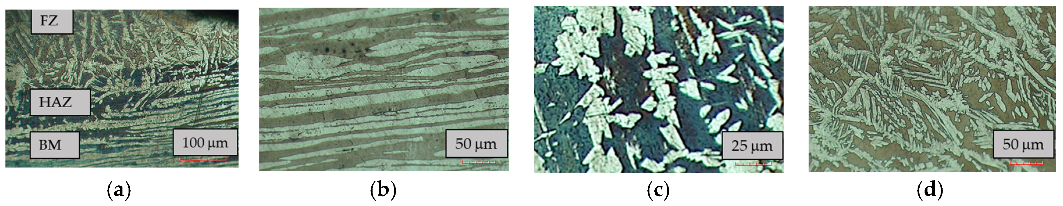
The designed test pieces have been assembled using the gas metal arc welding (GMAW) process producing the fillet welds of a cruciform joint. For duplex stainless steels, the balance of the microstructure is maintained essentially by limiting the heat input between 0.5–1.5 kJ/mm and inter-pass temperature at 150 °C. The balance between the ferrite and austenite phases ensures a good mechanical strength and good corrosion resistance [12]. The chosen filler material was Avesta LDX 2101 with 1.0 mm solid wire. The welding was performed semi-automatically in the Welding Center of KU Leuven on Technology Campus De Nayer. The measured welding parameters are as follows: voltage 10 V; current 198 A; wire speed 10.6 m/min., travel speed 3.90 mm/s.; pulse time 2.1 ms.; pulse frequency 160 Hz.; heat input 1.2 kJ/mm. The preliminary test pieces were visually inspected on inadequate or excessive penetration, mismatch, undercut, surface cracks and inclusions. According to EN ISO 5817, the quality level turned out to be B referring to the highest quality. Microstructural investigation was then achieved by cutting, polishing and etching the welded samples (see ferrite in dark and austenite in white contours in Figure 2). The microscopic images taken in the base metal (BM), heat affected zone (HAZ) and fusion zone (FZ) were processed according to ASTM E562, and the resulting ferrite content was compared to the recommendations as shown in Table 1 [13].
3. Experimental Determination of the Hot Spot Stress
3.1. Test Arrangement and Geometric Imperfection
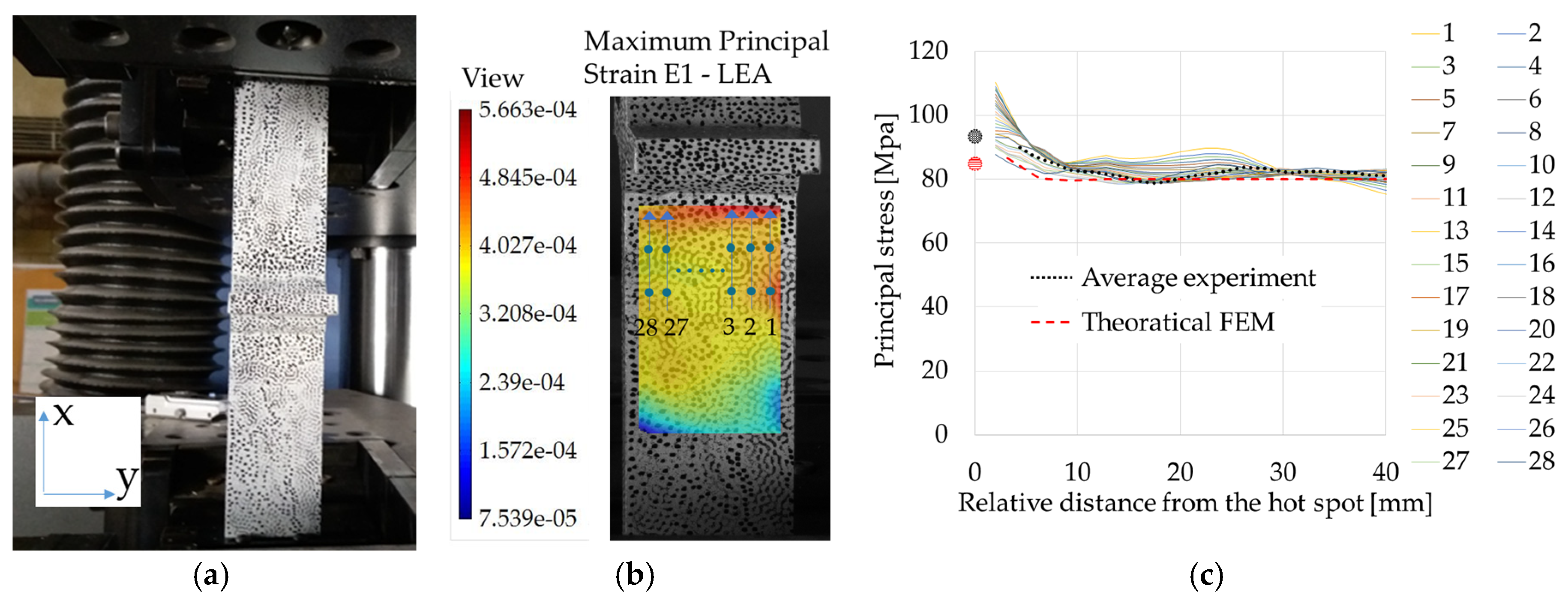
A static tensile test was performed on the welded specimen in the Construction Laboratory of KU Leuven on Technology Campus De Nayer to determine the SHSS. The test was carried out on an Instron 1500HDX series tensile bench. A displacement-controlled testing procedure was applied following the recommendations of EN ISO 6892-1 with a strain rate of 0.00007 s−1 up to 43 kN (where SHSS is reached), then 0.00025 s−1 until failure. Stereo-vision digital image correlation (DIC) was used during the test to capture the full displacement field on one side of the sample. The processing of the measured data from DIC was performed using MatchID [14]. The initial geometry of the welded specimen was also measured with DIC by taking images on both sides of the specimen (Figure 3).
3.2. Comparison of the Measured and Computed Hot Spot Stress
The strain distribution near the weld bead can be seen in Figure 4. The applied load corresponds to 43 kN which leads to a uniform stress distribution of 80 MPa—the nominal stress range of the detail category—away from the weld toe. This can be seen in Figure 4b with an equivalent principal strain of 4.027 × 10⁻⁴ on the base plate. Based on 28 selected stress extrapolation paths, the principal stress distribution relative to the weld toe together with the average of those are compared to the computed SHSS from a theoretical FEM in which no imperfections were included (Figure 4c).
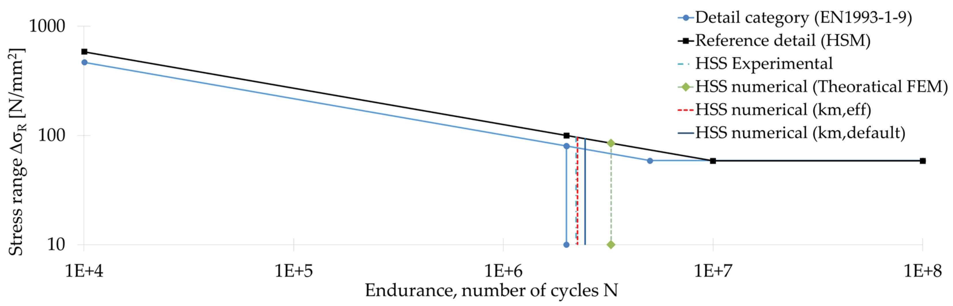
The fatigue life of the welded detail was calculated based on the numerical SHSS using the numerical recommended parameters [5]. The fatigue resistance of the detail is assessed by calculating the number of cycles that it can withstand and by comparing it with 2 × 10⁶ cycles, corresponding to the nominal stress range (detail category). The endurance of the details is determined using the reference Wöhler (SN) curves proposed in the IIW guideline representing, as closely as possible, the actual detail. Based on the reference details, one can formulate the endurance of the assessed detail deriving the number of cycles corresponding to the calculated hot spot stress. An example of this comparison can be seen in Figure 5 together with a summary of all the results in Table 2.
3.3. Fatigue Strength Modification Factor Due to Misalignment (km)
The IIW guideline refers to the fatigue strength modification due to misalignment based on an effective magnification factor km taking into account the presence of secondary shell bending stresses. This can have an influence on the fatigue life of the detail. A certain degree of misalignment is already covered in the SN curves (km = 1.05). But, in the case of measured geometric imperfections, the factor needs to be recalculated according to Figure 3 and Equations (3) and (4). Alternatively, km = 1.10 is recommended as a default value. All the results of this second evaluation can be found in Table 2.
where σm is the membrane stress, here 80 MPa i.e., the nominal stress of the detail category.
4. Conclusions
This study revealed that there exists a large difference between experimentally measured SHSS and numerically computed one if the FEM does not embed any geometrical imperfections. This is in compliance with literature in which experimentally measured SHSS are significantly higher than what is predicted using numerical models [10,15]. Most of the research attributes those discrepancies to the level of mesh refinement, the element type or modelling of the weld itself with each of its specific zones (BM, HAZ) having its specific material law. It was shown that the angular misalignment of the base plate induced by welding of the transverse attachments is influencing the theoretical evaluation of the SHSS. When this misalignment is included via the effective stress magnification factor proposed in the IIW guideline, the computed SHSS matches the experimental one. The default value km = 1.10 leads to a fatigue life closer to the experimental one rather than the one based on FEM. However, it is currently not possible to conclude on the accuracy of the methods compared to the actual fatigue life since no dynamic test was so far conducted and no sensitivity inspection was performed for processing parameters of the DIC images. As a part of the future work, fatigue tests will be conducted on the same detail to derive the actual SN curve, then additionally two more static tensile tests will be performed to complete 3 set of experiments placing the cameras closer to the weld seam to measure the strains in a more detailed way.
Acknowledgments
The first author is funded by the Impulsfonds for the PhD project “3E160992” at KU Leuven. We would like to present our gratitude to Outokumpu for granting EN 1.4162 material for this research.
Conflicts of Interest
The authors declare no conflict of interest.
References
- Wei, Z.; Laizhu, J.; Jincheng, H.; Hongmei, S. Study of mechanical and corrosion properties of a Fe-21.4Cr-6Mn-1.5Ni-0.24N-0.6Mo duplex stainless steel. Mater. Sci. Eng. 2008, 497, 501–504. [Google Scholar] [CrossRef]
- Lukić, M.; Al-Emrani, M.; Aygül, M.; Bokesjö, M.; Urushadze, S.; Frýba, L.; Škaloud, M.; Collin, P.; Nilsson, M.; Eichler, B.; et al. Bridge Fatigue Guidance—Meeting Sustainable Design and Assessment (BRiFaG); Research Fund for Coal and Steel (RFCS): Brussels, Belgium, 2013. [Google Scholar]
- Pedro, J.O.; Reis, A.; Baptista, C. High strength steel (HSS) S690 in highway bridges: Comparative design. In Proceedings of the Eurosteel, Copenhagen, Denmark, 13–15 September 2017. [Google Scholar]
- Karabulut, B.; Lombaert, G.; Debruyne, D.; Rossi, B. Optimized design and life cycle cost analysis of a duplex welded girder bridge. In Proceedings of the International Symposium on Life-Cycle Civil Engineering, Ghent, Belgium, 28–31 October 2018. [Google Scholar]
- Hobbacher, A.F. Recommendations for Fatigue Design of Welded Joints and Components, 2nd ed.; International Institute of Welding (IIW): Paris, France, 2016. [Google Scholar]
- Zilli, G.; Maiorana, E.; Peultier, J.; Fanica, A.; Hechler, O.; Rauert, T. Application of Duplex Stainless Steel for Welded Bridge Construction (BRIDGEPLEX); Research Fund & Coal and Steel (RFCS): Brussels, Belgium, 2008. [Google Scholar]
- Fricke, W. Fatigue analysis of welded joints: State of development. Mar. Struct. 2003, 16, 185–200. [Google Scholar] [CrossRef]
- Niemi, E.; Fricke, W.; Maddox, S.J. Fatigue Analysis of Welded Components: Designer’s Guide to the Structural Hot Spot Stress Approach, 2nd ed.; International Institute of Welding (IIW): Paris, France, 2018. [Google Scholar]
- Aygül, M.; Al-Emrani, M.; Urushadze; S. Modelling and fatigue life assessment of orthotropic bridge deck details using FEM. Int. J. Fatigue 2012, 40, 129–142. [Google Scholar] [CrossRef]
- Lee, J.; Seo, J.; Kim, M.; Shin, S.; Han, M.; Park, J. Comparison of hot spot stress evaluation methods for welded structures. Int. J. Nav. Archit. Ocean Eng. 2010, 2, 200–210. [Google Scholar] [CrossRef]
- Liu, R.; Liu, Y.; Ji, B.; Wang, M.; Tian, Y. Hot spot stress analysis on rib-deck welded joint in orthotropic steel decks. J. Constr. Steel Res. 2014, 97, 1–9. [Google Scholar] [CrossRef]
- Kotecki, D.J. Some pitfalls in welding of duplex stainless steels. Soldagem Inspeção 2010, 15, 336–343. [Google Scholar] [CrossRef]
- Fortan, M.; Dejans, A.; Debruyne, D.; Rossi, B. The strength of stainless steel fillet welds using GMAW. In Proceedings of the Stainless Steel in Structures: Fifth International Experts Seminar, London, UK, 18–19 September 2017. [Google Scholar]
- MatchID Software. Available online: http://www.matchidmbc.be (accessed on 8 April 2018).
- Poutiainen, I.; Tanskanen, P.; Marquis, G. Finite element methods for structural hot spot stress determination—A comparison of procedures. Int. J. Fatigue 2004, 26, 1147–1157. [Google Scholar] [CrossRef]
Figure 1.
FEM of the designed test piece: (a) Principal stress results; (b) Calculation of the SHSS.
Figure 1.
FEM of the designed test piece: (a) Principal stress results; (b) Calculation of the SHSS.

Figure 2.
Microstructure of EN 1.4162 specimen: (a) General view; (b) BM; (c) HAZ—0.08 mm; (d) FZ.

Figure 3.
Geometric imperfections: (a) Out of plane straightness of the front view; (b) Horizontal axis straightness of the side view; (c) Vertical axis straightness of the side view; (d) Formulation for km.
Figure 3.
Geometric imperfections: (a) Out of plane straightness of the front view; (b) Horizontal axis straightness of the side view; (c) Vertical axis straightness of the side view; (d) Formulation for km.
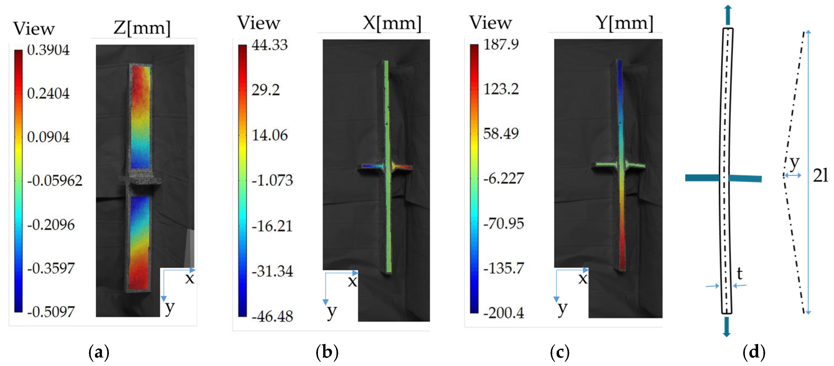
Figure 4.
Experimental setup: (a) View of the cameras; (b) Extrapolation paths for the measurement of hot spot stress; (c) Stress extrapolation paths for the measurement of hot spot stress.
Figure 4.
Experimental setup: (a) View of the cameras; (b) Extrapolation paths for the measurement of hot spot stress; (c) Stress extrapolation paths for the measurement of hot spot stress.

Figure 5.
Fatigue endurance of the analysed detail based on SHSS method.


Table 1.
Ferrite content measurement of the EN 1.4162 specimen.
| Welding Zone | Ferrite Content (%) | Standard Deviation [2σ] | Suggested Ferrite Content [%] |
|---|---|---|---|
| B.M | 54 | 54 ± 7 | 40 to 60 |
| H.A.Z | 66 | 66 ± 8 | 25 to 75 |
| F.Z | 53.6 | 53.6 ± 8 | 25 to 60 (GMAW) |
Table 2.
Summary of the results.
| Hot spot Stress [σHS] | Linear [MPa] | Fatigue Life [N] | Comparison to the Experiment |
|---|---|---|---|
| Average experiment | 96.5 ± 4 1 | 2.2 × 10⁶ | - |
| Numerical (theoretical FEM) | 85 | 3.3 × 10⁶ | +3% |
| Modified SHSS (km,eff) | 96 | 2.3 × 10⁶ | +0.1% |
| Modified SHSS (km,default) | 93 | 2.4 × 10⁶ | +0.7% |
1 2σ standard deviation.
© 2018 by the authors. Licensee MDPI, Basel, Switzerland. This article is an open access article distributed under the terms and conditions of the Creative Commons Attribution (CC BY) license (https://creativecommons.org/licenses/by/4.0/).
Share and Cite
MDPI and ACS Style
Karabulut, B.; Lombaert, G.; Debruyne, D.; Rossi, B. Numerical Investigations on the Fatigue Life of Lean Duplex Transverse Stiffeners in Bridges. Proceedings 2018, 2, 415. https://doi.org/10.3390/ICEM18-05278
AMA Style
Karabulut B, Lombaert G, Debruyne D, Rossi B. Numerical Investigations on the Fatigue Life of Lean Duplex Transverse Stiffeners in Bridges. Proceedings. 2018; 2(8):415. https://doi.org/10.3390/ICEM18-05278
Chicago/Turabian StyleKarabulut, Burak, Geert Lombaert, Dimitri Debruyne, and Barbara Rossi. 2018. "Numerical Investigations on the Fatigue Life of Lean Duplex Transverse Stiffeners in Bridges" Proceedings 2, no. 8: 415. https://doi.org/10.3390/ICEM18-05278