Experimental Investigation on Crack Growth in Pre-Notched Concrete Beams †


Department of Structural, Geotechnical and Building Engineering, Politecnico di Torino,Corso Duca degli Abruzzi 24, 10129 Torino, Italy
*
Author to whom correspondence should be addressed.
†
Presented at the 18th International Conference on Experimental Mechanics (ICEM18), Brussels, Belgium, 1–5 July 2018.
Proceedings 2018, 2(8), 429; https://doi.org/10.3390/ICEM18-05287
Published: 1 June 2018
(This article belongs to the Proceedings of The 18th International Conference on Experimental Mechanics)
Abstract
:It is well-known that failure of unreinforced, pre-notched concrete beams in bending is mainly governed by the tensile strength (“ductile” behaviour) or by the fracture toughness (brittle behaviour) depending on the geometrical scale (beam size), and the value of the relative notch depth. In particular, relatively large beams made of high-strength concrete and with a small relative notch depth, show a brittle structural behaviour (unstable crack propagation); whereas relatively small beams made of low-strength concrete and with a large relative notch depth, show a relatively ductile structural behaviour (stable crack propagation). In this contribution, the damage progress, due to crack formation and propagation, in unreinforced, pre-notched concrete beam specimens, tested in three-point bending, is analysed by the Acoustic Emission (AE) and Digital Image Correlation (DIC) techniques. Beams with rectangular cross-section were considered. A relative notch depth (a/d) equal to 0.5 is assumed in all cases. The loading process was operated by controlling the vertical displacement. The specimens were instrumented by four transducers measuring the vertical displacements in correspondence to the supports and at mid-span, and the Crack Mouth Opening Displacement (CMOD). In addition, two AE transducers were located near the notch to acquire the AE signals originated by material damage. Moreover, the evolution of the deformation process was monitored around the notch by a DIC system, therefore obtaining the time evolution of strains. By analysing the acquired data, a correlation between the AE signals registered and the displacements/strains measured at several points was looked for. Furthermore, the fracture energy of each specimen was evaluated, according to RILEM recommendation, based on the measured load–deflection curves. Scale effects on fracture energy, bending strength, and AE energy per unit area were investigated.
1. Introduction
In the present work, three-point bending tests were performed on plain concrete pre-notched specimens of different sizes, investigating the damage process that takes place when the dimensional scale is increased, maintaining all the remaining parameters unchanged [1]. RILEM Recommendation [2,3] was followed for the testing procedure and for the evaluation of Fracture Energy and bending strength. During the tests, two non-destructive techniques for damage monitoring were used: Acoustic Emission (AE) analysis and 2D Digital Image Correlation (DIC).
As is well-known, the AE technique is based on the acquisition of the ultrasonic signals generated by crack formation and extension in the bulk of the material [4,5,6]. Unlike Fracture Energy, that is dissipated in an invasive fractal domain, AE energy seems to be emitted in a lacunar fractal domain: this difference in the fractal physical dimensions indicates the un-correlation between dissipated and emitted energies [7,8,9].
On the other hand, DIC is an innovative non-contact optical technique for measuring displacement and strain based on accurate 2D and 3D tracking and registration of changes in images [10,11].
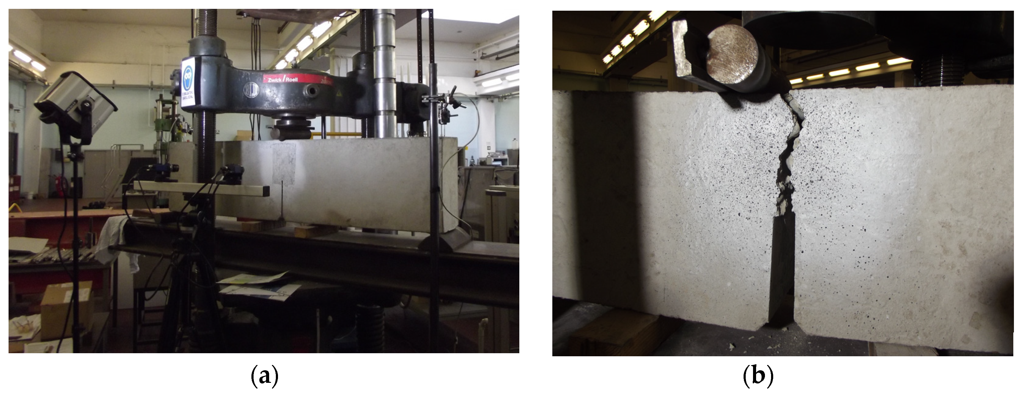
For three-point bending testing, specimen sizes prescribed by [2,3] were taken into account (Table 1). Specimens were tested by servo-hydraulic universal testing machines: an MTS with a maximum loading capacity of 100 kN was used for testing the smaller beams (depth = 100 mm); the tests on the beams of larger sizes were conducted—for convenience in terms of experimental set-up—using a Baldwin testing machine with maximum loading capacity of 500 kN (Figure 1). Three tests were conducted on specimens with d = 100 mm; two tests on beams with d = 200 mm; one test on a beam with d = 300 mm; and three tests on beams with d = 400 mm. The mechanical properties of the concrete constituting the beams are the following: mass density ρ = 2310 kg/m3; cubic compression strength Rc = 26.4 MPa; cylindrical compression strength fc = 21.9 MPa; average tensile strength fct = 2.4 MPa; average elastic modulus Ec = 30,570 MPa.
All the specimens were tested until the final failure was reached. During the tests, Crack Mouth Opening Displacement (CMOD) was measured using a clip-on strain gage applied to the notch mouth; the vertical displacement of the beam mid-section was taken equal to the stroke of the machine hydraulic jack. Piezoelectric resonant AE sensors were applied on the specimen surface in order to capture AE signals [5]. The data were acquired by an 8-channel national instruments digitizer, setting the acquisition threshold to 2 mV, and adopting a sampling frequency of 1 Msample/s. The registered signals were amplified by 60 dB before processing.
On the other hand, DIC measurements were performed on two beams, one with d = 300 mm and the other with d = 400 mm, by means of VIC-2D system by Correlated Solutions. Figure 2a shows the set-up of a test with the DIC apparatus, whereas Figure 2b shows a detail around the mid-span section, cracked after final collapse.
In the following, we briefly report on some of the results obtained. More details will be given in future contributions.
2. Results
In order to define scale-invariant material properties, the fractal nature of the damaged microstructure in quasi-brittle and disordered materials must be considered [12,13,14]. It is known that: for tensile (bending) strength, the actual dimension of material ligament at peak stress is (lacunar domain); for fracture energy, the actual dimension of fracture surface at failure is (invasive domain). An interesting result is obtained here for AE energy per unit area, i.e., it is dissipated on a lacunar fractal domain ().
Figure 3 shows the renormalized load–deflection curves. The load is nondimensionalised as: , where is the renormalized tensile (bending) strength and is the corresponding fractal exponent. The deflection is nondimensionalised as: . The value of is, in this case, equal to 0.36, as will be shown hereafter.
In Figure 4, the bending strength vs. specimen size (beam depth) values, corresponding to all the tests, are reported in a bi-logarithmic diagram. The relevant fractal scaling law reads: , with , ().
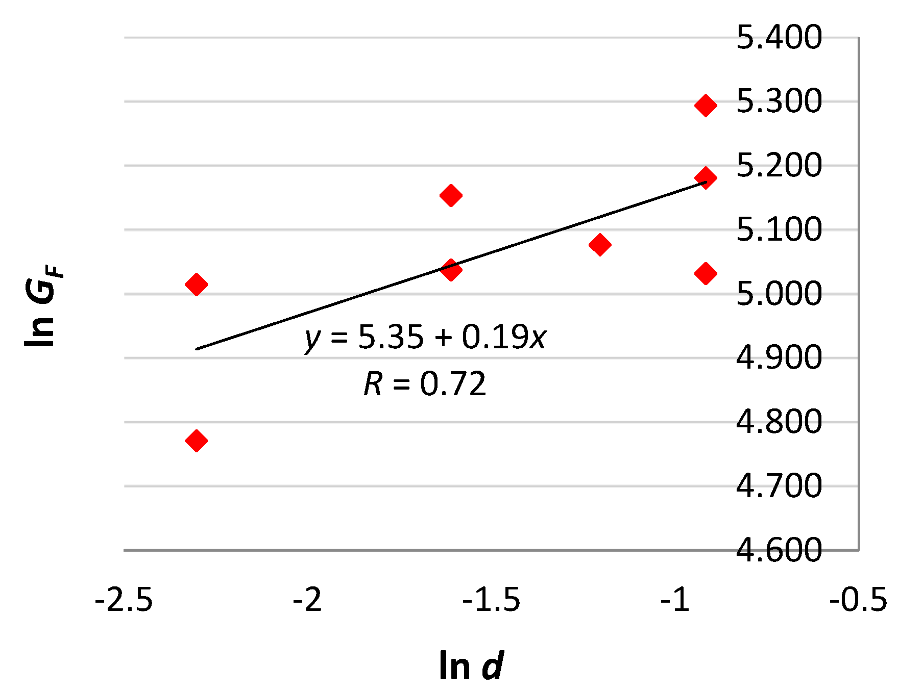
Figure 5 shows the fracture energy vs. beam depth diagram. The corresponding fractal scaling law is , with , ().
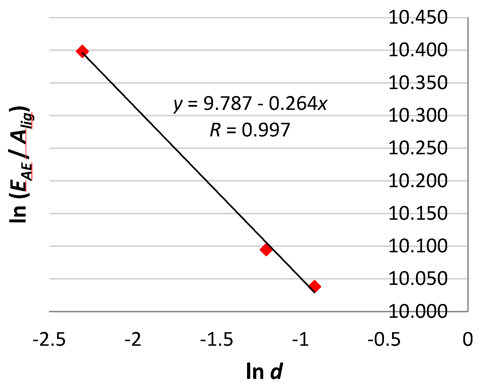
Figure 6 shows the AE energy per unit area vs. beam depth diagram. The fractal scaling law is , with , ().
In Figure 7, the load and cumulated AE energy vs. time diagrams of three tests are superimposed.
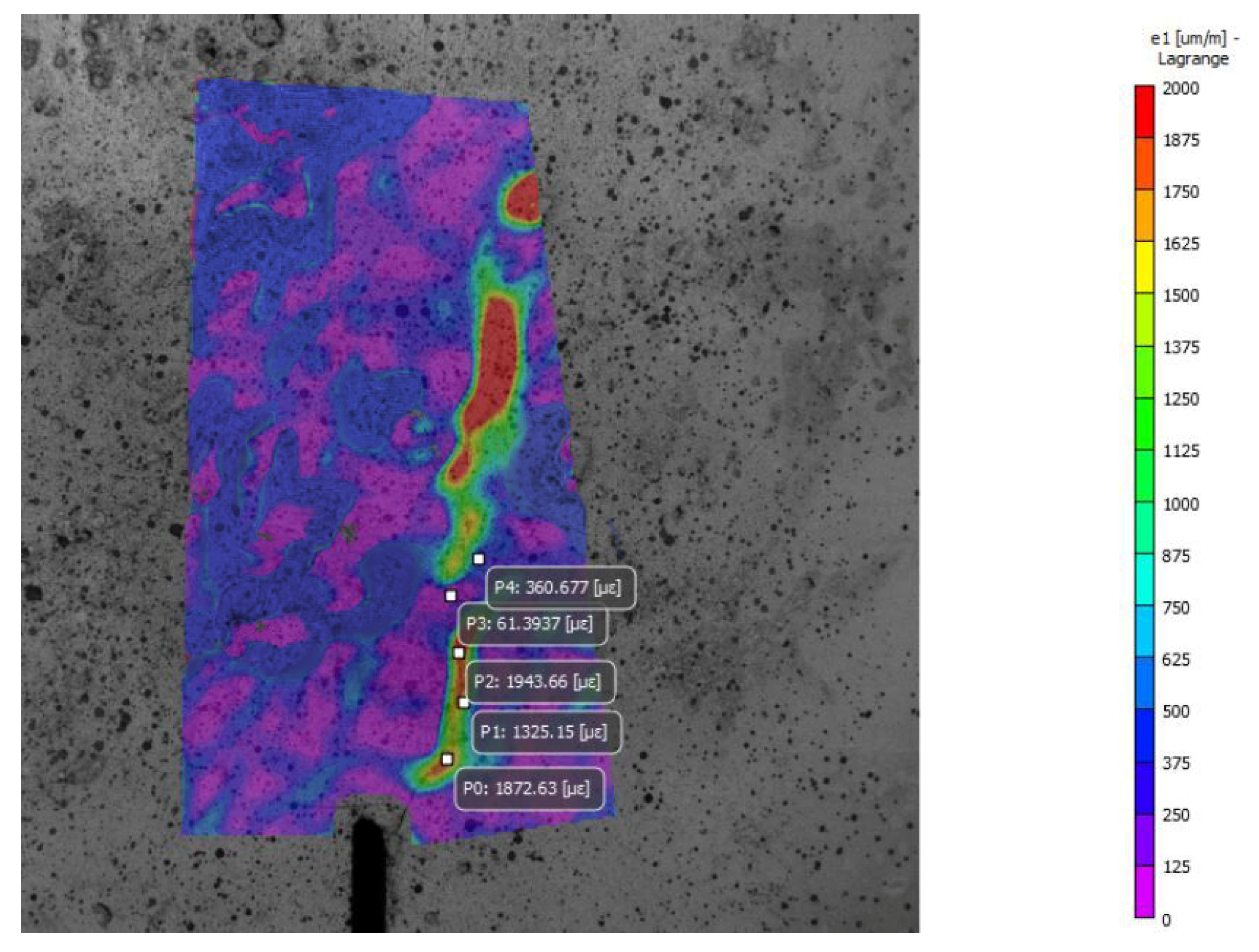
Lastly, the time evolution of strains at several points around the pre-notched section, and in particular along the crack, was obtained from DIC results. An example of data is shown in Figure 8, where principal strain values at five points (P0-P4) are superimposed to the relevant strain contour plot (along principal direction 1), for a test made on a beam with d = 400 mm. In future works, the damage progress monitored by DIC will be correlated with RA (AE signal rise time/the peak amplitude), AF (AE ringdown counts/the duration time), b-value, and other AE parameters.
3. Conclusions
Scale effects on fracture energy, bending strength and AE energy per unit area were observed by performing three-point bending tests on plain concrete specimens of four different sizes. The fractal model was applied to define scaling laws and renormalized scale-invariant values for the above-mentioned parameters. Results indicate the absence of correlation between dissipated (fracture) and emitted (AE) energies. The damage process around the pre-notched section was monitored by AE and DIC techniques, thus offering the possibility to correlate the two sets of data. Deeper investigations on the latter point will be the objective of future contributions.
Author Contributions
G.L., G.P., F.A., A.C. performed the experiments, analyzed the data, and wrote the paper.
Conflicts of Interest
The authors declare no conflict of interest.
References
- Carpinteri, A. Mechanical Damage and Crack Growth in Concrete. Plastic Collapse to Brittle Fracture; Martinus Nijhoff Publishers: Dordrecht, The Netherlands, 1986. [Google Scholar]
- RILEM TC50-FMC Draft Recommendation. Determination of fracture energy of mortar and concrete by means of three-point bend tests on notched beams. Mater. Struct. 1985, 18, 285–290. [Google Scholar]
- RILEM TC QFS Recommendation. Quasibrittle fracture scaling and size effect—Final report. Mater. Struct. 2004, 37, 547–568. [Google Scholar]
- Lacidogna, G.; Manuello, A.; Niccolini, G.; Accornero, F.; Carpinteri, A. Acoustic emission wireless monitoring of structures. In Acoustic Emission and Related Non-destructive Evaluation Techniques in the Fracture Mechanics of Concrete; Ohtsu, M., Ed.; Chapter 2; Woodhead Publishing: Cambridge, UK, 2015; pp. 15–40. [Google Scholar]
- Lacidogna, G.; Accornero, F.; Carpinteri, A. Masonry structures. In Innovative AE and NDT Techniques for On-site Measurement of Concrete and Masonry Structures (RILEM); Ohtsu, M., Ed.; Chapter 3; Springer: Heidelberg, Germany, 2016; pp. 27–46. [Google Scholar]
- Carpinteri, A.; Lacidogna, G.; Invernizzi, S.; Accornero, F. The Sacred Mountain of Varallo in Italy: Seismic risk assessment by Acoustic Emission and structural numerical models. Sci. World J. 2013, 2013, 170291. [Google Scholar] [CrossRef] [PubMed]
- Carpinteri, A.; Accornero, F. Multiple snap-back instabilities in progressive microcracking coalescence. Eng. Fract. Mech. 2018, 187, 272–281. [Google Scholar] [CrossRef]
- Lacidogna, G.; Accornero, F.; Corrado, M.; Carpinteri, A. Crushing and fracture energies in concrete specimens monitored by Acoustic Emission. In Proceedings of the 8th International Conference on Fracture Mechanics of Concrete and Concrete Structures, FraMCoS 2013, Toledo, Spain, 11–14 March 2013; pp. 1726–1736. [Google Scholar]
- Carpinteri, A.; Lacidogna, G.; Corrado, M.; di Battista, E. Cracking and crackling in concrete-like materials: A dynamic energy balance. Eng. Fract. Mech. 2016, 155, 130–144. [Google Scholar] [CrossRef]
- Sutton, M.A.; Orteu, J.J.; Schreie, H. Image Correlation for Shape, Motion and Deformation Measurements. Basic Concepts, Theory and Application; Springer: New York, NY, USA, 2009. [Google Scholar]
- Aggelis, D.G.; Verbruggen, S.; Tsangouri, E.; Tysmans, T.; van Hemelrijck, D. Characterization of mechanical performance of concrete beams with external reinforcement by acoustic emission and digital image correlation. Constr. Build. Mater. 2013, 47, 1037–1045. [Google Scholar] [CrossRef]
- Carpinteri, A. Decrease of apparent tensile and bending strength with specimen size: Two different explanations based on fracture mechanics. Int. J. Solids Struct. 1989, 25, 407–429. [Google Scholar] [CrossRef]
- Carpinteri, A. Fractal nature of material microstructure and size effects on apparent mechanical properties. Mech. Mater. 1994, 18, 89–101. [Google Scholar] [CrossRef]
- Carpinteri, A. Scaling laws and renormalization groups for strength and toughness of disordered materials. Int. J. Solids Struct. 1994, 31, 291–302. [Google Scholar] [CrossRef]
Figure 1.
Experimental set-up for three-point bending tests on universal testing machines: (a) specimen with d = 100 mm on MTS machine after final failure; (b) testing set-up on Baldwin machine for specimens with d = 200, 300, and 400 mm.
Figure 1.
Experimental set-up for three-point bending tests on universal testing machines: (a) specimen with d = 100 mm on MTS machine after final failure; (b) testing set-up on Baldwin machine for specimens with d = 200, 300, and 400 mm.
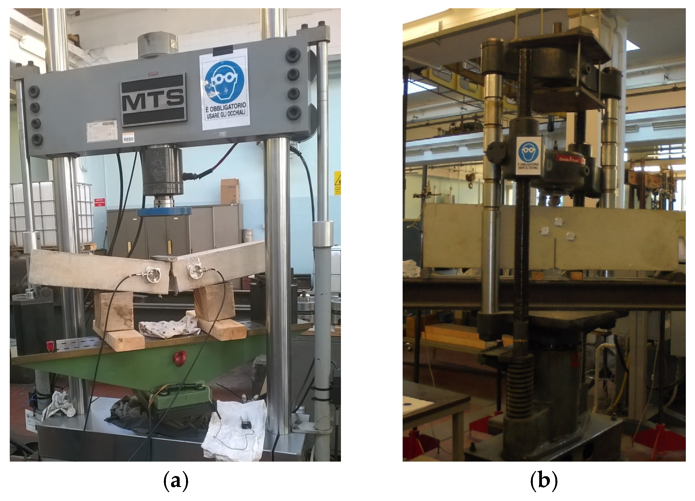
Figure 2.
(a) Experimental set-up for DIC measurements; (b) mid-span region after collapse.

Figure 3.
Renormalized load vs. deflection curves.
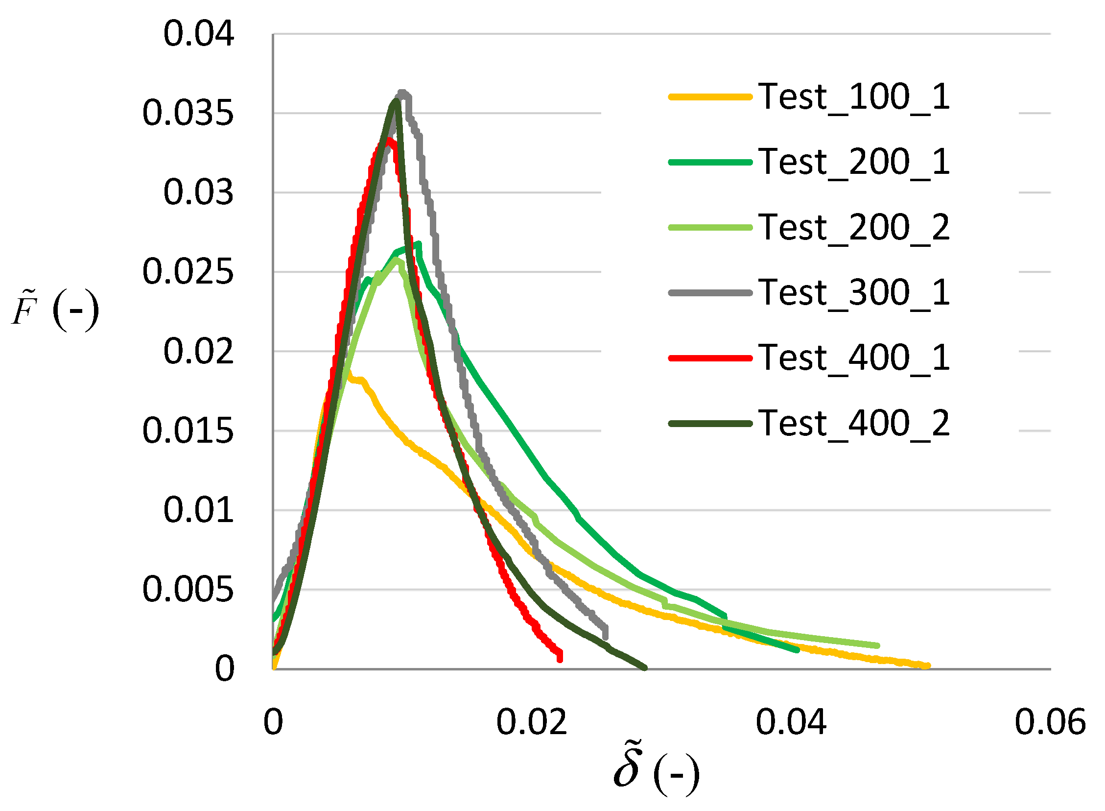
Figure 4.
Bending strength vs. beam depth diagram (R is the Pearson correlation coefficient).
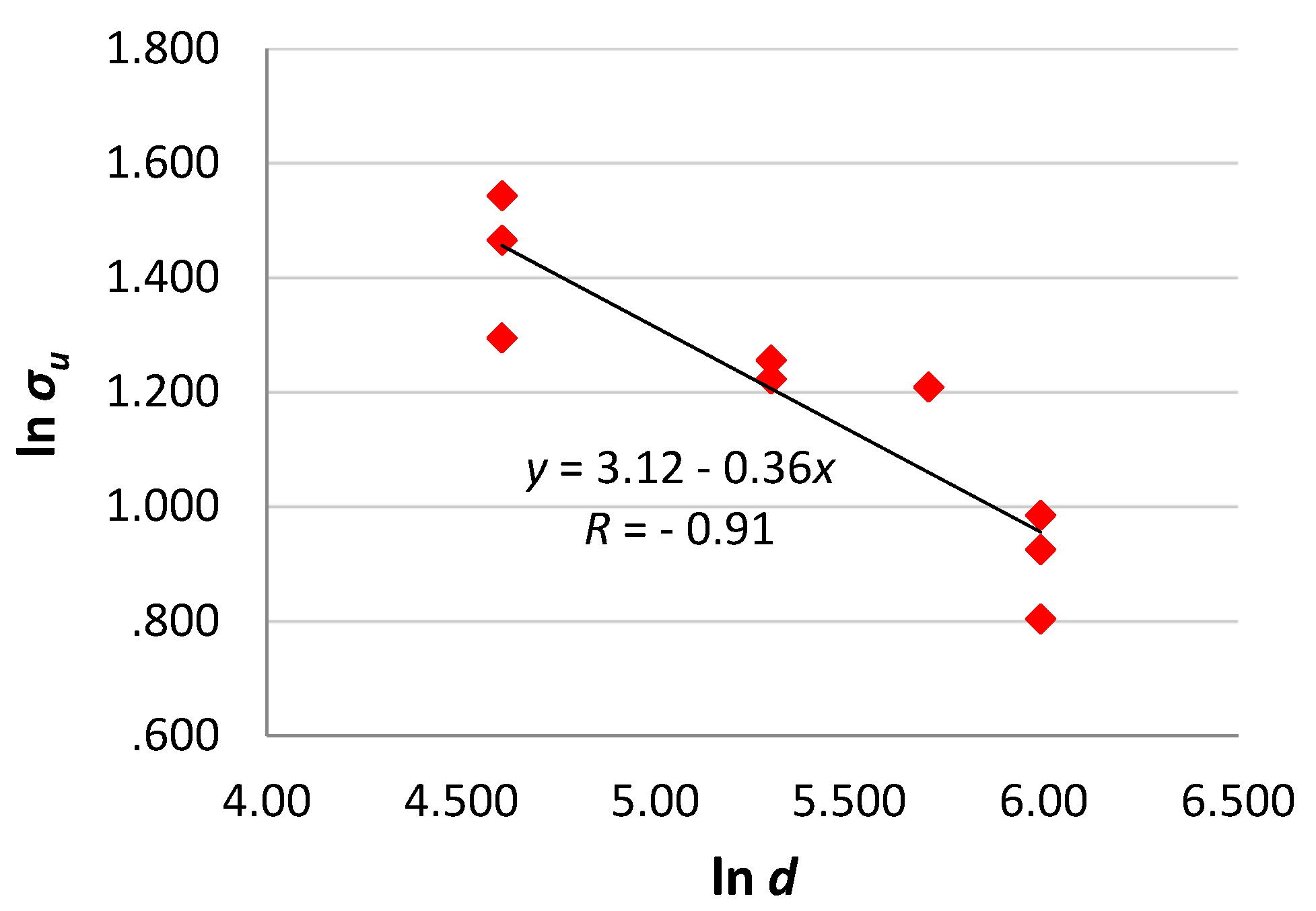
Figure 5.
Fracture energy vs. beam depth diagram (R is the Pearson correlation coefficient).

Figure 6.
AE energy per unit area vs. beam depth diagram (R is the Pearson correlation coefficient).
Figure 6.
AE energy per unit area vs. beam depth diagram (R is the Pearson correlation coefficient).

Figure 7.
Load and cumulated AE events vs. time for (a) d = 100 mm, (b) d = 300 mm, (c) d = 400 mm.
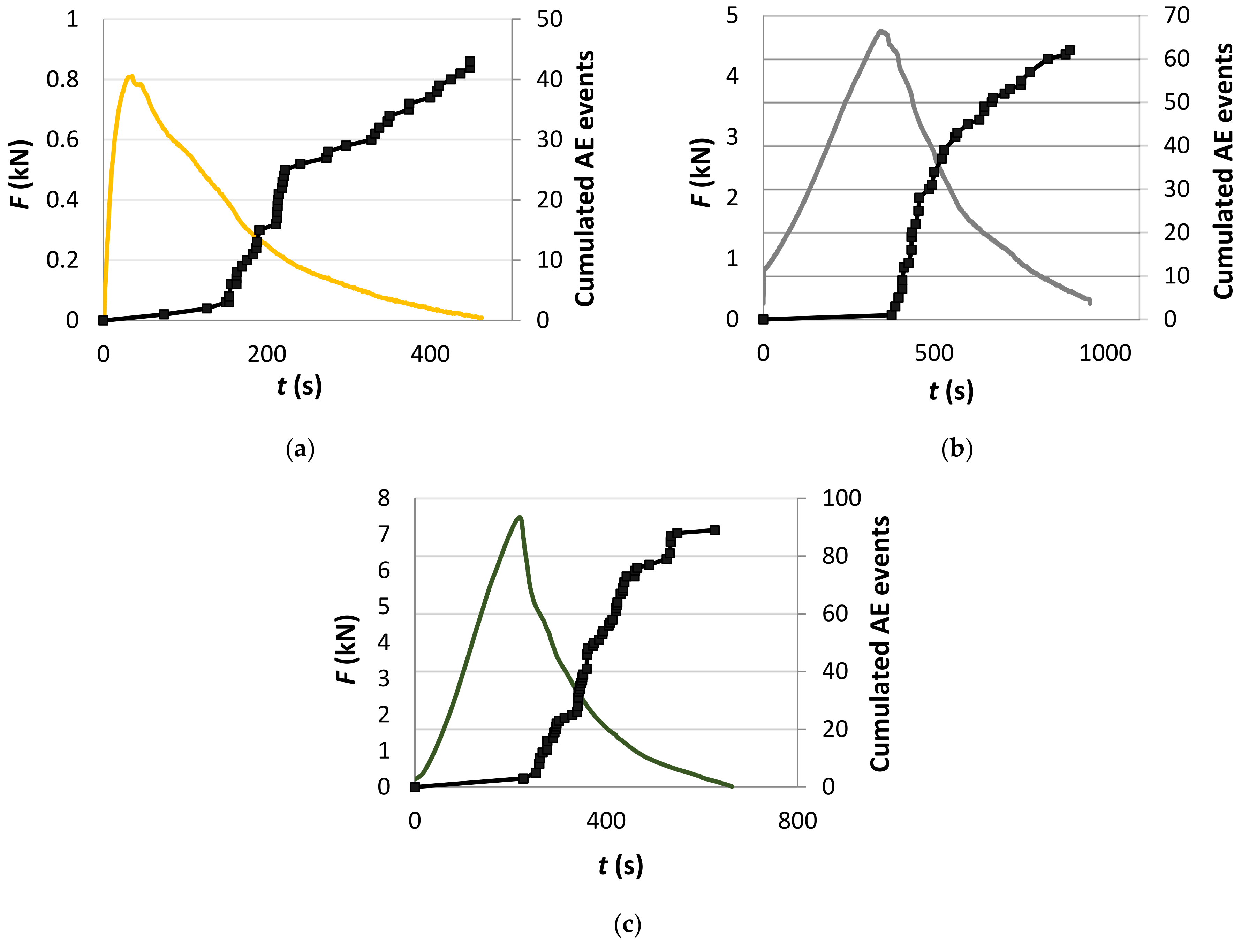
Figure 8.
Example of contour plot and strain values along principal direction 1 obtained by DIC.


Publisher’s Note: MDPI stays neutral with regard to jurisdictional claims in published maps and institutional affiliations. |
© 2018 by the authors. Licensee MDPI, Basel, Switzerland. This article is an open access article distributed under the terms and conditions of the Creative Commons Attribution (CC BY) license (https://creativecommons.org/licenses/by/4.0/).
Share and Cite
MDPI and ACS Style
Lacidogna, G.; Piana, G.; Accornero, F.; Carpinteri, A. Experimental Investigation on Crack Growth in Pre-Notched Concrete Beams. Proceedings 2018, 2, 429. https://doi.org/10.3390/ICEM18-05287
AMA Style
Lacidogna G, Piana G, Accornero F, Carpinteri A. Experimental Investigation on Crack Growth in Pre-Notched Concrete Beams. Proceedings. 2018; 2(8):429. https://doi.org/10.3390/ICEM18-05287
Chicago/Turabian StyleLacidogna, Giuseppe, Gianfranco Piana, Federico Accornero, and Alberto Carpinteri. 2018. "Experimental Investigation on Crack Growth in Pre-Notched Concrete Beams" Proceedings 2, no. 8: 429. https://doi.org/10.3390/ICEM18-05287