Unmanned Aerial Systems for Civil Applications: A Review


1
Geotech Lab—Galician Aerospace Centre (CINAE), School of Energy and Mining Engineering, Unviersity of Vigo, 36310 Vigo, Spain
2
Galician Aerospace Centre (CINAE), Porto do Molle Industrial Park, 36350 Nigran, Spain
*
Author to whom correspondence should be addressed.
Drones 2017, 1(1), 2; https://doi.org/10.3390/drones1010002
Submission received: 10 May 2017
/
Revised: 7 July 2017
/
Accepted: 12 July 2017
/
Published: 13 July 2017
Abstract
:The present work is a review of unmanned aerial systems technology and their subsystems (frame, propellers, motors and batteries, payloads, and data processing). Different applications are evaluated, related to remote sensing, spraying of liquids, and logistics. An overview of the regulatory framework is also developed.
1. Introduction
An unmanned aircraft system (UAS) is defined as a powered aerial vehicle that does not carry a human operator, uses aerodynamic forces to provide vehicle lift, and can fly autonomously or be remotely piloted (RPAS) [1]. UASs have evolved rapidly in recent years due to diverse efforts in the field of electronics, optics, computer science, energy storage, etc. The improving of technologies such as Global Navigation Satellite Systems (GNSS) [2,3,4], Inertial Measurement Units (IMU) [5,6,7,8,9], Light Detection and Ranging (LiDAR) [10,11,12], Synthetic Aperture Radar (SAR) [13,14], imaging sensors [15,16,17,18], and robotics (UAV) [19,20,21,22] has contributed to the progress of UAS technology. UASs allow flight in difficult and inaccessible areas, avoiding risk to the crews of manned aircraft [23].
The first UAS attempts started during World War I when the Dayton-Wright Airplane Company invented an unmanned aerial torpedo that would explode at a preset time. In 1917 the first flight of the Hewitt-Sperry Automatic Airplane occurred (Figure 1), also an aerial torpedo that carried explosives to a target [24,25]. During World War II the first large-scale production drone from Reginald Denny Industries appeared. They manufactured nearly 15,000 drones for the U.S. army to use for training anti-aircraft gunners. McDonnell built a pulsejet-powered target, the TD2d-1 Katydid.
The Cold War also contributed to drone evolution. The first target drone converted for a battlefield unmanned aerial photo-reconnaissance mission was a version of the MQM-57 Falconer (first flight in 1955). The usefulness of UAS for reconnaissance was demonstrated in Vietnam. At the same time, early steps were being taken to use them in active combat at sea and on land. However, UASs would not come into their own until the 1980s. Israel coordinated the use of UAS alongside manned aircraft in 1982 in its war against Syria. Drones from Israel were used as electronic decoys, electronic jammers, and reconnaissance tools. The Predator RQ-1L UAS from General Atomics was the first UAS deployed in the Balkans war in 1995. This trend continued in modern conflicts such as Afghanistan or Iraq from the 2000s up to today.
Although most UAS developments come from the military world, in the last decade UASs have penetrated in civilian applications. This is mainly due to the price lowering and accessibility of technologies such as GNSS, IMU, Electronic Speed Controllers (ESC) for brushless motors, Lithium Polymer (LiPo) batteries, digital imaging, etc. The combination of these technologies with the development of new microprocessors and imaging systems led to civil UAS systems based on fixed and rotatory wings. Multicopters are rotary-wing aircraft with more than two rotors. The great advantage lies in the simplicity of the rotor mechanics required for flight control, in contrast to conventional single- and double-rotor helicopters, which use complex blade rotations. Multicopters control the vehicle motion, only varying the relative speed of each rotor to change the thrust and torque with fixed-pitch blades. The first commercial multicopter appeared in Germany in 2005, developed by Microdrones [26]. Then, many other companies followed in the footsteps of Microdrones and the industrial sector of multicopters quickly expanded. Applications of this technology appeared in the fields of geomatics, precision agriculture, infrastructure monitoring, and logistics. In relation to fixed-wing aircraft systems, the milestones achieved by the Sensefly company should be noted; it has developed small systems for applications in precision agriculture, reaching a very high market share in the last 10 years [27].
2. UAS Classification
UASs typically are classified into six functional categories: target and decoy, reconnaissance, combat, logistics, research and development, and civil and commercial [28]. Civil and commercial UASs are those used by operators dedicated to applications such as professional photography and video, infrastructure inspection, precision agriculture, etc. This area also includes applications related to law enforcement and emergencies. A typical classification according to aircraft weight divides them into micro air vehicles (weighing less than 1 kg), miniature UAS (less than 25 kg), and heavier UAS. However, other classifications exist.
Depending of the aerodynamic flight principle, they are classified as fixed-wing or rotary-wing aircraft.
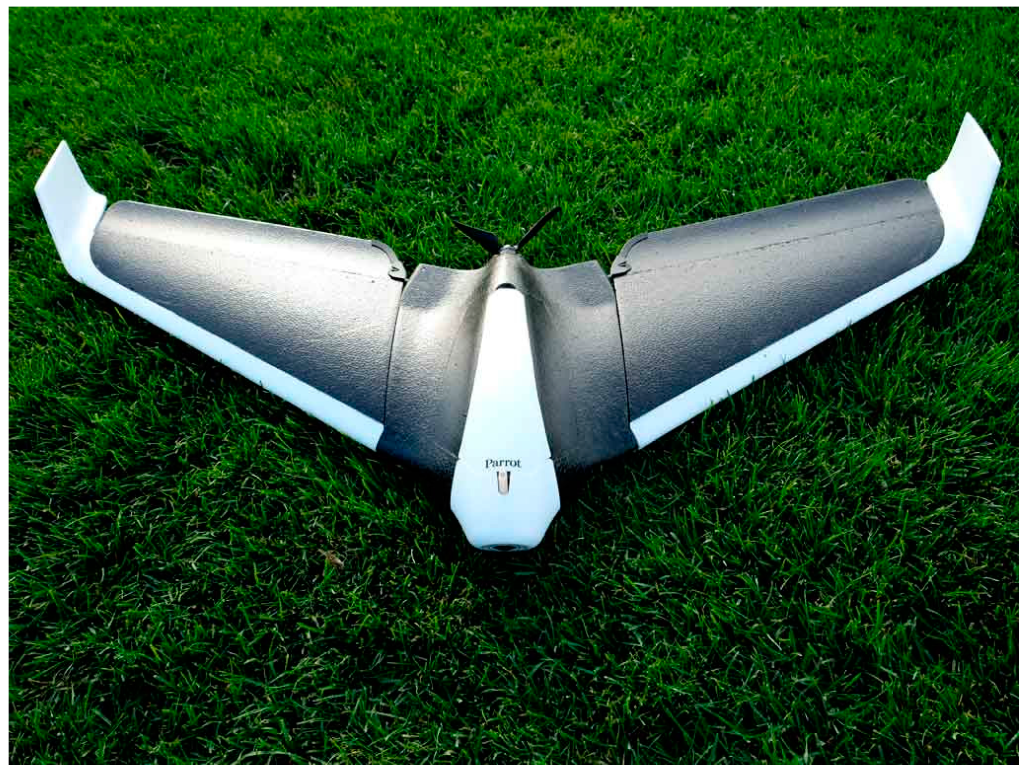
Fixed-wing UAS have a predetermined airfoil that makes flight possible by generating the lift caused by the UAS forward airspeed. Control of the UAS comes from surfaces built on the wing (ailerons, elevators, and rudder). They allow the UAS to turn around the pitch, roll, and yaw angles. The elevator controls the pitch, ailerons control the roll, and the rudder controls the yaw. Figure 2 shows an example of a fixed-wing civil UAS [29,30].
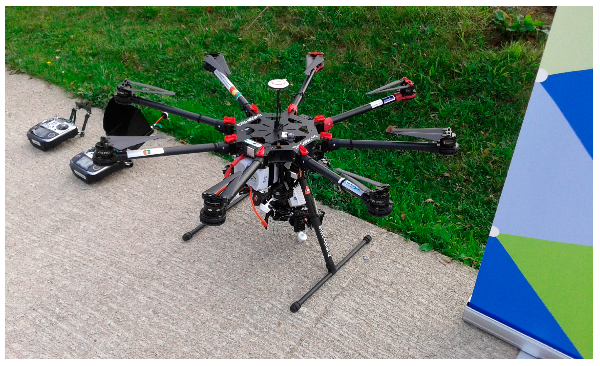
Rotary-wing UASs (Figure 3) consist of a number of rotor blades that revolve around a fixed mast. The aerodynamics of rotor blades is similar to those of a fixed-wing; however, the aircraft can hover and forward movement is not needed to produce lift. The blades themselves are in constant motion, which produces the airflow required to generate the lift. Control of rotary UAS comes from the variation in thrust and torque from the rotors. For example, yaw movement uses the imbalance produced in the yaw axis forces produced by an increasing/decreasing of the speed of a pair of diagonal motors. Multirotor UASs are classified depending on the rotor configurations in tricopters, quadcopters, hexacopters, and octocopters. In terms of reliability, quadcopters have no possibility of landing if one motor fails, while a hexacopter can survive with limited yaw control and octocopters can fly and land with one motor failure.
Rotary-wing UASs allow heavier payload, easier takeoff and landing, better maneuvering than fixed-wing UAS, and the possibility of hovering. However, fixed-wing UASs benefit from a simpler structure, less complicated maintenance, efficient aerodynamics, and longer flight duration and range coverage. The flight time of rotary-wing UASs hardly ever surpasses 30 min with electric motors, while it can easily pass 60 min in fixed-wing UAS. Payloads over 3 kg are common in rotary-wing UASs. However, this payload weight specification is more difficult to achieve in fixed-wing UASs [31,32,33,34,35,36,37,38,39,40,41,42,43,44,45,46,47,48,49,50,51]. Fixed-wing UASs are more often used in the monitoring of large fields, forests, or linear infrastructure (roads or railways). On the other hand, rotary-wing UASs are focused in applications such as infrastructure inspection (bridges, dams, or windmills), monitoring of small fields, and spraying.
Although it does not yet have a very large market share, there are also hybrid systems that combine rotary-wing systems for takeoff and landing and fixed-wing systems for horizontal displacements.
3. UAS Subsystems
3.1. Frame
The frame is the main structural element of UASs. It serves as the main support for other elements such as motors, electronic subsystems, batteries, and payload. Its shape is due to a compromise between a smooth geometry with little aerodynamic resistance and certain needs of resistance and capacity to be able to fulfill its objectives [52,53].
Aerodynamics is more important in fixed-wing UASs than in rotary-wing aircraft. The Blended Wing Body design (BWB), also called flying-wing, offers advantages in aerodynamic and efficiency over the conventional fuselage and wing designs. It also simplifies the control surfaces. A BWB design consists of a modified delta design that blends the wing of the aircraft and body into a smooth configuration. They can be controlled at low-speed flight regimes during takeoff and landing. In addition, they can simply control the aircraft, avoiding elevators and rudders.
A number of aerospace materials are used for fixed-wing and rotary-wing UAS. Low-cost fixed-wing UASs, such as Parrot Disco, use a foam frame, while high-end UASs use materials such as carbon fiber. Rotary-wing UASs use plastic, aluminum, and carbon fiber frames, depending on the quality of the aircraft. Low-cost models such as DJI Phantom use plastic, while, for example, the DJI Inspire or Microdrones use carbon fiber.
It must be emphasized that there are frames that enclose in the interior the most important electronic systems, while in other models the electronics are outside of the frame. The latter are more sensitive to inclement weather (mainly water) and impact.
3.2. Propellers
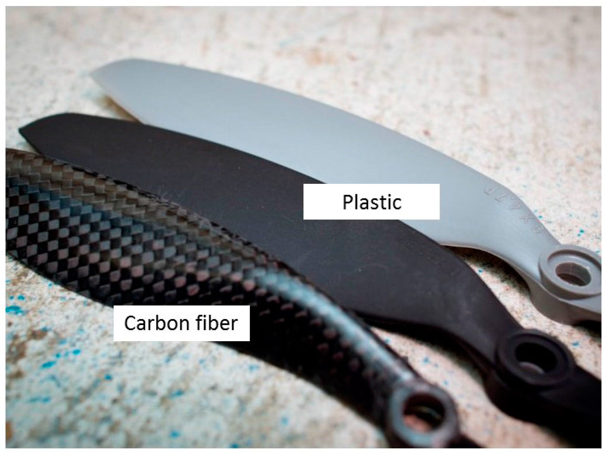
A propeller converts rotational motion into thrust in agreement with the Bernoulli’s principle. Aircraft propellers are characterized by the size, pitch, number of blades, and type of material. Carbon fiber propellers are more expensive than plastic ones and provide better performance (Figure 4). They are more rigid and produce less vibration when spinning. In addition, they are lighter and more durable during small crashes. However, as they are more rigid, the motor bearings support higher impacts during crashes.
Two-blade propellers give more thrust than three- or four-blade propellers, which are more affected by turbulence. Ideally, the most efficient flight consists of the largest propeller diameter turning at the lowest velocity. A single-bladed propeller would be the most efficient, although they are not used because of the dynamic imbalance. Sometimes propellers with three or more blades are used because of space limitations or because propeller blades that are too large result in a higher speed close to supersonic. Speed is thus a tradeoff for efficiency. One example is racing drones, which commonly use three-blade propellers [54,55].
Propellers can also be divided into fixed and adjustable pitch. Civil UAS systems typically use fixed-pitch propellers. Adjustable pitch propellers are sometimes used in helicopter-type UASs with a fueled motor. In this case, the working principle is based on the change of pitch of the propeller blades to absorb the selected motor power for any selected power. Increasing the blade pitch increases the drag, while decreasing the blade pitch decreases the drag.
Many UAS manufacturers recommend foldable propellers. They can minimize damage during problematic landings and improve UAS transportability.
3.3. Motors and Batteries
The strong adoption of multicopters is partly linked to the brushless motors (Figure 5), their easy electronic control, and the development of energy sources based on light batteries. Although there are systems that use fueled motors, in this work the attention is focused on brushless electric motors, which are the most widely used [56,57].
Brushless DC motors are electronically commutated systems. They are powered by a DC electric power source using an integrated inverter, which produces an AC electric signal to drive the motor. Typically, the rotor part consists of a permanent Nd-magnet synchronous motor, and the stator part consists of a series of coils arranged radially. Brushless DC motors appears in the 1960s due to advances in solid-state electronics. They present higher efficiency and lower susceptibility to mechanical wear than brushed motors. In addition, they offer other advantages such as a high torque to weight ratio, reduced noise, and overall reduction of electromagnetic interference.
Brushless motors commute by software implementation using a microcontroller or in digital firmware using a field-programmable gate array (FPGA). They are used in two common electrical winding configurations. The delta configuration connects three windings to each other in a triangle-like circuit. The wye (Y-shaped) configuration connects all the windings to a central point and power is applied to the remaining end of each winding. A motor with windings in delta configuration gives low torque at low speed, but can give a higher top speed. Wye configuration gives high torque at low speed.
The reliability, easy control, and efficient power transmission of brushless motors have contributed greatly to many of the UAS developments in both fixed-wing and rotary-wing systems. Motors must be matched to the propeller that is being used. It is important that the maximum current ratings not be exceeded by trying to get too much power out of them, forcing them to turn too slowly, or they will overheat.
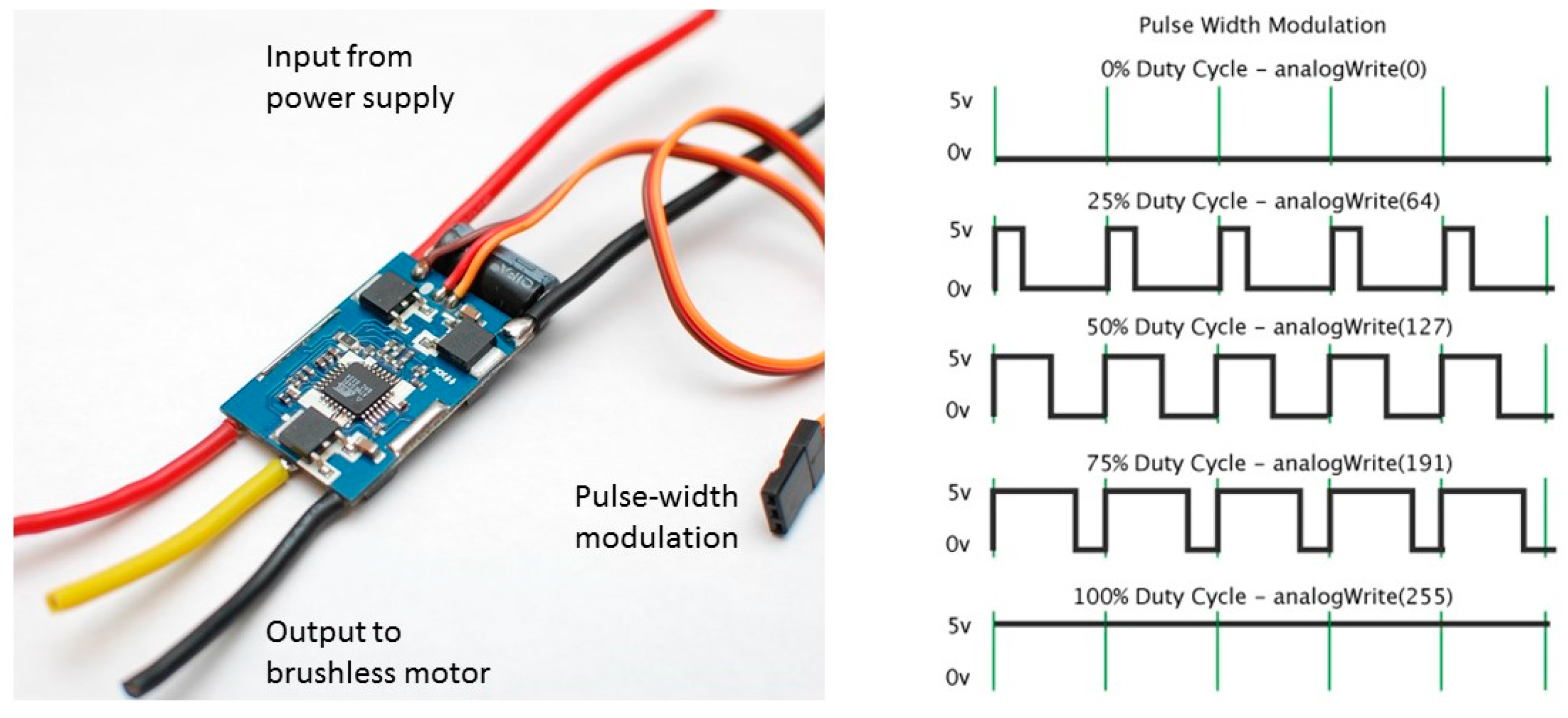
One crucial element related to the brushless motors is the electronic speed controller (ESC) (Figure 6). This controls the rotation frequency of the motors. ESCs are typically rated according to the maximum current. They support NiMH batteries, LiPo batteries, and LFP batteries with a range of input voltage [58,59,60]. The rotation frequency is controlled using pulse width modulation (PWM). PWM is provided by the autopilot control board.
3.4. Flight Time
The maximum flight time of UASs is one of the most active research lines worldwide in relation to UAS technology. Fixed-wing UAS systems can provide higher flight duration because of their aerodynamic performance. In the case of fixed-wing aircraft, it is also possible to integrate energy recovery systems based on solar panels, which results in longer flight duration. Some examples are the Alphabet and Facebook drones, powered with solar energy to deliver high-speed, reliable Internet around the world. On the other hand, rotary-wing systems exhibit more limited flight times and their operations are circumscribed to typically less than 30 min work (Table 1). The motors and batteries of quadrotors represent a total of approximately half of the mass of the system, which negatively affects the flight duration of the quadrotors.
Larger batteries allow longer flight time. However, the increase of flight time is not proportional to the increase of battery size but shows an asymptotic behavior. As the battery gets larger, the increase in flight time becomes ineffective. In addition, the heavier a quadrotor gets, the less agile is. Another important specification to take into account with LiPo batteries is the “C rating.” This is an indicator of the maximum continuous discharge rate of a LiPo battery. For example, a 3S 1000 mAh 20C LiPo pack can draw a maximum recommendable current of 20 A (1000 mAh × 20C). The battery might suffer from overheating when discharging an extremely high current rate.
3.5. Flight Control
A conventional fixed-wing aircraft flight control system consists of flight control surfaces mechanically connected to the respective cockpit controls to define the aircraft direction in flight. These controls include the motor controls that change the plane speed. The manual control can be replaced or assisted by autopilot systems that are based on electronic interfaces. The sensors integrated on the aircraft frame produce electronic signals transmitted to the flight computer that determine how to move the actuators at each control surface to provide the expected response. Autopilots are part of avionics.
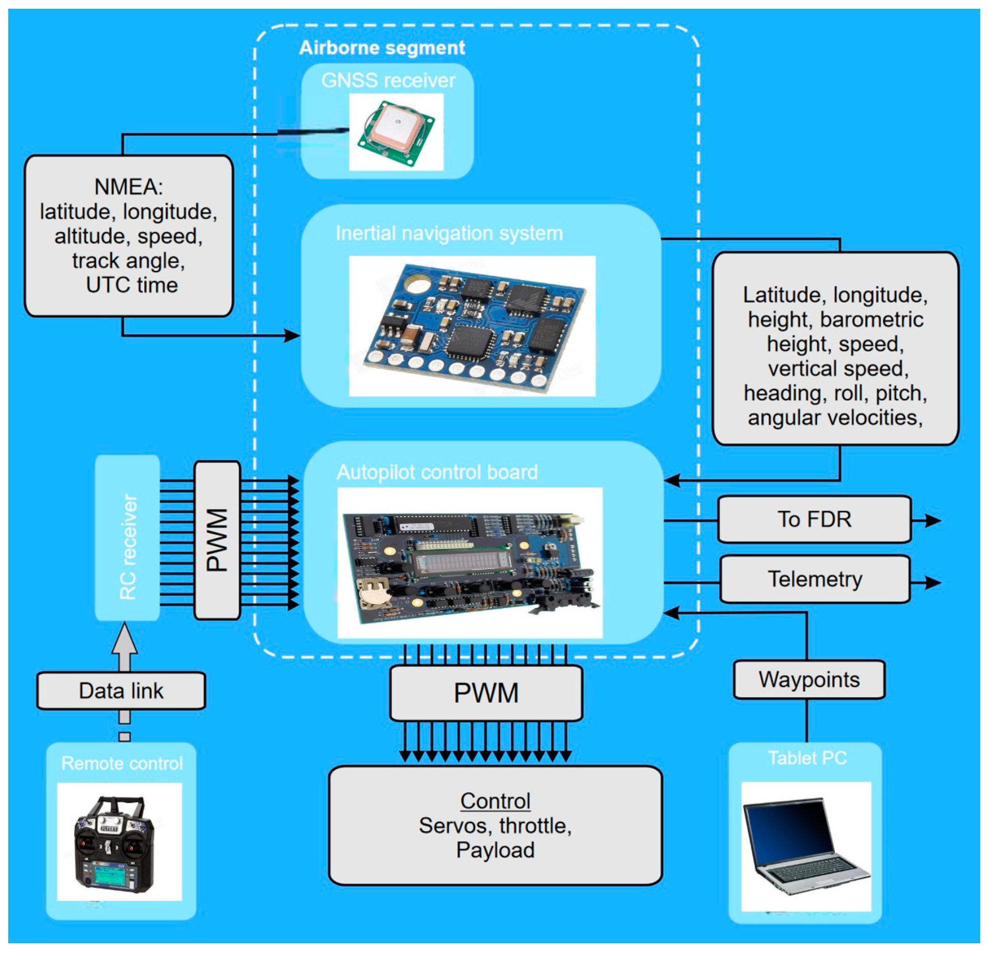
Autopilots are key elements of UASs. They provide semi-autonomous navigation and assist the remote piloting of the aircraft when required [61,62,63]. Figure 7 shows a diagram of the main inputs and outputs of the autopilot. Geopositioning is provided by a GNSS receiver. This information gives latitude, longitude, altitude, speed, track angle, and GNSS time. A UART serial port is typically used to provide the information to the autopilot control board. Positioning information is combined with the attitude of the UAS. Attitude is sensed using an inertial navigation system and provides barometric height, vertical speed, heading, roll, pitch angles, and angular speed. INS combines barometers, accelerometers, gyros, and magnetometers. These data are entered into the autopilot and determine the PWM signal to control the servos (fixed-wing UAS) and ESC (both fixed-wing and rotary-wing UAS). Semi-automated piloting is possible using a remote control. In this case, the autopilot collaborates with the human operator to smooth the piloting requirements. The operator also can use a computer, tablet, or mobile phone to provide GNSS waypoints that can be saved in the autopilot to navigate. There are many software options for mission planning. Figure 8 shows one free software example, the QGroundControl. It provides full flight control and UAS setup for PX4 or ArduPilot. It allows mission planning for autonomous flight, flight map display, video streaming, and support for managing multiple UAS. Table 1 and Table 2 show the specifications of a number of open and closed hardware autopilots. Open hardware autopilots provide full information about the electronic components of which they are composed and the code running on the system. On the other hand, the information provided by the closed hardware autopilots depends on the manufacturer strategy and typically is not open to users.
UAS control is one of the key aspects in system operation as they are severely underactuated systems. For example, quadrotors show six degrees of freedom (three translational and three rotational) and only four independent inputs (thrust from motors). Thus, the solution to achieving six degrees of freedom is the coupling of rotational and translational motion. This coupling and the aerodynamic effects result in highly nonlinear dynamics and a nonlinear control system.
3.6. Payloads and Data Processing
Payload is defined as all the elements of an UAS that are not necessary for flight but are carried for the purpose of fulfilling specific mission objectives. Payloads of civil UAS can be categorized into three main groups: remote sensing, spraying systems for precision agriculture, and logistics.
3.6.1. Remote Sensing
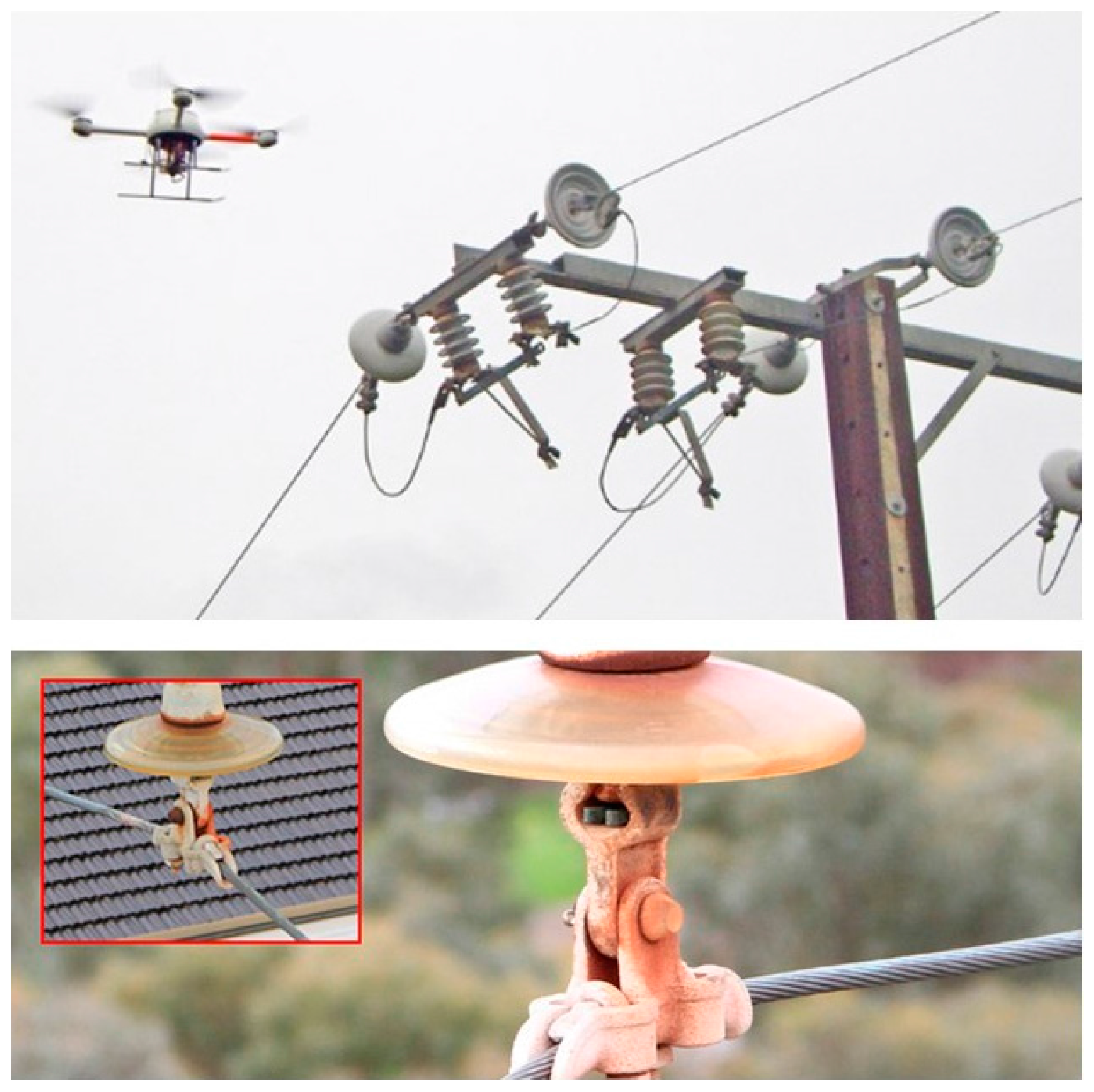
Remote sensing is one of the areas where UAS has found application: aerial imagery to audio-visual production, surveying applications that use photogrammetry to provide orthoimages, and digital elevation models or inspection of large infrastructures such as bridges, windmills, or power lines (Figure 9) [72,73,74,75,76].
Many applications for agriculture such as the monitoring of crop yield estimation or crop identification require near-infrared imaging with multi-spectral or hyper-spectral cameras. Multi-spectral cameras include bands of red, green, and blue, plus the red-edge and near-infrared. In contrast, hyper-spectral imaging involves a greater number of narrower bands (sometimes more than 2000 of them). One example is the Parrot Sequoia multi-spectral sensor. It combines a RGB 16 Mpixel sensor (4608 × 3456 pix) with four single band sensors (green—550 nm, red—660 nm, red edge—735 nm, and near-infrared—790 nm). It also includes GNSS and IMU for positioning and orientation. Sensor calibration and extracting repeatable reflectance values is a complex problem that always requires careful field procedures.
The improvement in embedded computation capabilities and image processing algorithmic contributes to applications related with on-board real time image processing [77]. This opens very interesting fields of work. For example, it allows us to use this information in UAS navigation and decreases the bandwidth needs of the communications data-link with the ground station.
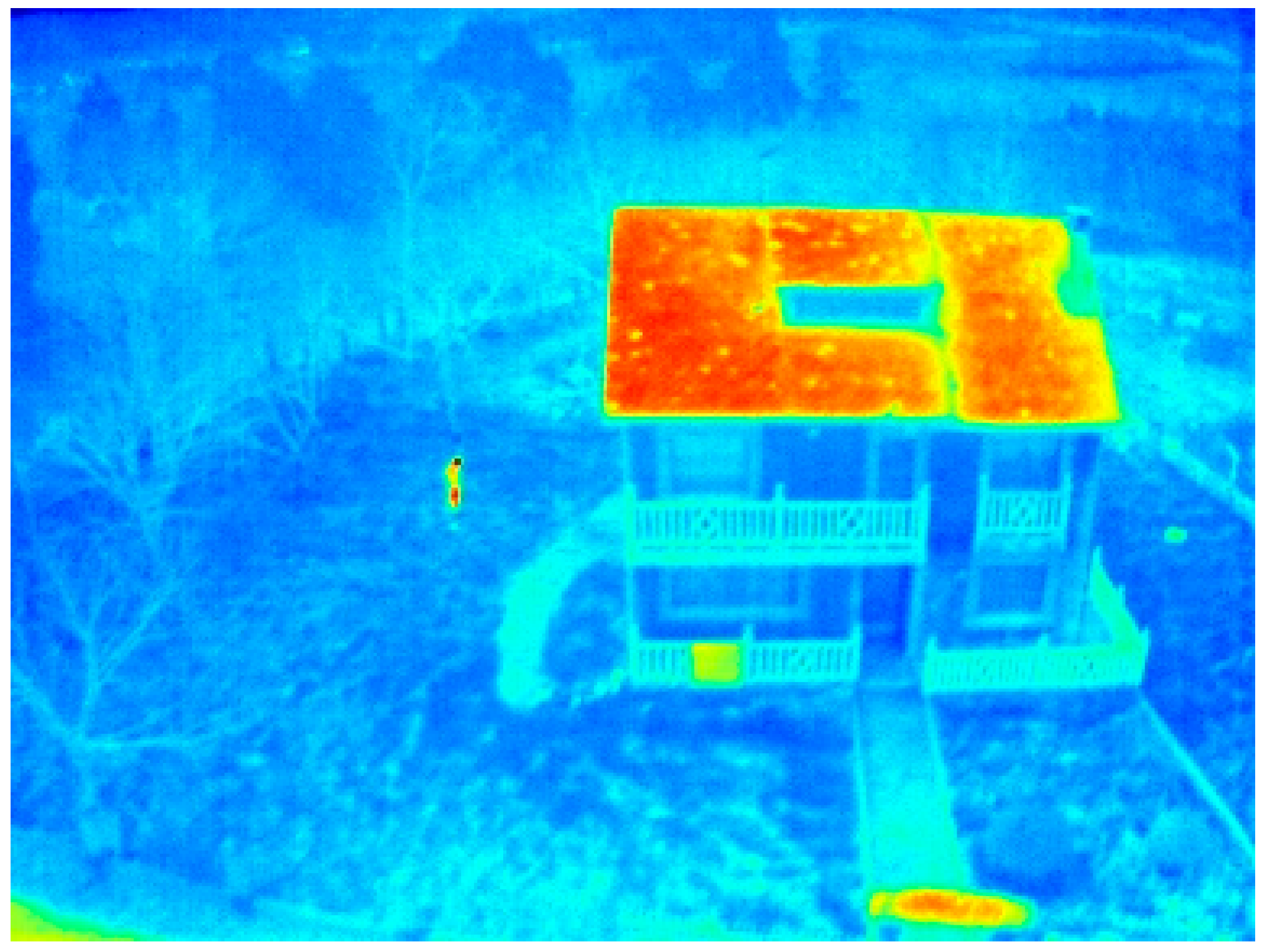
Thermographic inspection from the air can be particularly useful for the monitoring of different industrial facilities. Thermal imaging can be used for the inspection of inaccessible buildings (Figure 10), electric power lines, or photovoltaic systems. It also shows applicability for firefighting and law enforcement.
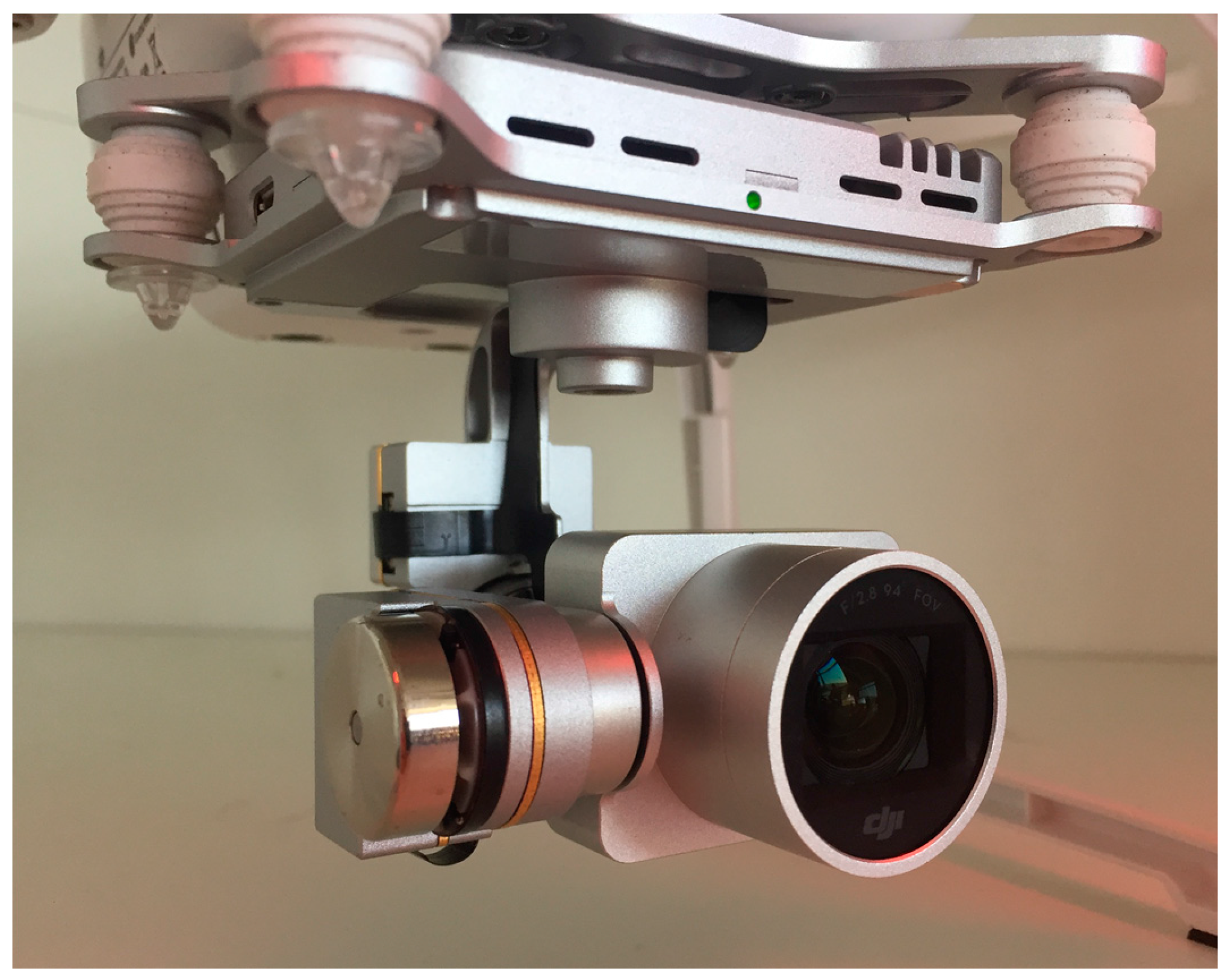
Cameras need to be integrated with platforms using gimbals (Figure 11). They balance the UAS vibration and spurious movements that could induce blurring in images. A gimbal is a motorized platform that uses several sensors, usually accelerometers, a magnetic compass, servos, and a microcontroller, to prevent spurious movement. The most common gimbals are those with two axes that compensate for movement in the roll and pitch angles.
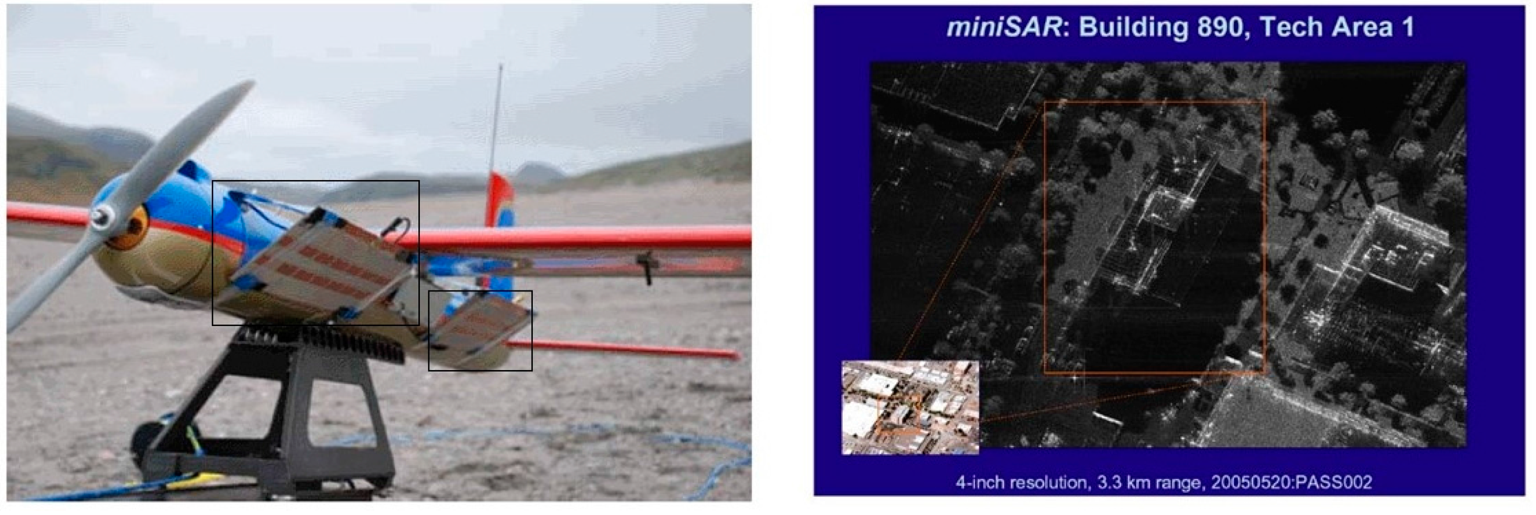
Radio detection and ranging (RADAR) is a remote sensing technology that uses electromagnetic waves for the measurement of distances and velocities. RADAR wavelength operates between 2.7–4.0 mm (W band) and 0.9–6 m (VHF band). Figure 12 shows a micro synthetic aperture RADAR (SAR) mounted on an electric UAS and produces an image. SAR is used to create images of objects. It allows 3D representation and the measurement of terrain deformations with applicability to landslide monitoring [78,79].
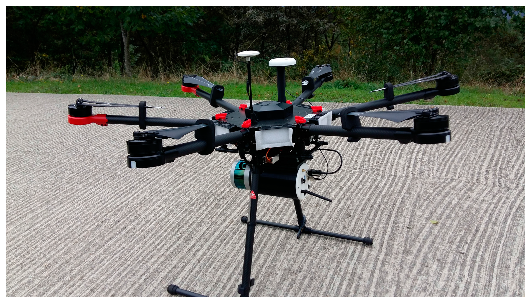
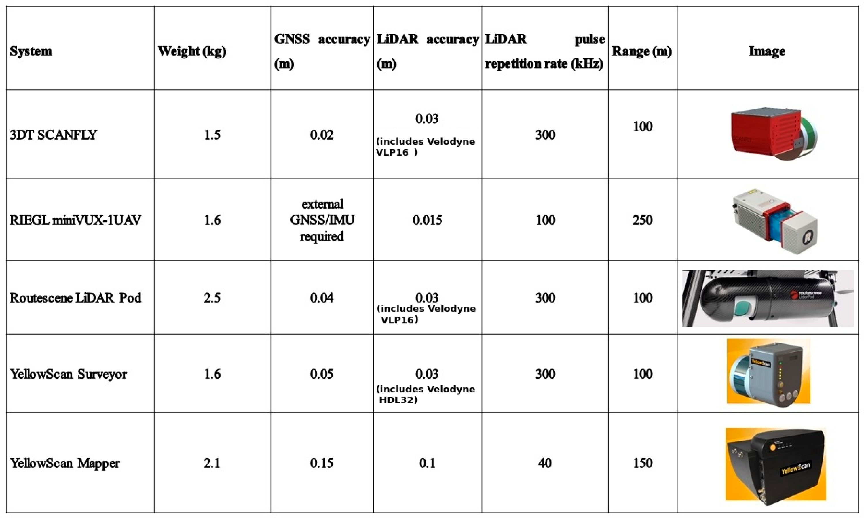
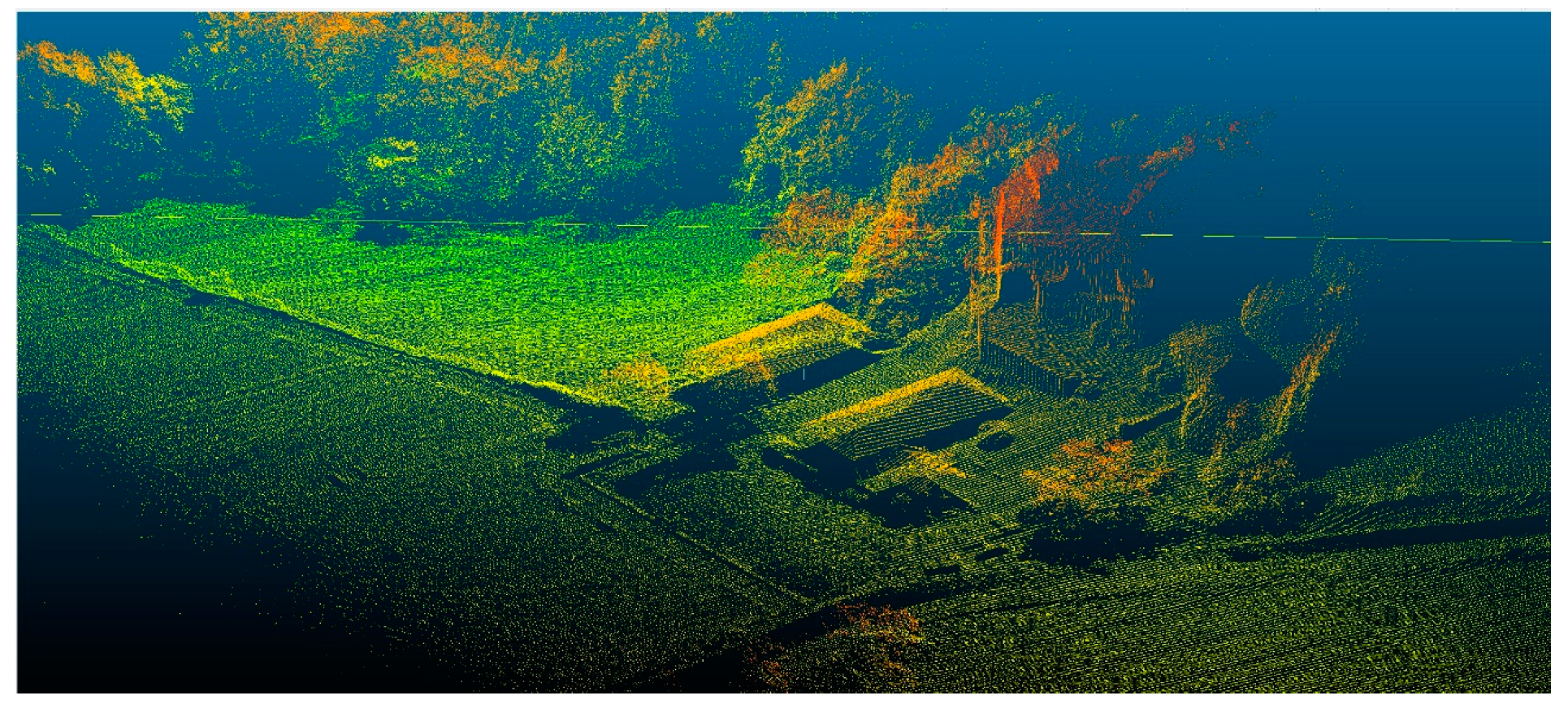
Light detection and ranging (LiDAR) is the other active remote sensing technology linked to UASs. The high geometric accuracy of LiDAR in distance measurements, combined with the declassification of certain high-accuracy INS from military missile guidance systems and miniaturization of electronics and opto-electronics components, contributes to the application of UAS LiDAR technology [80,81]. Figure 13 depicts an example of a Velodyne LiDAR combined with a DJI UAS. Figure 14 shows a number of manufacturers that provide airborne LiDAR solutions for UAS. Figure 15 depicts a point cloud provided by one of the UAS LiDAR systems. The digital geometric information can be seen from the forest and the roofs of the houses. It appears very useful for forest management (i.e., tree height, forest density).
3.6.2. Spraying Systems for Precision Agriculture.
Precision agriculture is a farming management concept based on observing, measuring, and responding to the variability of crop fields. It defines a decision support system for farm management that maximizes outputs and minimizes inputs. Precision agriculture has been improved due to the application of UASs that can be fitted with multispectral and RGB cameras to produce orthoimages of a field and create a normalized difference vegetation index (NDVI) maps. Such maps can provide information about the crop evolution and the requirements for spraying of pesticides and fertilizers. UAS can define an accurate position based on GNSS. This positioning can be used for the accurate application of pesticides and fertilizers, only in the areas where required, according to the remote sensing imaging or field information from Wireless Sensor Networks [87,88,89]. Thus, a UAS mission can be planned based on the field requirements and the use of pesticides and fertilizers can be minimized.
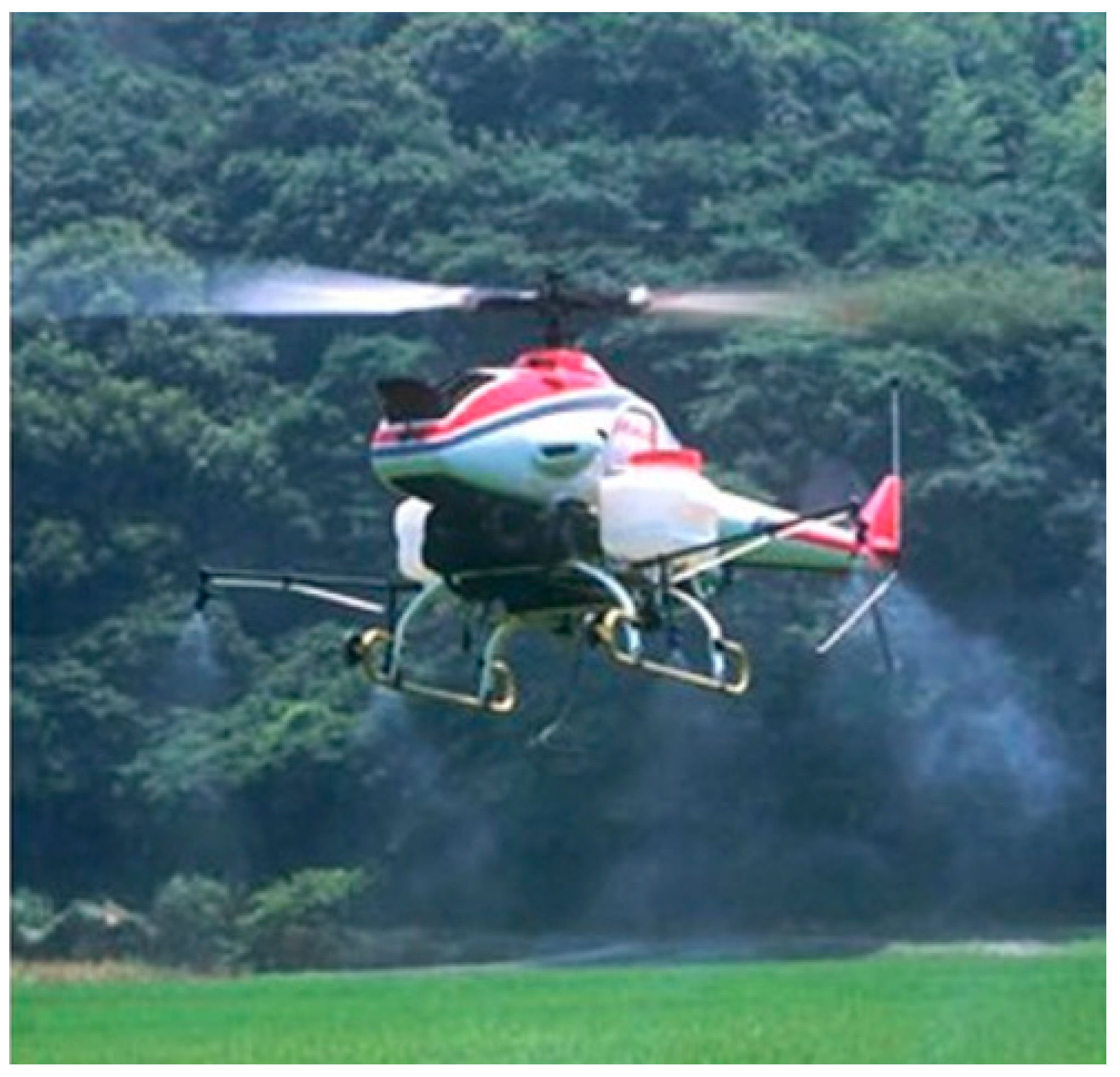
There are a number of commercial applications of spraying drones. Figure 16 shows some examples.
3.6.3. Logistics Systems
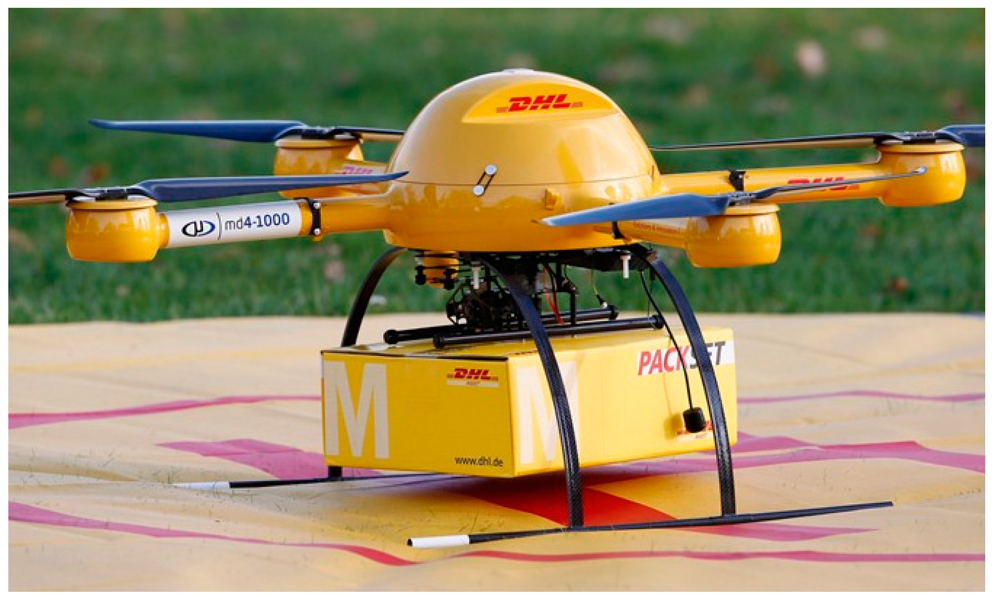
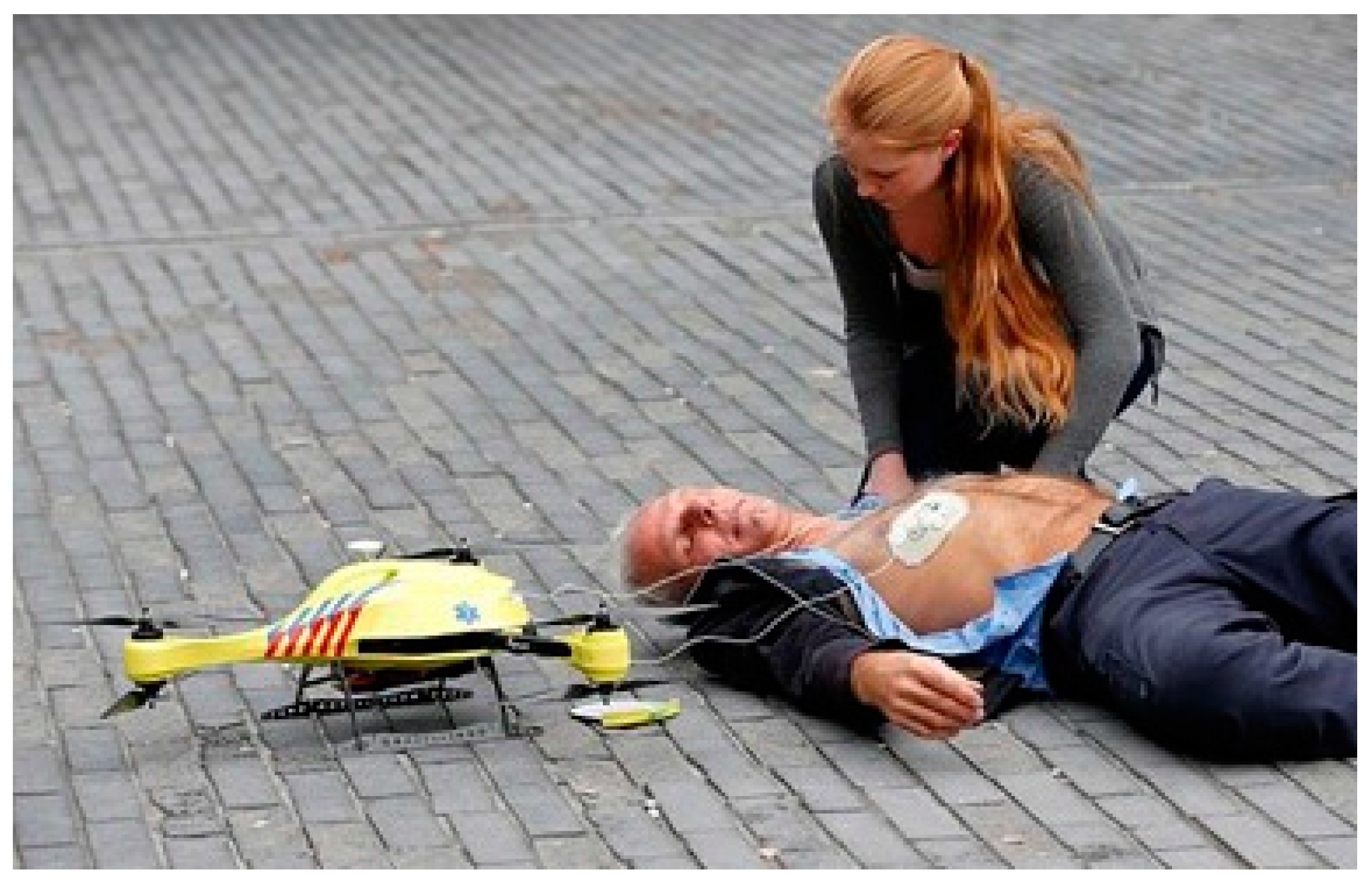
Shipments can arrive from outside the city limits and be stored in hubs or warehouses. They are also classified by size and weight. Then, in the near future, each UAS could automatically pick up the assigned shipment, take off, fly to the delivery point, land, and provide the product to the customer (Figure 17). The potential of UAS technology for logistics is also evident in rural locations with poor infrastructure or isolated populations (e.g., mountains or islands). Medicines or other goods can be provided in a quick manner [93]. Finally, delivery operations related to emergencies are of note: the drone can provide a lifeguard for a castaway, a defibrillator [94] for a person who suffers a heart attack (Figure 18), or a thermal blanket for a mountaineer waiting to be rescued.
4. Regulations
Unmanned aerial systems are a sector of aviation that is fast developing and has great potential for producing new jobs. In the European Union (EU), regulations are developed by the European Aviation Safety Agency (EASA) [95]. These act as prototype regulations that must be adapted by the member states to their national stage. The prototype regulations regulate the operation of UASs within the Single European Sky (SES) airspace [96]. They do not regulate other operations related to the police, the army, or firefighting. The prototype regulations do not introduce changes to the Standardized European Rules of the Air (SERA) [97]. In the EU, the operator of an UAS is responsible for the safe operation of the system and shall comply with the EASA requirements and any other applicable regulations (i.e., security, privacy, data protection, environmental protection, insurance). The UAS operators shall be registered with the competent authority [98]. The UAS shall display identification marks. The competent authorities may designate zones or airspace areas where UAS operations are restricted. The remote pilot responsibilities are of a tactical nature. For example, the pilot should fly the unmanned system within the limitations of the user manual.
UAS are divided into three main categories: open, specific, and certified.
Open category, low risk: It does not require authorization to operate the unmanned aircraft if it avoids restricted areas (i.e., airports, protected areas, or urban areas). Safety is improved through compliance with operational rules, mass limitations (25 kg maximum), and product safety requirements. Insurance is required to cover potential accidents. Flight height is limited to 150 m above ground/sea level and the UAS must remain in the visual line of sight (VLOS). A maximum range of 500 m is allowed. Pilots must be at least 18 years old and pass a remote pilot airman certification. Operation is only allowed during daylight hours. The 25 kg weight limit was chosen because this is a common limit for the “model aircraft” to fly without approval of design. It regulation is typical in most EU countries and it is also a limit adopted by many important partners such as the Federal Aviation Administration (FAA) of the USA [99], the Agência Nacional de Aviação Civil (ANAC) in Brazil [100], or Transport Canada [101]. In addition, some countries such as the USA include more restrictive rules in relation to the maximum ground speed, limited to 161 km/h (100 mph). On the other hand, they allow pilots who are only 16 years old [102]. The requirements to comply with Industry Standards would not be applicable to drone toys of less than 500 g.
Specific category, medium risk: Risk assessment of the specific category is performed by the operator and submitted to the National Aviation Authority (NAA). These are considered medium-risk systems. In the European Union, the NAA is the responsible for the authorization. Standard scenarios are published by EASA, providing an evaluation of the risk of the operation and required risk mitigation measures. The standard scenarios are based on risk assessments for specific types of flights or specific operations (i.e., search and rescue, infrastructure inspections, precision agriculture). The operator should send a declaration to the NAA before the beginning of the mission and the mission must be authorized.
Certified category, higher risk: It shows requirements comparable to those for manned aviation. All procedures are revised by the NAA and include licenses and approval of maintenance, operations, training, risk assessments, etc.
5. Conclusions
The UAS industry has developed rapidly in recent years. The main markets will be maintenance of infrastructure, precision agriculture, surveying, and logistics. Most of the market is occupied by multi-rotor systems, which show higher payload and greater agility than fixed-wing systems. In contrast, fixed-wing systems exhibit greater flight duration.
Remote sensing applications of UAS are fundamental for many of the main markets. They are based on the use of passive sensors such as RGB, multi-spectral, hyper-spectral, and thermal cameras and active sensors such as LiDAR or RADAR. UASs also present an important range of applications in liquid spraying and logistics.
EASA regulations divide the operations into three categories: open, specific, and certified, depending on the characteristics of the missions and the aircraft type.
Future trends in UAS technology will be focused on the following aspects: increasing the flight time; establishing a stable regulatory framework; integrating sense and avoid systems, parachute systems, and shock absorber systems to increase safety; developing robust indoor navigation in scenarios without GNSS coverage; improving control systems under active payloads (i.e., fluid spraying, robotics arms); developing robust integration with manned aircraft applications; improving the possibility of performing collaborative work with other autonomous systems (ground, marine, and aerial); and improving UAS-human interaction.
Acknowledgments
The authors would like to thank the Spanish government (Grant No.: TIN2016-77158-C4-1-R) and Xunta de Galicia (Exp No.: ED431C 2016-038).
Author Contributions
H. González-Jorge developed the abstract, introduction, UAV classification, and conclusions. J. Martínez-Sánchez focused his work on UAV subsystems (frame, propellers, motors, batteries, and autopilot). M. Bueno developed the subsystems part related to payloads and data processing. P. Arias wrote the regulations part.
Conflicts of Interest
The authors declare no conflict of interest.
References
- Chiesa, S.; Fioriti, M.; Fusaro, R. Male UAV and its systems as a basis of future definitions. Aircr. Eng. Aerosp. Technol. 2016, 88, 771–782. [Google Scholar] [CrossRef]
- Dow, J.M.; Neilan, R.E. The international GNSS service in a changing landscape of Global Navigation Satellite Systems. J. Geod. 2009, 83, 191–198. [Google Scholar] [CrossRef]
- Ge, M.; Gendt, G.; Rothacher, M.; Shi, C.; Liu, J. Resolution of GPS carrier-phase ambiguities in Precise Point Positioning (PPP) with daily observations. J. Geod. 2008, 82, 389–399. [Google Scholar] [CrossRef]
- Dow, J.M.; Neilan, R.E.; Gendt, G. The international GPS service: Celebrating the 10th anniversary and looking to the next decade. Adv. Space Res. 2005, 36, 320–326. [Google Scholar] [CrossRef]
- Sukkarieh, S.; Nebot, E.M.; Durrant-Whyte, H.F. A high integrity IMU/GPS navigation loop for autonomous land vehicle applications. IEEE Trans. Robot. Autom. 1999, 15, 572–578. [Google Scholar] [CrossRef]
- Mirzaei, F.M.; Roumeliotis, S.I. A Kalman filter-based algorithm for IMU-camera calibration: Observability analysis and performance evaluation. IEEE Trans. Robot. 2008, 24, 1143–1156. [Google Scholar] [CrossRef]
- Wendel, J.; Meister, O.; Schlaile, C.; Trommer, G.F. An integrated GPS/MEMS-IMU navigation system for an autonomous helicopter. Aerosp. Sci. Technol. 2006, 10, 527–533. [Google Scholar] [CrossRef]
- Feliz, R.; Zalama, E.; García-Bermejo, J.G. Pedestrian tracking using inertial sensors. J. Phys. Agents 2009, 3, 35–42. [Google Scholar]
- Herissé, B.; Hamel, T.; Mahony, R.; Russotto, F.X. Landing a VTOL unmanned aerial vehicle on a moving platform using optical flown. IEEE Trans. Robot. 2012, 28, 77–89. [Google Scholar] [CrossRef]
- Filgueira, A.; González-Jorge, H.; Lagüela, S.; Díaz-Vilariño, L.; Arias, P. Quantifying the influence of rain in LiDAR performance. Measurement 2017, 95, 143–148. [Google Scholar] [CrossRef]
- Hyyppä, J.; Hyyppä, H.; Leckie, D.; Gougeon, F.; Yu, X.; Maltamo, M. Review of methods of small-footprint airborne laser scanning for extracting forest inventory data in boreal forests. Int. J. Remote Sens. 2008, 29, 1339–1366. [Google Scholar] [CrossRef]
- Leberl, F.; Irschara, A.; Pock, T.; Meixner, P.; Gruber, M.; Scholz, S.; Wiechert, A. Point clouds: LiDAR versus 3D vision. Photogramm. Eng. Remote Sens. 2010, 76, 1123–1134. [Google Scholar] [CrossRef]
- Chan, Y.K.; Koo, V.C. An introduction to synthetic aperture radar (SAR). Prog. Electromagn. Res. B 2008, 3, 27–60. [Google Scholar] [CrossRef]
- Ulander, L.M.H.; Hellsten, H.; Stenstrom, G. Synthetic-aperture radar processing using fast factorized back-projection. IEEE Trans. Aerosp. Electron. Syst. 2003, 39, 760–776. [Google Scholar] [CrossRef]
- Meng, P.; Wu, J.; Schwager, K.L.; Zhao, F.; Dennison, P.E.; Cook, B.C.; Brewster, K.; Green, T.M.; Serbin, S.P. Using high spatial resolution satellite imagery to map forest burn severity across spatial scales in a Pine Barrens ecosystem. Remote Sens. Environ. 2017, 191, 95–109. [Google Scholar] [CrossRef]
- Luo, X.; Wang, M.; Dai, G.; Song, Z. Constellation design for earth observation based on the characteristics of the satellite ground track. Adv. Space Res. 2017, 59, 1740–1750. [Google Scholar] [CrossRef]
- Brekke, C.; Solberg, A.H.S. Oil spill detection by satellite remote sensing. Remote Sens. Environ. 2005, 95, 1–13. [Google Scholar] [CrossRef]
- Ozesmi, S.L.; Bauer, M.E. Satellite remote sensing of wetlands. Wetl. Ecol. Manag. 2002, 10, 381–402. [Google Scholar] [CrossRef]
- Scarpa, F. Unmanned aerial vehicles. In Aircraft Engineering and Aerospace Technology; Emerald Group Publishing Limited: Bingley, UK, 2001; Volume 73. [Google Scholar]
- Everaerts, J. The use of unmanned aerial vehicles (UAVs) for remote sensing and mapping. Int. Arch. Photogramm. Remote Sens. Spat. Inf. Sci. 2008, 37, 1187–1192. [Google Scholar]
- Gupte, S.; Mohandas, P.I.T.; Conrad, J.M. A survey of quadrotor unmanned aerial vehicles. In Proceedings of the IEEE Southeaston, Orlando, FL, USA, 15–18 March 2012; pp. 1–6. [Google Scholar]
- Ollero, A.; Merino, L. Control and perception techniques for aerial robotics. Annu. Rev. Control. 2004, 28, 167–178. [Google Scholar] [CrossRef]
- Szantoi, Z.; Smith, S.E.; Strona, G.; Koh, L.P.; Wich, S.A. Mapping orangutan habitat and agricultural areas using Landsat OLI imagery augmented with unmanned aircraft system aerial photography. Int. J. Remote Sens. 2017, 38, 2231–2245. [Google Scholar] [CrossRef]
- Blon, J.D. Unmanned Aerial Systems: A Historical Perspective; Combat Studies Institute Press: Fort Leavenworth, KS, USA, 2010; Available online: http://usacac.army.mil/cac2/cgsc/carl/download/csipubs/OP37.pdf (accessed on 1 February 2017).
- Keane, J.F.; Carr, S.S. A brief history of early unmanned aircraft. Johns Hopkins APL Tech. Dig. 2013, 32, 558–571. Available online: http://www.jhuapl.edu/techdigest/TD/td3203/32_03-Keane.pdf (accessed on 1 February 2017).
- Microdrones. Available online: https://www.microdrones.com/en/team/our-story/ (accessed on 1 February 2017).
- Parrot Sensefly eBee. Available online: https://www.sensefly.com/drones/ebee.html (accessed on 1 February 2017).
- Drone Classification. Available online: http://www.rohde-schwarz-usa.com/rs/324-UVH-477/images/Drone_Monitoring_Whitepaper.pdf (accessed on 1 February 2017).
- Dalamagkidis, K. Classification of UAVs. In Handbook of Unmanned Aerial Vehicles; Springer: Houten, The Netherlands, 2014; pp. 83–91. [Google Scholar]
- Watts, A.C.; Ambrosia, V.G.; Hinkley, E.A. Unmanned aircraft systems in remote sensing and scientific research: Classification and considerations of use. Remote Sens. 2012, 4, 1671–1692. [Google Scholar] [CrossRef]
- DJI Inspire 2. Available online: http://www.dji.com/es/inspire-2 (accessed on 1 February 2017).
- DJI Phantom 4. Available online: https://www.dji.com/es/phantom-4 (accessed on 1 February 2017).
- DJI S1000. Available online: http://www.dji.com/es/spreading-wings-s1000-plus (accessed on 1 February 2017).
- Mikrokopter Okto XL. Available online: http://wiki.mikrokopter.de/en/MK-OktoXL (accessed on 1 February 2017).
- UAV Instruments Ons 2500. Available online: http://www.uav-instruments.com/ons-2500/ (accessed on 1 February 2017).
- UAV Instruments Cies 2000. Available online: http://www.uav-instruments.com/cies-2000/ (accessed on 1 February 2017).
- Erle-Copter. Available online: http://erlerobotics.com/blog/erle-copter/ (accessed on 1 February 2017).
- Aibotix X6. Available online: https://www.aibotix.com/ (accessed on 1 February 2017).
- Riegl Ricopter. Available online: http://riegl.com/products/unmanned-scanning/riegl-ricopter (accessed on 1 February 2017).
- 3DR Solo Drone. Available online: https://3dr.com/solo-drone/ (accessed on 1 February 2017).
- Walkera QT X800. Available online: http://www.walkeraonline.com/walkera-qr-x800-gps-quadcopter.html (accessed on 1 February 2017).
- Elimco E300. Available online: http://www.elimco.com/eng/p_UAV-E300_24.html (accessed on 1 February 2017).
- Drone Dynamics Sky Eye. Available online: http://www.dronedynamics.com/skyeye-sentinel-x4/ (accessed on 1 February 2017).
- AscTec Falcon 8. Available online: http://www.asctec.de/en/asctec-professional-uav/intel-falcon-8-plus/ (accessed on 1 February 2017).
- MMC F6. Available online: http://en.mmcuav.com/ProductsSt/197.html (accessed on 1 February 2017).
- MMC A6 Plus. Available online: http://en.mmcuav.com/ProductsSt/199.html (accessed on 1 February 2017).
- Microdrones MD4 3000. Available online: https://www.microdrones.com/en/products/md4-3000/ (accessed on 1 February 2017).
- Microdrones MD4 1000. Available online: https://www.microdrones.com/en/mdsolutions/mdmapper1000dg/ (accessed on 1 February 2017).
- Microdrones MD4 200. Available online: https://www.microdrones.com/en/mdsolutions/mdmapper200/ (accessed on 1 February 2017).
- Quaternium Spidex Pro. Available online: http://www.quaternium.com/portfolio/spidex-pro-uav/ (accessed on 1 February 2017).
- Quaternium Hybrix. Available online: http://www.quaternium.com/portfolio/hybrix-uav/ (accessed on 1 February 2017).
- Kumar, V.; Michael, N. Opportunities and challenges with autonomous micro aerial vehicles. Robot. Res. 2016, 100, 41–58. [Google Scholar]
- Tripolitsotis, A.; Prokas, N.; Kyritsis, S.; Dollas, A.; Papaefstathiou, I.; Partsinevelos, P. Dronesourcing: A modular, expandable multi-sensor UAV platform for combined, real-time environmental monitoring. Int. J. Remote Sens. 2017, 38, 2757–2770. [Google Scholar] [CrossRef]
- Anemaat, W.A.J.; Schuurman, M.; Liu, W.; Karwas, A. Aerodynamic design, analysis and testing of propellers for small unmanned aerial vehicles. In Proceedings of the 55th AIAA Aerospace Sciences Meeting, Grapevine, TX, USA, 7–10 January 2017. [Google Scholar]
- Patel, Y.; Gaurav, A.; Srinivas, K.; Singh, Y. A review on design and analysis of the propeller used in UAV. Int. J. Adv. Prod. Ind. Eng. 2017, 605, 20–23. [Google Scholar]
- Lizuka, K.; Uzuhashi, H.; Kano, M. Microcomputer control for sensorless brushless motor. IEEE Trans. Ind. Appl. 1985, IA-21, 595–601. [Google Scholar]
- Shen, J.X.; Iwasaki, S. Sensorless control of ultrahigh-speed PM brushless motor using PLL and third harmonic back EMF. IEEE Trans. Ind. Appl. 2006, 53, 421–428. [Google Scholar] [CrossRef]
- Dudek, M.; Tomczyk, P.; Wygonik, P.; Korkosz, M.; Bogusz, P.; Lis, B. Hybrid fuel cell–battery system as a main power unit for small unmanned aerial vehicles (UAV). Int. J. Electrochem. Sci. 2013, 8, 8442–8463. [Google Scholar]
- Shiau, J.K.; Ma, D.M.; Yang, P.Y.; Wang, G.F.; Gong, J.H. Design of solar power management system for an experimental UAV. IEEE Trans. Aerosp. Electron. Syst. 2009, 45, 11071094. [Google Scholar] [CrossRef]
- Abdilla, A.; Richards, A.; Burrow, S. Power and endurance modelling of battery-powered rotorcraft. In Proceedings of the IEEE/RSJ International Conference on Intelligent Robots and Systems (IROS), Hamburg, Germany, 28 September–2 October 2015. [Google Scholar]
- Criado, R.M.; Rubio, F. Autonomous path tracking control design for a commercial quadcopter. IFAC Workshop Adv. Control Navig. Auton. Aerosp. Veh. 2015, 48, 73–78. [Google Scholar]
- Lienard, J.; Vogs, A.; Gatziolis, D.; Strigul, N. Embedded, real-time UAV control for improved, image based 3D scene reconstruction. Measurement 2016, 81, 264–269. [Google Scholar] [CrossRef]
- Varga, M.; Zufferey, J.C.; Heitz, G M.H.M.; Floreano, D. Evaluation of control strategies for fixed-wing drones following slow-moving ground agents. Robot. Auton. Syst. 2015, 72, 285–294. [Google Scholar] [CrossRef]
- Pixhawk Autopilot. Available online: http://www.pixhawk.org/ (accessed on 1 February 2017).
- Pixhawk 2 Autopilot. Available online: http://www.proficnc.com/ (accessed on 1 February 2017).
- Pixracer Autopilot. Available online: http://px4.io/docs/pixracer/ (accessed on 1 February 2017).
- Navio + Autopilot. Available online: https://emlid.com/navio-plus/ (accessed on 1 February 2017).
- Navio 2 Autopilot. Available online: https://emlid.com/shop/navio2/ (accessed on 1 February 2017).
- Parrot Bebop Autopilot. Available online: http://ardupilot.org/copter/docs/parrot-bebop-autopilot.html (accessed on 1 February 2017).
- Intel Aero Autopilot. Available online: http://ardupilot.org/copter/docs/common-intel-aero-overview.html (accessed on 1 February 2017).
- Qualcomm Snapdragon Flight Kit. Available online: http://ardupilot.org/copter/docs/common-qualcomm-snapdragon-flight-kit.html (accessed on 1 February 2017).
- Zongjian, L. UAV for mapping—Low altitude photogrammetric survey. Int. Arch. Photogramm. Remote Sens. Spat. Inf. Sci. 2008, 37, 1183–1186. [Google Scholar]
- Xiang, H.; Tian, L. Method for automatic georeferencing aerial remote sensing (RS) images from an unmanned aerial vehicle (UAV) platform. Biosyst. Eng. 2011, 108, 104–113. [Google Scholar] [CrossRef]
- Niethammer, U.; Rothmund, S.; James, M.R.; Travelletti, J.; Joswig, M. UAV-based remote sensing of landslides. Int. Arch. Photogramm. Remote Sens. Spat. Inf. Sci. 2010, 38, 496–501. [Google Scholar]
- Wallace, L.; Lucieer, A.; Watson, C.; Turner, D. Development of a UAV-LiDAR system with application to forest inventory. Remote Sens. 2012, 4, 1519–1543. [Google Scholar] [CrossRef]
- Bendea, H.; Boccardo, P.; Dequal, S.; Giulio Tonolo, F.; Marenchino, D.; Piras, M. Low cost UAV for post-disaster assessment. Int. Arch. Photogramm. Remote Sens. Spat. Inf. Sci. 2008, 37, 1373–1380. [Google Scholar]
- Smith, S.; Szantoi, Z.; Perry, J.; Percival, F.; Evers, B. Design considerations for remote sensing payloads on inexpensive unmanned autonomous aerial vehicles. Surv. Land Inf. Sci. 2010, 70, 131–137. [Google Scholar]
- Xing, M.; Jiang, X.; Wu, R.; Zhou, F.; Bao, Z. Motion compensation for UAV SAR based on raw radar data. IEEE Trans. Geosci. 2009, 47, 2870–2883. [Google Scholar] [CrossRef]
- Essen, H.; Johannes, W.; Stanko, S.; Sommer, R.; Wahlen, A.; Wilcke, J. High resolution W-band UAV SAR. In Proceedings of the IEEE International Geoscience and Remote Sensing, Munich, Germany, 22–27 July 2012. [Google Scholar]
- Wallace, L. Assessing the stability of canopy maps produced from UAV-LiDAR data. In Proceedings of the IEEE International Geoscience and Remote Sensing Symposium, Melbourne, Australia, 21–26 July 2013. [Google Scholar]
- Salamí, E.; Barrad, C.; Pastor, E. UAV flight experiments applied to the remote sensing of vegetated áreas. Remote Sens. 2014, 6, 11051–11081. [Google Scholar] [CrossRef]
- 3DT Scanfly. Available online: http://www.3dtarget.it/eu/en/uav/uav-products/lidar/velodyne-vlp-16-puck-848-1632-2050-detail.html (accessed on 1 February 2017).
- Riegl MiniVUX-1UAV. Available online: http://www.riegl.com/products/unmanned-scanning/new-riegl-minivux-1uav/ (accessed on 1 February 2017).
- Routescene LiDAR Pod. Available online: http://www.routescene.com/products/product/uav-lidarpod/ (accessed on 1 February 2017).
- YellowScan Surveyor. Available online: http://www.yellowscan.fr/products/yellowscan-surveyor (accessed on 1 February 2017).
- YellowScan Mapper. Available online: http://www.yellowscan.fr/products/yellowscan-mapper (accessed on 1 February 2017).
- Faical, B.; Costa, F.G.; Pessin, G.; Ueyama, J.; Freitas, H.; Colombo, A.; Fini, P.H.; Villas, L.; Osório, F.S.; Vargas, P.A.; et al. The use of unmanned aerial vehicles and wireless sensor networks for spraying pesticides. J. Syst. Arch. 2014, 60, 393–404. [Google Scholar] [CrossRef]
- Pederi, Y.A.; Cheporniuk, H.S. Unmanned aerial vehicles and new technological methods of monitoring and crop protection in precision agriculture. Actual problems of unmanned aerial vehicles developments. In Proceedings of the IEEE International Conference Actual Problems of Unmanned Aerial Vehicles Developments (APUAVD), Kiev, Ukraine, 13–15 October 2015. [Google Scholar]
- Ehmke, T. Unmanned aerial systems for field scouting and spraying. Crops Soils 2013, 46, 4–9. [Google Scholar] [CrossRef]
- Mckinnon, A.C. The possible impact of 3D printing and drones on last-mile logistics: An exploratory study. Built Environ. 2016, 42, 617–629. [Google Scholar] [CrossRef]
- Cordova, F.; Olivares, V. Design of drone fleet management model in a production system of customized products. In Proceedings of the 6th International Conference on Computers Communications and Control, Oradea, Romania, 10–14 May 2016. [Google Scholar]
- Tavana, M.; Khalili-Damghani, K.; Santos-Arteaga, F.J.; Zandi, M.H. Drone shipping versus truck delivery in a cross-docking system with multiple fletes and products. Expert Syst. Appl. 2017, 72, 93–107. [Google Scholar] [CrossRef]
- DHL Drone Logistics. Available online: http://www.dhl.com/content/dam/downloads/g0/about_us/logistics_insights/DHL_TrendReport_UAV.pdf (accessed on 1 February 2017).
- Ambulance Drone. Available online: https://www.tudelft.nl/en/ide/research/research-labs/applied-labs/ambulance-drone/ (accessed on 1 February 2017).
- EASA. Available online: https://www.easa.europa.eu/ (accessed on 1 February 2017).
- Single European Sky. Available online: http://www.eurocontrol.int/dossiers/single-european-sky (accessed on 1 February 2017).
- Standardized European Rules of the Air. Available online: https://www.eurocontrol.int/sites/default/files/article/content/documents/single-sky/mandates/20090814-sera-parta-ec-mandate.pdf (accessed on 1 February 2017).
- Aviation Authorities. Available online: https://en.wikipedia.org/wiki/List_of_civil_aviation_authorities (accessed on 1 February 2017).
- Federal Aviation Administration. Available online: www.faa.gov (accessed on 1 February 2017).
- Agência Nacional de Aviação Civil. Available online: www.anac.gov.br (accessed on 1 February 2017).
- Transport Canada. Available online: www.tc.gc.ca/eng/civilaviation/menu.htm (accessed on 1 February 2017).
- USA Regulation for UAS. Available online: https://www.faa.gov/uas/ (accessed on 1 February 2017).
Figure 1.
Hewitt-Sperry Automatic Airplane (image source: Wikipedia).
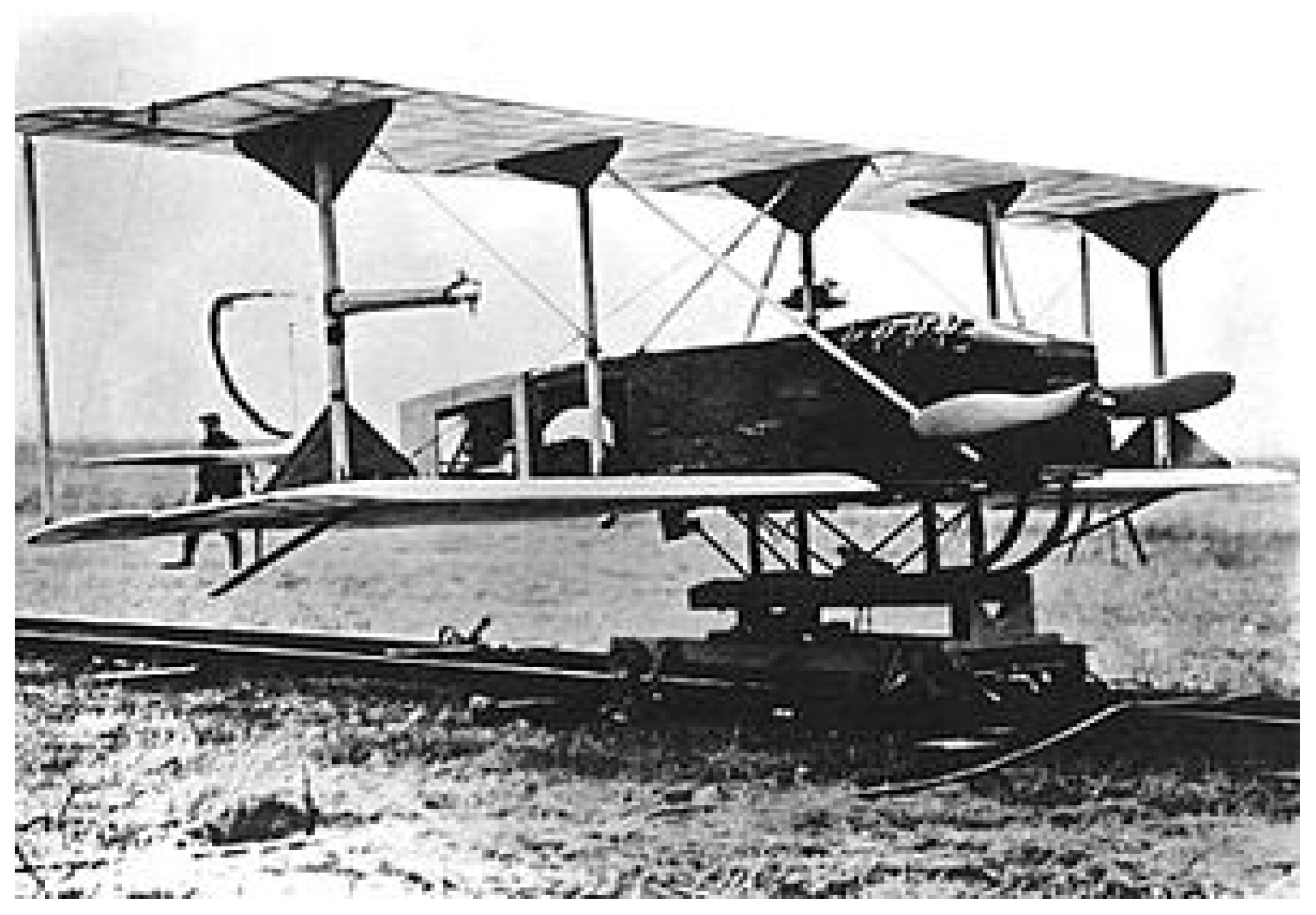
Figure 2.
Fixed-wing UAS (image source: authors).

Figure 3.
Rotary-wing UAS (image source: authors).

Figure 4.
Example of carbon fiber and plastic propellers (image source: Wikipedia).

Figure 5.
Examples of brushless motors (image source: authors).
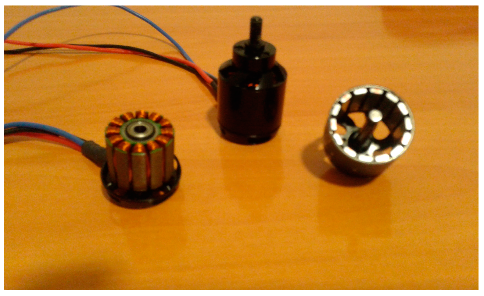
Figure 6.
Example of ESC (left) and PWM (right) (image source: authors).

Figure 7.
Autopilot interconnection with sensing and actuating subsystems (image source: authors).

Figure 8.
Waypoints definition using QGroundControl (image source: authors).
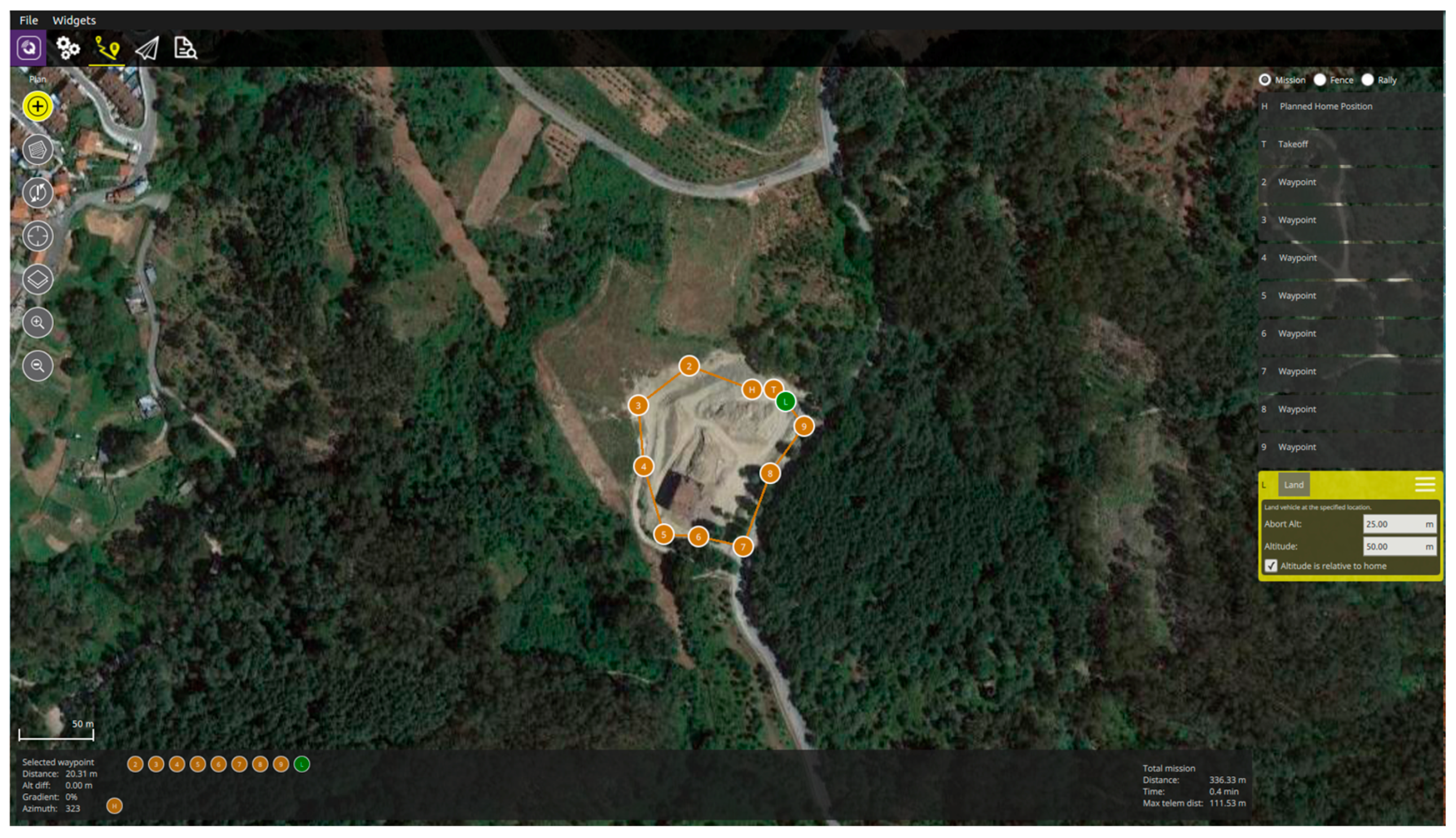
Figure 9.
Inspection operation of power lines using a Microdrones quadrotor (top) and imaging results (bottom) (image source: Wikipedia).
Figure 9.
Inspection operation of power lines using a Microdrones quadrotor (top) and imaging results (bottom) (image source: Wikipedia).

Figure 10.
Thermal inspection to evaluate energy efficiency (image source: authors).

Figure 11.
Gimbal from DJI Phantom 3 UAS (image source: authors).

Figure 12.
SAR (inside black rectangles) mounted on a UAS (left) and SAR image (right) (image source: Wikipedia).
Figure 12.
SAR (inside black rectangles) mounted on a UAS (left) and SAR image (right) (image source: Wikipedia).

Figure 13.
Velodyne VLP16 LiDAR integrated in a DJI Matrice 600 UAS system (image source: authors).

Figure 14.
Technical specifications of different airborne LiDAR for UAS (image source: authors). The weights are below many UAS typical payloads [82,83,84,85,86], although they are specially indicated for rotary-wing UAS due to the higher payload capability.

Figure 15.
Point cloud obtained from DJI Matrice 600 UAS and Velodyne LiDAR VLP16 (image source: authors).
Figure 15.
Point cloud obtained from DJI Matrice 600 UAS and Velodyne LiDAR VLP16 (image source: authors).

Figure 16.
Spraying drone Yamaha Rmax with two tanks of 8 L each (image source: Wikipedia).

Figure 17.
DHL logistic system (image source: DHL).

Figure 18.
Emergency applications. Drone defibrillator (image source: TUDelft).


| Autopilot | Processor | Sensors | Interfaces |
|---|---|---|---|
| Pixhawk Weight 38 g Size 50 × 81.5 mm | 32-bit ARM Cortex M4 core with FPU 168 Mhz/256 KB RAM/2 MB Flash. 32-bit failsafe co-processor. | MPU6000 as main accel and gyro. ST Micro 16-bit gyroscope. ST Micro 14-bit accelerometer/compass (magnetometer). MEAS barometer. | 5x UART serial ports, 1 high-power capable, 2 with HW flow control Spektrum DSM/DSM2/DSM-X Satellite input. Futaba S.BUS input (output not yet implemented). PPM sum signal. RSSI (PWM or voltage) input. I2C, SPI, 2x CAN, USB. 3.3 V and 6.6 V ADC inputs. |
| Pixhawk2 (TheCube) | 32-bit ARM. Cortex M4 core with FPU. 168 Mhz/256 KB RAM/2 MB Flash. 32-bit failsafe co-processor. | Three redundant IMUs (accels, gyros and compass). InvenSense MPU9250, ICM20948 and/or ICM20648 as first and third IMU (accel and gyro). ST Micro L3GD20 + LSM303D or InvenSense ICM2076xx as backup IMU (accel and gyro). Two redundant MS5611 barometers. | 14x PWM servo outputs (8 from IO, 6 from FMU). S.Bus servo output. R/C inputs for CPPM, Spektrum/DSM and S.Bus. Analogue/PWM RSSI input. 5x general purpose serial ports, 2 with full flow control. 2x I2C ports. SPI port (un-buffered, for short cables only not recommended for use). 2x CAN Bus interface. 3x Analogue inputs (3.3 V and 6.6 V). High-powered piezo buzzer driver (on expansion board). High-power RGB LED (I2C driver compatible connected externally only). Safety switch/LED. Optional carrier board for Intel Edison. |
| Pixracer Weight— Size 36 × 36 mm | MCU—STM32F427VIT6 rev.3. Ultra low noise LDOs for sensors and FMU FRAM—FM25V02-G | Gyro/Accelerometer: Invensense MPU9250 Accel/Gyro/Mag (4 KHz). Gyro/Accelerometer: Invensense ICM-20608 Accel/Gyro (4 KHz). Barometer: MS5611. Compass: Honeywell HMC5983 magnetometer with temperature compensation. | Wifi: ESP-01 802.11bgn Flashed with MavESP8266. MicroSD card reader. Micro USB. RGB LED. GPS (serial + I2C). TELEM1/TELEM2. Wifi serial. FrSky Telemetry serial. Dronecode Debug connector (serial + SWD). Connectors: GPS + I2C, RC-IN, PPM-IN, RSSI, SBus-IN, Spektrum-IN, USART3 (TxD, RxD, CTS, RTS), USART2 (TxD, RxD, CTS, RTS), FRSky-IN, FRSky-OUT, CAN, USART8 (TxD, RxD), ESP8266 (full set), SERVO1-SERVO6, USART7 (TxD, RxD), JTAG (SWDIO, SWCLK), POWER-BRICK (VDD, Voltage, Current, GND), BUZZER-LED_BUTTON. |
| Autopilot | Processor | Sensors | Interfaces |
|---|---|---|---|
| Navio+ Weight 12 g (shield) + 54 g (RPi2) Size 55 × 65 mm (shield only) | Raspberry PI 2 900 Mhz quad-core ARM Cortext-A7 CPU 1 GB RAM. | MPU9250 as main accel, gyro and compass. MS5611 barometer. U-Blox M8N GPS. | UART, SPI, I2C. PWM Sum input. Futaba S.BUS input. 13 PWM servo outputs. |
| Navio 2 Weight 23 g (shield) + 54 g (RPi2) Size 55 × 65 mm (shield only) | Raspberry PI 3 1.2 GHz 64-bit quad-core ARMv8 CPU 1 GB RAM | MPU9250 9DOF IMU. LSM9DS1 9DOF IMU. MS5611 Barometer. U-blox M8N. Glonass/GPS/Beidou. RC I/O co-processor. | UART, I2C, ADC for extensions. PWM/S.Bus input. 14 PWM servo outputs. |
| Parrot Bebop Weight 400 g (with hull) Size 33 × 38 mm | Parrot P7 dual-core CPU Cortex 9 with quad core GPU 8 GB flash | MPU6050 for accelerometers and gyroscope (I2C). AKM 8963 compass. MS5607 barometer. Furuno GN-87F GPS. Sonar. Optical-flow. HD camera. | 1x UART serial ports. USB. Built-in Wifi. |
| Intel Aero Weight 30 g (without heatsink), 60 g (with heatsink) Size 88 × 63 mm | Intel® Atom™ x7-Z8700. Processor—2.4 GHz burst, quad core, 2 M cache, 64 bit 4 GB RAM LPDDR3-1600—32 GB eMMC | Bosch BMI160 6-Axis IMU. Bosch BMC150 6-axis compass. MS5611 Barometer. | I2C × 2. UART. SPI. CAN. 5 analog inputs. 25 programmable GPIO pins. Wi-Fi (802.11ac). 1 micro HDMI 1.4b. 1 USB 3.0 On-the-Go (OTG) connector. MIPI (CSI-2) 4-lanes + 1 lane connector. microSD memory card slot. M.2 connector 1 lane PCIe for SSD. |
| Qualcomm Snapdragon Flight Kit Weight- Size 68 × 52 mm | CPU: Quad-core 2.26 GHz Krait. DSP: Hexagon DSP (QDSP6 V5A)—801 MHz + 256KL2 (running the flight code). GPU: Qualcomm® Adreno™ 330 GPU. RAM: 2 GB LPDDR3 PoP @931 MHz. Storage: 32 GB eMMC Flash. | MPU: Invensense MPU-9250 9-Axis Sensor, 3 × 3 mm QFN. Barometer: Bosch BMP280 barometric pressure sensor. Optical Flow: Omnivision OV7251 on Sunny Module MD102A-200 Video: Sony IMX135 on Liteon Module 12P1BAD11 (4k@30fps 3840 × 2160 video capture to SD card with H.264 @ 100 Mbits (1080p/60 with parallel FPV), 720p FPV). GPS: Telit Jupiter SE868 V2 module. | Wifi: Qualcomm® VIVE™ 1-stream 802.11n/ac with MU-MIMO Integrated digital core. BT/WiFi: BT 4.0 and 2 G/5 G WiFi via QCA6234. 802.11n, 2 × 2 MIMO with 2 uCOAX connectors on-board for connection to external antenna. uCOAX connector on-board for connection to external GPS patch antenna. CSR SiRFstarV @ 5 Hz via UART One USB 3.0 OTG port (micro-A/B) Micro SD card slot. Gimbal connector (PWB/GND/BLSP). ESC connector (2W UART). I2C. 60-pin high speed Samtec QSH-030-01-L-D-A-K expansion connector. 2x BLSP (BAM Low Speed Peripheral). |
© 2017 by the authors. Licensee MDPI, Basel, Switzerland. This article is an open access article distributed under the terms and conditions of the Creative Commons Attribution (CC BY) license (http://creativecommons.org/licenses/by/4.0/).
Share and Cite
MDPI and ACS Style
González-Jorge, H.; Martínez-Sánchez, J.; Bueno, M.; Arias, A.P. Unmanned Aerial Systems for Civil Applications: A Review. Drones 2017, 1, 2. https://doi.org/10.3390/drones1010002
AMA Style
González-Jorge H, Martínez-Sánchez J, Bueno M, Arias AP. Unmanned Aerial Systems for Civil Applications: A Review. Drones. 2017; 1(1):2. https://doi.org/10.3390/drones1010002
Chicago/Turabian StyleGonzález-Jorge, Higinio, Joaquin Martínez-Sánchez, Martín Bueno, and And Pedor Arias. 2017. "Unmanned Aerial Systems for Civil Applications: A Review" Drones 1, no. 1: 2. https://doi.org/10.3390/drones1010002