Hardware Design of a Small UAS Helicopter for Remote Sensing Operations
by
 , ,
, ,
Pablo Royo
1,*, 
Enric Pastor
1,
Cristina Barrado
1 ,
,
Raul Cuadrado
1,
Felix Barrao
2 and
Antonio Garcia
2 1
Department of Computer Science, Polytechnic University of Catalonia, Castelldefels, 08860 Barcelona, Spain
2
MAGline Composites y Sistemas SL, 50197 Zaragoza, Spain
*
Author to whom correspondence should be addressed.
Drones 2017, 1(1), 3; https://doi.org/10.3390/drones1010003
Submission received: 21 July 2017
/
Revised: 30 August 2017
/
Accepted: 31 August 2017
/
Published: 10 September 2017
Abstract
:This paper presents the hardware design and integration process employed to develop an Unmanned Aircraft System (UAS) helicopter. The design process evolves from the bare airframe (without any electronics), to become a complete and advanced UAS platform for remote sensing applications. The improvements, design decisions and justifications are described throughout the paper. Two airframes have been used during the design and integration process: the AF25B model and the more advanced AF30 model, from the Copterworks company. The airframe engine reliability and fuel economy have been improved by adding an Electronic Fuel Injection (EFI) and Capacitor Discharge Ignition (CDI), both managed by an Engine Control Unit (ECU). On-board power supply generation and regulation have also been designed and validated. Finally, the integration process incorporates on-board mission computation to improve the concept of operation in remote sensing applications. Several flight tests have been performed to verify the reliability of the whole system. The flight test results demonstrate the correct process of integration and the feasibility of the UAS.
1. Introduction
Most small UAS helicopters (airframe weighing less than 20 kg such as [1,2]) are built around existing and solidly proven airframes from the radio control (RC) field [3,4]. Significant efforts must be made to transform those RC helicopters into an Unmanned Aircraft System (UAS) capable of performing remote sensing operations. In some cases, the RC airframe manufacturers do not include any electronics on their vehicles. However, in most of the cases, the equipment selected for radio control operations does not fit the requirements of the autonomous UAS operations, in which the flight time and the range have a significantly increase. Selecting the right components and integrating them in the most suitable airframe locations is a complex task. Each component location should be studied both individually and from a full-system point of view. Additionally, some of these components must be redundant due to their critical nature in the UAS.
This paper reviews the integration process employed to develop a UAS helicopter evolving from an existing RC vehicle (bare airframe and engine) into a complete UAS platform created to support remote sensing applications. The improvements, design decisions and justifications are described throughout the paper. The focus of this work is on the air segment of the UAS, its design, the required avionics and the motivations that have driven the main decisions. The paper is an extension of a former work [5] with more details on the design, specially including the different models of the individual elements and the specific configuration of the proposed avionics systems. The integration study includes the airframe validation, the autopilot integration, the development of a reliable propulsion subsystem, a redundant power supply subsystem and the final location of all the payload equipment to provide on-board mission and processing automation capabilities. The design process is completed with the description of all the flight tests performed and the attained validation results.
The chosen helicopter airframes are models AF25B and AF30 from the Copterworks company [6]. Both airframe models are helicopter airframes within the 11 kg payload class, designed from the ground up as an industrial machine. Both helicopters will be equipped with a Piccolo II autopilot from the Cloud Cap Technology company [7], our own design of the electronic fuel injection (EFI) system [8], a laser altimeter [9], a Sagetech ADS-B transponder [10], on-board high-performance computation, redundant power supply, and an alternator, among other features. All these components provide extra benefits in the UAS field and most of them are nowadays mandatory to operate safely.
The integration of each of these components provides benefits from different points of view. Each one will be reviewed in detail throughout the remainder of this paper. As a general overview, we outline the main advantages that have been attained.
Starting from the motorization of the platform, the UAS electronic fuel injection system has provided the following benefits:
- Possibility to maintain the air/fuel ratio within optimum limits for the targeted altitude spectrum, as well as absorbing temperature variations.
- Increase the safety of the flight operations, avoiding non-adequate mixtures at high altitudes that can cause an engine failure.
- Obtain a better fuel economy (up to 30% fuel savings), longer flights, and/or less take-off weight.
- Remove the possibility of intake freezing.
The power supply subsystem ensures a redundant system capable of providing enough power to all the UAS components during the various operation phases, including the pre-flight check phase. In addition, we are capable of charging the LiFePo4 batteries on-board using the integrated power generator.
The laser altimeter allows the autopilot to calculate extremely accurate Above Ground Level (AGL) altitude (direct from the device) and also the rate of descent (by monitoring the altitude variation over time) specially important during banked maneuvers. Due to inaccurate GPS-INS measurements, especially in the vertical profile, accurate AGL values are fundamental for auto-landing operations and are also very useful for the correct geolocation of the remote sensed objects of interest.
Different studies [11,12,13] point out the critical role that ADS-B Mode-S transponders will play for the integration of UAS into shared airspace, especially in BVLOS operations [14]. In fact, ADS-B will be one of the possible data input mechanisms for the future ACAS XU sense and avoid system [15]. Therefore, the integration of an ADS-B transponder will allow us to conduct helicopter integration experiments in shared airspace and, additionally, allow us to be prepared for any future flight requirements defined by the regulatory authorities.
Once the helicopter is ready to fly efficiently and safely, there is still a step to adapt it for its target remote sensing application. This include the selection and integration of the payload sensors and the management of the data gathered by them. Sensed data are the relevant output of any mission and it shall be downlinked to the ground to be delivered to the UAS final users. Only in few mission, such as military applications, have enough available bandwidth to downlink all these data in real time. But in general, civil UAS mission are not using real time payload data transmission because:
- The volume of gathered data usually far exceeds the capabilities of current commercial air-to-ground communication system.
- The civil commercial/scientific missions can not afford the prohibitive cost of communications if they want to be cost-effective, especially for BVLOS flights where satellite are the only communication mean available.
To compensate for the bandwidth limitations, it is highly desirable to provide on-board some high-performance computation capabilities. With such computing system we can reduce the amount of data to be delivered to ground and provide the UAS user with the processed information products. This paper will describe the on-board processing subsystem employed to address the aforementioned problems. In addition, the computing system can also be used to provide higher levels of automation to the mission. In particular it can interact with the autopilot, in order to modify the flight path in real time when necessary or suitable for the application needs.
Each system that has been integrated into the helicopter has been tested separately and subsequently re-tested once the integration was completed. The paper ends describing the performed tests and providing the results to show the benefits that each component brings to the UAS.
2. Mission Requirements and Concept of Operation
The main objective of the UAS platform is the development of civilian remote sensing missions [16] taking into account all the lessons learned in previous platform designs employed for this same purpose [17,18,19,20,21,22,23].
It is rationalized that a platform capable of flying around an hour and with a payload capacity between 5 and 8 kg is needed. Moreover, the platform has to be capable of operating Beyond Line-Of-Sight (BLOS) and at low/medium speeds; this requirement is imposed by the data gathering phase of any remote sensing application.
The Unmanned Aircraft (UA) had to be able to take off and land autonomously as well as to follow a complex flight plan accurately. Typically, a UAS executes a preplanned mission on its own, with a Pilot-In-Command (PiC) to address unforeseen events that require changes to that flight plan. In our case, in addition to following a preplanned flight plan, the aircraft should be able to perform highly dynamic missions which may require on-the-fly changes to the flight plan and payload parameters. Therefore, the chosen autopilot must provide an Application Programming Interface (API) to interact with it during the flight. In order to interchange messages with that autopilot on board, on-board computing is needed. This computation needs enough capacity to process data on board and send only the useful mission information to the Ground Control Station (GCS).
Both the propulsion system and power supply system should be safe enough and as far as possible redundant. The propulsion system must be able to adapt to any temperature and altitude without any extra configuration on the airfield on the same day of the operation. The power supply systems should provide enough power to all UAS components throughout the various mission phases.
The UAS batteries should be recharged during the flight by means of an on-board generator. In addition, the power supply subsystem should be able to start and stop the engine directly from the GCS.
Regarding the concept of operation (CONOPS), the system requires three operators throughout the whole operation, with one backup pilot for safety reasons and two operators within the ground control station. The backup safety pilot will operate under visual line of sight (VLOS) conditions, piloting the helicopter reacting to any unforeseen event. The backup pilot uses a traditional radio control transmitter to manually operate the vehicle. In a nominal operation, the helicopter is operated by the two operators within the ground control station. One operator should supervise the UAS operation continuously, carrying out tasks such as monitoring the flight telemetry, electrical, engine and alarm information of the UAS. This operator workstation also provides support for flight plan modification through an autopilot graphical interface. The second operator in the ground control station should supervise the progress of the mission (especially the payload) and propose mission flight plan updates and new mission strategies to ensure the success of the operation.
To exemplify this CONOPS, we have chosen a Hot-Spot detection application (assuming a post-wildfire scenario) which is illustrated in Figure 1. The mission consists of exploring the given area and confirming whether Hot-Spots still exist after the fire has been contained. The exploration will be carried out through a number of parallel surveillance tracks scanning the full area under analysis. The overall scanning operation is completed (Stage 1) and, afterwards, further exploration of the potentially detected Hot-Spots is necessary to confirm their existence and risk level (Stage 2). One by one each Hot-Spot will be overflown with the vehicle performing a short lower level hover on top of the potential detection. In this way, higher quality/resolution thermal imagery can be acquired. The analyzed information is downloaded to the third operator in the ground control station in order to confirm if it is a real hot-spot or maybe stray heat reflections from some element on the ground (rocks, man-made debris, etc.). Thermal images can be superimposed on top of high-definition visual images to facilitate the identification of the Hot-Spot.
3. Airframe Selection
Taking into account the concept of operation and mission requirements, we proceed to select the vehicle airframe. Currently, the UAS market offers equipment for two categories of vehicles: fixed wing (aircraft) and rotary wing (helicopters and multicopters). An aircraft requires less energy to fly providing longer endurance and higher speeds, therefore a larger survey area per given flight. An aircraft requires a much simpler airframe structure than a rotary wing, which means a less complicated design and maintenance process. On the other hand, a rotary wing vehicle allows VTOL operations, has the capacity to hover, flies at slower speeds and is more maneuverable, all of which are features in our requirements list. Within the rotary wing vehicle category, the multicopters have been discarded due to their lower efficiency compared to helicopters. At this moment multicopters present low endurance (around 20 min) and low payload weight capacity.
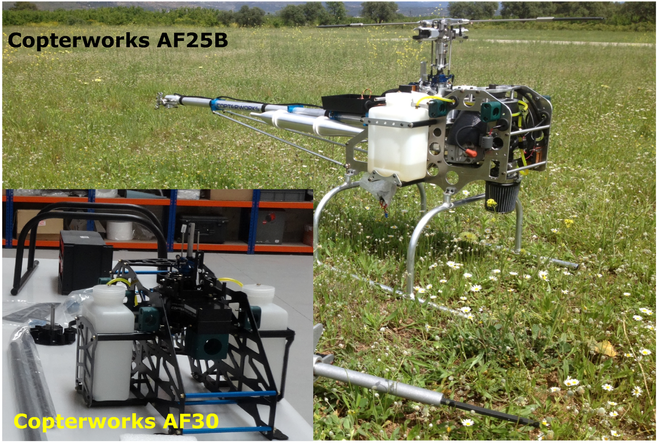
Considering the fact that a clear area may not always be available near the operation zone, from where a fixed wing aircraft could take off and land, we have chosen a rotary wing solution. Features such as hover, slow speed and maneuverability make rotary wing aircraft the best option for our development. Specifically, we have selected the AF25B model helicopter and its evolution AF30 from the Copterworks company (see Figure 2). Using AF25B, we studied all the airframe specifications and performance in RC mode. Based on that experience we implemented the full UAS integration on top of the AF30 airframe. Both platforms have similar specifications; they have a payload capacity of around 10 kg, a dry weight of 16.12 kg (in the case of AF25B) and an endurance of around 55 min with 3.8 L of fuel. Both AF25B and AF30 are provided without any electronics, therefore the first step is the integration process and electrifying both platforms with the suitable servomotors.
4. Servomotor Selection
Selecting the servomotors for the UAS is one of the most important choices. The servomotor converts the electrical commands generated by the autopilot into mechanical changes in the rotor position or energy produced by the engine which will lead to the actual vehicle movement. The failure of any of them, especially in a helicopter, would produce a total loss of the platform.
In a helicopter, there are three different mechanical components that require a servomotor installation: the main rotor, the tail rotor and the engine; each one of them has different servomotor requirements. Common characteristics for the three types of servos are reliability, sturdiness, tolerance to vibrations, precision and high torque. To assure a high level of reliability, all of them should be made of metal gears, ball bearings and a brushless motor. All selected servos are digital, which have a much smaller deadband, faster response, and a more accurate and better holding power than analog servos. All servos were provided by the company Savox [24] which has demonstrated reliability over time in this field.
Keeping all these requirements in mind, the following servomotors were chosen:
- Main rotor—3 servomotors required. They are exposed to high loads and vibrations. They should be fast enough to perform all the autopilot command with high static and dynamic holding torque. The servo selected was the SB-2270-SG which has 320 Ncm torque and speed of 0.12 s/60° at 7.4 V, steel gears and a partial metal case.
- Tail rotor—1 servomotor required. The main demand for this servo is the speed. It must be ultra-fast to be able to perform the continuous tail adjustment demands from the gyroscope. The servo selected was the SB-2271-SG which has a speed of 0.065 s/60° at 7.4 V.
- Throttle—1 servomotor required. Not a lot of torque is needed for this motor, but precision and speed are necessary. This servomotor moves the throttle lever commanded by the autopilot, which is continuously trying to maintain constant rpm in the rotor (i.e., constant engine rpm). The servomotor selected was the SB-2271-SG, the same as the one used in the tail.
5. Avionics Location
The next step in the integration process when designing a UAS helicopter is to decide where the avionics components should be located inside the airframe. Different boxes have been created to accommodate all the necessary avionics: One box dedicated to the electric power management, another box to manage the autopilot systems, another to store the propulsion system electronics (EFI) and a final one for the on-board mission computers.
The Copterworks AF25B and AF30 airframes are designed to carry the payload mounted in the front. The helicopters are designed to be weight-balanced, taking the main rotor as the center of mass. A non-balanced platform results in more stress on the mechanical components and much less control for the autopilot due to the continuous torque compensation. Both AF25B and AF30 are equipped with an extensible frontal support that allows the load to be moved to keep the proper weight balance. Given this flexibility to move the load, the front side has been chosen to support the payload (on-board mission computer box and the electro-optical sensors), which is susceptible to being changed between different missions. The rest of the avionics boxes, that will be always required in all missions, should be located near the main rotor to maintain the platform’s balance. Figure 3 shows the location of the main avionics and boxes.
The power supply box is located close to the alternator and in a place with good ventilation which will help to dissipate the heat generated by the power supply systems. The autopilot box is located next to the main rotor and mounted to minimize vibration with multiple different damper mounts (see next subsection for further details). It is essential to have the autopilot well isolated from dangerous vibration levels to guarantee high quality measurements from the embedded inertial sensors. High vibration levels generate incorrect measurements, making the platform unstable. The autopilot box also acts as a power supply distributor. The high voltage power supply generated in the power box is distributed by means of different secondary low-voltage regulators to all the systems needed in the helicopter (ADS-B, laser altimeter, magnetometer, on-board mission computer, etc.).
The Electronic Fuel Injection box (with the Engine Control Unit inside) is located on the right-hand side, while the laser altimeter is on the left. The ADS-B module is located behind the right fuel tank and the magnetometer (connected to the autopilot) is placed on the helicopter’s tail.
6. Anti-Vibrations Design
Analysis shows that the UAS airframe is subject to two different sources of vibration. Oscillation frequencies of around 155 Hz are generated by the engine and frequencies of around 24 Hz are generated by the main rotor. Engine vibration amplitude is negligible compared with the 24 Hz amplitude generated by the rotor system, which are the main frequencies that need to be dumped.
As mentioned before, EFI and regulator boxes are isolated by “standard” rubber isolators to avoid mechanical damage from strong vibrations. However, the autopilot box is different. Inside the autopilot there is an Inertial Measurement Unit (IMU) that is the heart of the autopilot. Inside it, there are three gyroscopes and three accelerometers that must be isolated as much as possible from external disturbances. Therefore, these isolators should be carefully selected and validated, or the Kalman filter algorithm executed by the autopilot could be saturated.
In our case, two different isolator types have been tested: wire rope isolators [25] and silicon radio control dampers with a resonance point of 9.5 Hz. This resonance point is far away from the 24 Hz and 155 Hz vibration frequencies that we intend to dump. Wire rope isolators are widely used in military applications and have a very good performance. It is possible to select the size of the wire, number of turns and diameter of the wire to comply with the dumping specifications. The silicon dampers are also widely used to stabilize gimbal cameras in multirotors and can be found in any ordinary radio control hobby store.
To test the isolators, several flights were performed with the AF30 model in manual mode at different rotor spin values in two different flight tests, first with wire rope isolators and in the second with silicon dumpers.
Vibration data is obtained on the natural axes of the autopilot without regard to its mounting orientation. Vibration data has been taken with the rotor turning at 1350 rpm (nominal value), 1300 rpm, 1275 rpm (minimum value of rpm observer in previous radio control test flights) and 1250 rpm.
On Figure 4a, the acceleration values using the wire rope isolators are illustrated, while on Figure 4b values using the silicon dumpers are also shown. In this case and for this vehicle, the silicon dumper provides better behavior than the wire rope isolators. The vibration amplitude in the X-axis has been reduced and the whole vibration response in the Y-axis is clearer than when using the wire rope isolators.
7. Helicopter Propulsion System
Engine reliability is probably one of the main problems in small- to medium-size UAS helicopters, using engines within the 28 cc to 500 cc range. The reason is that in these small sizes it is common to use a carburetor to feed the fuel to the engine. Although the carburetor works reasonably well at sea level and moderate temperatures, it begins to have drawbacks when working at higher altitudes and/or extreme temperatures.
7.1. Design of an Electronic Fuel Injection System
The combustion process in an engine is the reaction between hydrocarbons (Hx-Cx) and the O2 present in the air to form CO2 + H2O. The carburetor, or alternatively an Electronic Fuel Injection (EFI) system, prepares the air-fuel mix in the inlet pipe, within a narrow mixture margin. In the case of petrol, this ratio, in mass, is 1 part of fuel for each 14.7 parts of air. This is called a stoichiometric mixture and is the theoretical ratio that leads complete combustion without leaving behind HC or O2.
- A lean mixture (more air than fuel) is difficult to burn, and can produce a flameout.
- A slightly rich mixture is easy to burn, and as a benefit, the excess of fuel cools the engine, absorbing heat (due to vaporization enthalpy).
- A very rich mixture (much more fuel than air) is difficult to burn, and cools the engine down too much, which can produce a flameout.
In summary, what we need for our engine is a slightly rich mixture in any case. A simple carburetor is a mechanical device that works using the Venturi effect, and therefore provides the fuel mixture depending on the speed (volume) of air along the carburetor body. The fuel dispensed in the carburetor from low to high air speeds does not fit with the engine fuel requirements. In fact, setting the carburetor to work in a convenient air-fuel ratio at wide open throttle will produce a rich running in the medium range (where a UAS works most of the time). This is not a major problem at sea level, other than the high fuel consumption.
Air density decreases with altitude, therefore the density is lower than at sea level. The carburetor does not have this effect to account for, and enriches the mixture with the altitude. The same volume of air and fuel is dispensed as at sea level, but with a lower air mass due to decreased density, and as a result an excess of fuel in the mixture. In the best case this effect will simply imply a high fuel consumption, but in the worst case, engine shutdown. In a similar way, temperature affects air density, which will also impact the quality of the mixture, although to a lesser extent. The EFI adapts much better to the engine fuel requirements and solves problems with both altitude and temperature. Quite a lot of work has been done by the industry, such as developing EFI engines [26,27,28]. However, at this moment, there are no commercially available EFIs for most helicopter engines (like our Zenoah G800BPU—80 cc) around the world which also fit into both the AF30 and AF25B chassis. Within the EFI, different sensors read the crank position, engine temperature, ambient temperature, and pressure and throttle position to generate the injector trigger. The Engine Control Unit (ECU) determines the instant at which the fuel is injected to control the air-fuel mixture and its duration. This means that the exact fuel quantity is decided at each engine revolution based on the sensor readings, and the mixture can be kept close to stoichiometric in any operative situation. Overall best fuel economy is attained when exploiting an EFI in a UAS [29]. Moreover, safety is greatly increased as the EFI system will change the mixture to avoid the shutdown of the engine in flight due to large altitude or temperature changes.
The injector used in the integration is a piezoelectric fuel injector with 80 g/min mass flow. A piezoelectric injector provides highly controllable force and fast response time compared with other types of actuators such as hydraulic or pneumatic [30,31]. As mentioned before, the carburetor works by the Venturi effect, caused by a narrowing inside it. When the air is accelerated in the narrowing, it cools. This can cause the carburetor to freeze, leading to engine shutdown. The EFI also avoids this problem, because the narrowing does not exist; basically, it is not needed because the fuel is injected by an injector.
The EFI developed for our helicopter has been tuned for this specific engine. “Standard” EFI systems [32] employ large pumps working at full range with mechanical pressure regulators that vent the excess of fuel back to the tank. Our system uses an electronically-controlled “state of the art” brushless geared pump in closed loop via a pressure sensor, which allows low power consumption for the EFI system. As illustrated in Figure 5, the EFI system is connected to an rpm sensor located in the engine, to a 12 V power supply connector and to the autopilot by means of a CAN bus. In this way, the autopilot system can forward critical engine information such as rpm, fuel flow, etc., down to the ground control station.
Finally, the helicopter propulsion system has a commercial ignition control system (Capacitor Discharge Ignition [CDI]) which can control the two spark plugs in the two cylinders of the Zenoah G800BPU engine. Petrol engines need a spark to ignite the air-fuel mixture inside the cylinder and generate the work. The stock Zenoah engine was equipped with a magneto ignition system that was changed by a CDI electronic system. In a magneto ignition system, the point where the spark ignites is always the same (the coil is fixed to the engine crankcase and the magnet to the crankshaft), and does not vary with the engine speed. Therefore, we need to control the instant when the spark ignites for good engine efficiency at any engine speed. The CDI is an electronic ignition system that uses a Hall sensor to know the crank position. This signal is electronically delayed as needed depending on the engine speed, and activates a transistor. Additionally, the CDI generates a digital signal on each turn, that is used as input by the EFI and autopilot. The advantages that justify its choice are:
- Lightweight and low consumption.
- Timing controlled by microprocessor. (The spark occurs always at the right moment, improving power and fuel efficiency.)
- High energy spark in any condition (good starting, idling and engine performance).
- Self-generated rpm signal for EFI and autopilot. (No external devices are needed.)
On the other hand, the main disadvantage is the power supply needed to work it. In the case of the helicopter integration this is not really a disadvantage, because the power supply is readily available. To sum up, adding a EFI, ECU and CDI provides important benefits in terms of fuel economy, safety of operation and auto engine setup at high altitude and different temperatures.
7.2. Configuration of the Electronic Fuel Injection System
The configuration and fine tuning of the EFI requires identifying the air quantity that the engine is sucking at each spark plug ignition. The maximum air volume will be the equivalent to the engine displacement (80 cc in this case). The actual air being sucked will be represented by a percentage of the total engine displacement (from 0 to 100).
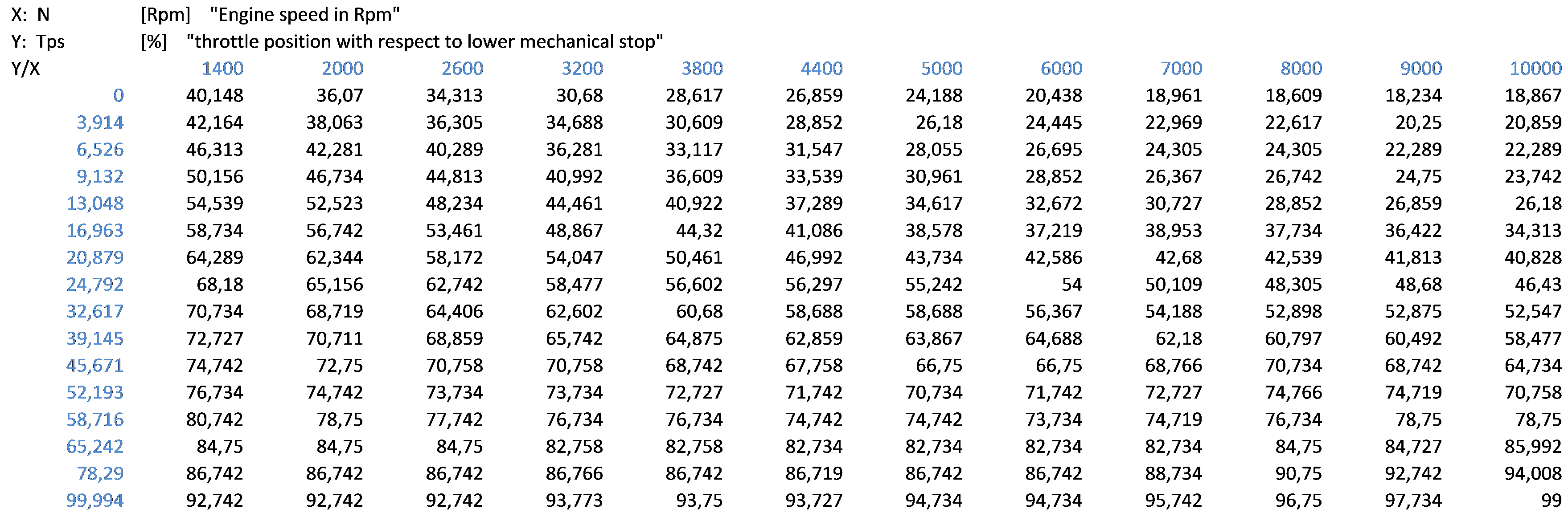
The quantity of air sucked by the engine mainly depends on the engine load, and the engine speed (rpm). There are two possible ways to estimate the engine load. One is to measure the intake pressure, and the second is to measure the actual throttle position. The intake pressure is a good way to estimate the engine load in four-stroke engines. However, for two-stroke engines (this is the case for the Zenoah G800BPU), this is not accurate enough at high speeds, and thus sensing the throttle position is preferred. This is accomplished by a Throttle Position Sensor (TPS) which is a position encoder connected to the throttle shaft. As a result, in our case the normalized load will be estimated by both the TPS and engine speed. This method is called the Alpha/N.
Figure 6 describes a preliminary normalized load characterization based on TPS and engine speed (Alpha/N method). The data is represented by a 12 × 16 table (sometimes also referred as “TPS maps”). The interpolation between samples is employed to obtain a continuous mapping surface.
For each possible intersection of TPS (Y axis) and engine speed (X axis), there is a normalized value that represents the estimated volume of air sucked by the engine in that particular cycle (as a percentage of the engine capacity). Based on this information and the additional data captured by the external sensors (barometric pressure, air temperature, engine temperature, etc.), the EFI calculates the actual air mass being sucked by the engine. The combination of the gas pump pressure and the actual injector size will determine the time (milliseconds) that the injector has to be opened to inject the exact amount of fuel to obtain the targeted mixture. This is an empirical analysis that depends on each engine, exhaust system, etc., and the final settings of the TPS map are only reached after multiple fine-tuning iterations. Due to industrial copyright issues, only a preliminary EFI calibration table is provided.
To achieve the desired fine tuning, a wideband O2 sensor (also known as a lambda sensor) has been connected at the exhaust system. Running the engine in a stationary state and reading the lambda factor, we can determine if the engine is running rich or lean in fuel. Ideally the lambda factor should read 1, which means 1 part of fuel for 14.7 parts of air for petrol and consequently indicates that there is no lack or excess of air in the mixture. In real life, a lambda factor of 0.9 for a full throttle setting is desired, as this improves the cooling and reliability of the engine.
In the final part of this section we will demonstrate how the lambda factor is kept constant at around 0.9 for different phases of the helicopter flight.
7.3. Quantify the Electronic Fuel Injection Fuel Economy
The following experiment has been performed using both the AF25B and AF30 in order to quantify the benefit of integrating an electronic fuel injection system instead of the original carburetor provided by the manufacturer.
The AF25B model was calibrated and configured as it comes from the factory (tuning the carburetor performing different manual flights). On the other hand, the AF30 model is configured with the previously described EFI system, which is tuned to reach a balance between efficiency and engine reliability (a lambda factor target of 0.9). In order to perform the experiment with consistent initial conditions, both helicopters are configured with the same take-off weight without fuel (27.57 kg). To achieve this setting, extra weight was added to the AF25B model as illustrated in Figure 7.
After adjusting the helicopter and being sure of achieving a stable flight, the tanks were removed and emptied, then loaded with 2 L of fuel. The helicopter was then flown in stationary mode (measuring the time) until the level was low enough to land safely. The remaining contents were removed, measured, and subtracted from the initial 2 L to find out how much fuel was consumed in the measured time. In both cases the rotor was kept stable at 1360 rpm. Both flights were carried out in manual mode and by the same pilot who is experienced in helicopter flights.
The flight with model AF25B produced the following results illustrated in Table 1.
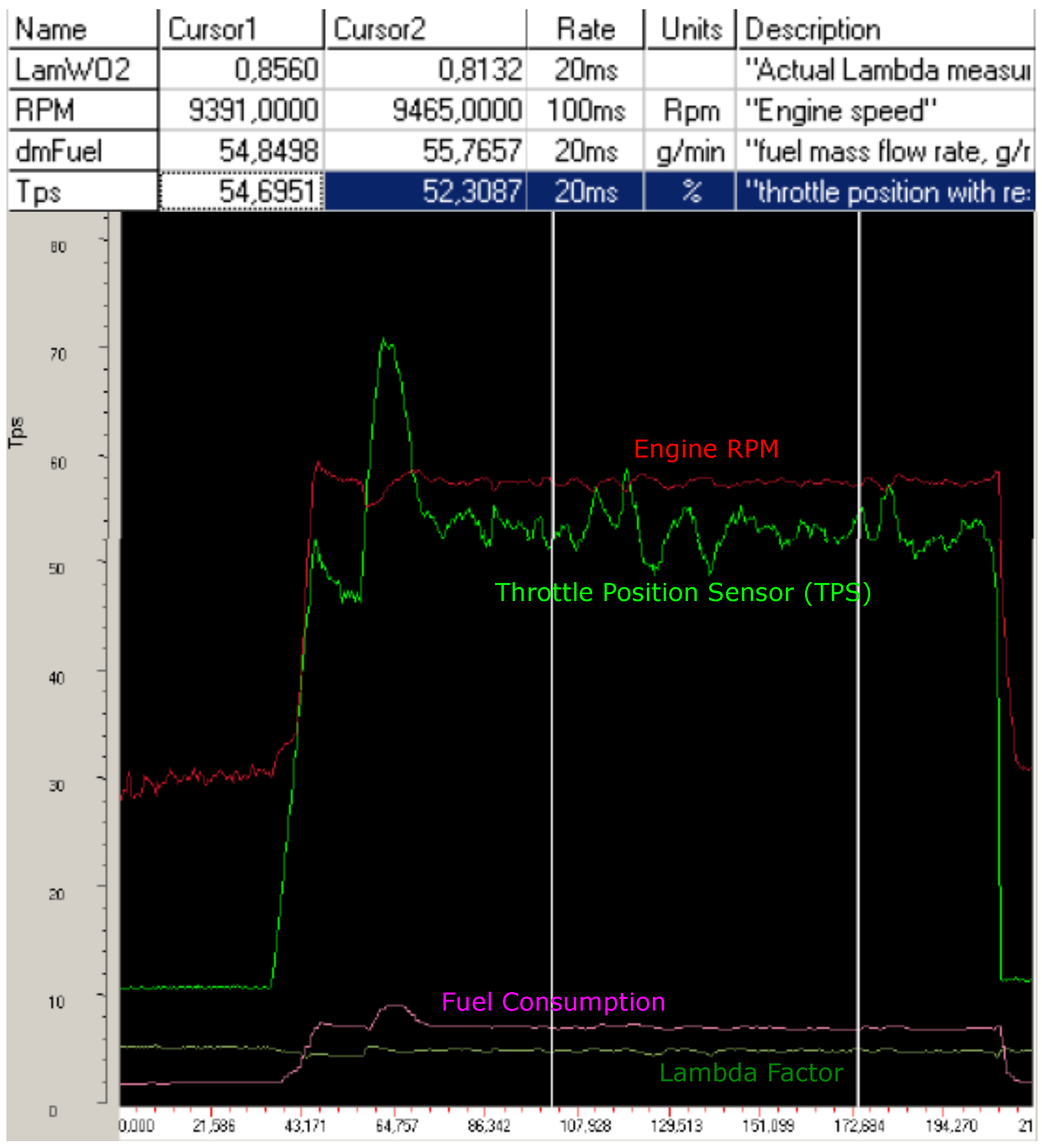
The flight with model AF30 produced the results illustrated in Figure 8. Note that the results shown in Table 1 and Figure 8 are made with the same atmospheric conditions. The fuel mass flow rate was around 55 g/min, with a fuel density of 0.75 which represents around 73.3 mL/min (flying with a lamWO2 setting close to 0.85). This means a reduction in fuel consumption of 27.3% compared to the carbureted engine. Note that the lambda factor remains constant for different phases of the flight and how the helicopter engine governor keeps a constant rpm acting on the TPS.
This experiment demonstrates the benefits achieved in terms of fuel economy. However, it should not be forgotten that incorporating an EFI into the integration eliminated the need to reconfigure the engine in the case of varying altitude and ambient temperature conditions. That is, the engine will keep working with optimum conditions regardless of the flight location and ambient temperature (although the temperature and air density may affect other subsystems like the lift provided by the main rotor). We perform flights and bench testing to validate the propulsion system in different density altitudes and temperatures. Bench testing was made to prove the altitude compensation. The experiment consists in to connect the engine inlet to a tank which is opened to the atmosphere via a faucet. With the engine running and closing the faucet, a drop in the pressure is generated inside the tank, (from where the engine sucks the air) simulating a high altitude flight. The lambda sensor readings were correct at any time. As far as temperature conditions is concerned, the system has been flown from 3 °C to 41 °C with no issues at all.
8. Helicopter Power Supply System
All the helicopter subsystems require an efficient, stable and reliable electrical power source. A power supply system based only on batteries could be an efficient way to power all the avionics subsystems and servos but could become a limitation when a UAS is to be set up for a long endurance mission, equipped with a great variety of sensor and computational capabilities.
8.1. Requirements and General Architecture
In order to design the power supply system, the total power consumption of all the on-board subsystems, both maximum and average consumption, must be taken into account. Table 2 details the power consumption of all on-board electronic components; note that several consumption estimates have been made.
The power consumption of the servomotors is estimated considering all the motors to be equal to cyclic servomotors because they are the only ones for which the manufacturer provides detailed information. This represents a worst-case scenario as these servomotors are the ones that support large loads and thus induce higher consumption. The maximum servomotor power consumption should only be observed if there is a mechanical failure or if a wrong command is sent from the autopilot.
In order to determine payload power requirements, the following factors have been used as a reference: the power consumption from previous developments in which an integrated system was included with two cameras (one visual and a second thermal one), a multipurpose processing unit with two different CPUs and independent communication channels such as Wi-Fi and radio modem.
With the current nominal power consumption, it may possible to energize all systems for the duration of the mission (one hour) exclusively using batteries. However, the large battery weight will indeed reduce the maximum weight available for mission payload. Seeking to better balance weight distribution among components, we decided to combine a small battery in our power system to support instantaneous peak power requirements and a power generator to cover long-term requirements. This allows us to reduce the capacity of the battery and improve the system reliability having a redundant power supply system. Given that there are not many power systems for UAS available in the market which integrate both technologies, the system was therefore developed from scratch focusing on the possibility of enabling long endurance missions.
The system generation consists of a three-phase brushless generator connected via belt and pulley to the combustion engine. The generator is connected to a microprocessor-controlled switching regulator which stabilizes the voltage from the three-phase alternate current (AC) to 28 V DC with a maximum continuous power of 300 W. The regulator includes a built-in system that charges the on-board battery and avoid overcharging it (see next subsection). If, for any reason, the power consumption at one point exceeds the regulator capacity, the battery would provide the additional current needed. Once the peak consumption disappears, the battery will be recharged by the generator. In the case of failure in the generator system, the UAS could continue flying exclusively powered by the battery. In this situation, the on-board mission computer will be switched off automatically and the UAS will return home as soon as possible. The system generator is complemented by a 28 V LiFePo4 battery with 2.5 Ah (see Figure 9).
The helicopter power supply system is accommodated in the power supply box and partially in the autopilot box (see Figure 3). In this last box are located the different power regulators which will step down the 28 VDC for the different helicopter subsystems. Basically, the UAS uses three different working voltages: 28 VDC, 12 VDC and 7.2 VDC.
- 28 VDC—This is generated by the system battery-regulator. It is not used directly by any consumer. Two different power voltages are regulated from the 28 V power source (7.2 V and 12 V).
- 12 VDC—This source consists of two redundant and independent switching power supply lines (maximum 12 A each). In the event that one of them fails, it should not affect the other line, which will be capable of powering the overall system by itself. This source powers the autopilot, laser altimeter, ADS-B, magnetometer and Electronic Fuel Injection (EFI).
- Secondary 12 VDC—Another single power supply line with a maximum of 12 A and no redundancy is provided to power the payload and the on-board mission computer.
- 7.2 VDC—This source consists of two redundant and independent switching power supply lines (a maximum of 12 A each). In the event that one of them fails, it will not affect the other one, which will be capable of powering the system by itself. This source powers the servomotors driving the mechanical controls, the CDI, the fuel pump and its controller.
This layout minimizes the possibility of a power blackout in any of the regulated power supplies, except for the payload power supply, which is not redundant. Failing to energize the payload is not considered an emergency failure; therefore, we have not considered that this power line must be made redundant.
8.2. Battery Selection
The batteries that have been chosen are eight LiFePo4 [33] cells (see an example pack in Figure 9). Although lithium cobalt oxide batteries have a higher energy density, around 200 Wh/kg compared to 120 Wh/kg of LiFePo4, they have a number of advantages that justify their choice, for example:
- They have a nominal voltage per cell of 3.3 and 3.6 at maximum charge voltage, that means that using eight cells gives us the correct voltage for the aeronautical standard of 28 V at maximum charge voltage.
- In case of overload, over-discharge, short circuit, etc., the cathode does not burn, as happens with the lithium cobalt oxide batteries.
- They are not prone to the “thermal runway” like their lithium counterparts.
- They have a longer life cycle; that is, they can be recharged more times (less than 5% loss in 550 cycles [33]).
As has been mentioned before, the LiFePo4 energy density is below lithium cobalt oxide but well above lead (40 Wh/kg), nickel–cadmium (60 Wh/kg) or nickel–metal hydride (80 Wh/kg).
For all the reasons given above, we believe that the LiFePo4 is the most suitable battery selection for our integration.
8.3. Generator Design
To perform the hardware selection, we will set up our operational requirements to be able to perform a one-hour mission, assuming that all the systems included payload are running from take-off to landing, with an average power consumption of 123.4 Wh. In case of non-critical system failure, the payload equipment is turned off, reducing the power consumption to 48.4 Wh (see Table 3).
The maximum time in emergency mode will be 30 min, assuming that is the farthest distance reached in a one-hour mission. Also, 15 extra minutes have to be considered to perform vehicle checks before the flight, in which the avionics are powered on but the engine is off. To estimate the energy requirement of batteries, the capacity is oversized by 20% to take into account the capacity losses by temperature changes, battery degradation by charge/discharge cycles and variations in nominal power consumption.
In order to dimension and justify the generator design, we will compare the two potential solutions which could be integrated: (1) on-board generator with backup battery and (2) only batteries.
Solution (1) implemented a mixed generator plus battery. In this solution, a battery is required to power all the avionics in the checking phase and also in the emergency state if the emergency state is raised by generator failure. On the other side, a generator is used to power all the systems during the mission and also to charge the battery. Taking into account that energy consumed during the checking phase is recovered through the generator during the flight, the battery only needs to provide energy to power the avionics during the emergency state. The backup battery, described in the previous subsection, is built using 8 cells with 26.4 V of nominal voltage and 2.5 Ah (providing around 66 Wh), enough to fly for a whole hour with the payload disconnected in the case of a generator failure (even in the case of a spent battery). The generator used in the helicopters has an output power of 280 W (because this is needed to power the payload and charge the battery). The generator weighs 400 g and the regulators 300 g As the weight of this battery is 600 g, adding accessories raises the weight to about 1400 g for the complete system.
Solution (2): Let’s suppose that we want to cover the energy needs with batteries only. This involves providing enough energy to power the system during the checks and the mission. The energy consumed in the emergency phase is not considered since consumption is less than the mission phase. To provide 162.60 Wh, at least 20 cells of 8.25 Wh each are required. The cell weight is 76 g; thus, the total weight of the complete power system will be around 1600 g. The solution 1 weighs less than solution 2 and, additionally, it is clear that the generator option will be always safer, as you have an unlimited power source, and in case of a failure, you only have to disconnect the payload, and return to land with the backup battery. Additionally, we are working on using the generator to start the engine from the GCS, and of course, this will make it worth using the generator option by itself.
The voltage produced by the generator depends on the electrical motor revolutions per volt (KV) and the helicopter engine rpm. Using the high KV generator has both advantages and disadvantages. The advantage is that the output voltage range at full engine rpm is similar to input voltage UAS equipment, and so a simple electronics it is needed to generate the required continuous voltage levels. The disadvantage is that the voltage is enough to power the systems only at full engine rpm, and power generated it is not enough for our application requirements.
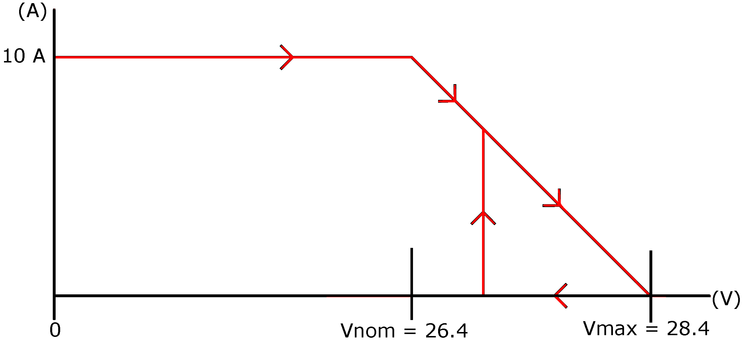
In our system, we decided to employ a powerful (1200 W) and low KV (KV 90) three-phase brushless generator that is able to generate 28 V at only 1750 rpm (even below the helicopter’s idle rpm). Problems arise when the engine gets up to 9450 rpm, where the rectifiers have to cope with voltages up to 150 V. Given the high-level voltages, we implemented a complex microprocessor-controlled switching regulator to manage the output power, and battery charging. The generator is connected to the regulator and the output of the regulator is connected in parallel to the 28 V battery. The nominal battery voltage for this pack (Vnom) is 8 × 3.3 = 26.4 V and the maximum charge voltage (Vmax) is 8 × 3.6 = 28.8 V. If the battery is under Vnom, the regulator will drain 10 amps to the system, and from Vnom to Vmax it will fall to zero. As soon as the voltage drops (due to the power consumption), the system will increase the intensity (see Figure 10). The system will self-regulate and will feed the system upon further demand from the payload, and will maintain the backup battery at least Vnom. If the power consumption at some point becomes higher than 280W, the battery will provide the additional power (up to 10 A) and the charge will be recovered as soon as the power consumption drops to nominal parameters.
9. Helicopter On-Board Mission Computation
Even though UAS are considered to be highly developed vehicles, they still rely on lots of manual pilot interaction, and little mission and flight-plan coupling. Automation and autonomy should improve this scenario [34]. Automation is understood as the capability of the UAS to perform certain tasks without requiring immediate pilot intervention, just his/her confirmation. Pilot supervision is essential, especially if these tasks will have a direct impact on the flight aspects of the UAS. This is to guarantee the soundness of whatever action is executed, as the UAS pilot is the person who is ultimately responsible for the safety of the flight.
Currently, fully autonomous UAS operations are not possible, even in isolated areas, due to missing certifications; hence, autonomy has to be introduced cautiously. The operation of UAS cannot be separated from the restrictions imposed by their introduction in non-segregated airspace [35,36]. Thus, autonomy will only be accepted if the behavior of the UAS is deterministic at all times, and the pilot in command/ATM authorities can understand the limits of that autonomy beforehand.
In the meantime, automation under the control of the UAS operator is the best option to increase the productivity of the systems. Employing reusable mission templates (or patterns) will also facilitate operator preparation. Mission templates will reduce the cost of each operation and will facilitate acceptance by the ATM authorities.
Nowadays, almost any electronic device has fairly powerful computing capacities due to the new families of computing processors embedded in mobile devices. However, almost no effort has been directed at permitting UAS to exploit these existing capacities.
On-board computation capacity could ease the transformation of the huge amounts of raw data that are computed by UAS (through cameras and other types of sensors) into valuable information while the UAS is still in flight. That early transformation provides multiple benefits to both the economic and operational efficiency of the system:
- It will reduce the volume of information that needs to be downlinked to the operator, thus reducing the economic investment and operative cost of the required communication systems.
- The earlier raw data gets processed, the faster results will become available, thus improving the economic efficiency of the UAS operation.
- Improved on-board processing will facilitate the identification of relevant situations during the UAS mission (like the detection of fire hot-spots or persons during search and rescue operations). That early detection could trigger a reorientation of the UAS mission objectives, especially if supported by automated processes and mission templates that could facilitate the operator’s decision process.
An analysis of the most common remote sensing missions [23,37] leads us to believe that most of them follow similar structures and are compatible from the point of view of the architecture of the mission system. It is the intention of the On-board Mission Computer box to develop this general architecture, providing scalable computation capabilities that facilitate the implementation of parameterized mission templates.
Figure 11 illustrates the diagram blocks of the On-board Mission Computer box and its main interactions with electro-optical sensors and the autopilot. The box interacts directly with cameras through a USB 3.0 connection. The raw data acquired by the cameras is geo-referenced using the “Secondary GPS and IMU” or directly using the autopilot telemetry. The box has direct access to the autopilot to get the autopilot telemetry on board or change the flight plan if this is deemed necessary. The co-processor board is in charge of providing the high-performance computation in the UAS. Most of the time, achieving high-performance computation requires specific hardware that is able to sustain high MIPS/MFLOPS per watt or extreme high performance in very specific operations. Several technologies are appearing with promising results for high-performance computing on unmanned platforms, especially multicore architectures, but also FPGAs and GPUs [38,39]. The computation box also employs a general purpose “Main CPU” (at this moment Intel NUC [40]) in case a non-urgent task is required, limiting the energy consumption; or a high-performance “co-processor board” Multicore/FPGA/GPU in case high performance is required and the hardware is available. Currently, we are working to integrate Xilinx’s Microzed board [41].
Finally, the onboard computation box provides communication capability based on the combination of a scalable set of technologies, depending on availability and the performance of the networks. The communication between the vehicle and the ground station could be performed through private radio networks using serial radio modems for low throughput and low latency communications while high throughput short range communications could be performed through Wi-Fi network by means of an IEEE 802.11 compatible board. The access to the mobile network is also supported using a 3G/4G compatible modem which provides connectivity to the internet. The 4G module attached to the onboard computer is the 4G ZTE MF823 modem. The access to the internet could be used to extend the range of vehicle and ground communication as well as enable the capability of sharing data among third party systems.
All this hardware is managed by a software architecture called RPAS Mission Management Architecture (RIMA) [42]. The RIMA is the set of available software components running on top of the Data Distribution Service (DDS) middleware to give support to most types of RPAS civil missions. RIMA has been designed partially following the guidelines described in [43].The middleware used is the Connext DDS from the company RTI Innovation [44]. It also defines their interrelations as a basic starting point for further development by users. Functionalities like enhanced flight plans, a mission control engine, data storage, high computation on board, autopilot management, etc. are offered.
10. Integration Validation and Fine Tuning Tests
After describing the integration process and all the subsystems, it is time to describe the tests developed to validate the helicopter integration. Different tests have been performed to check and fine tune each of the helicopter subsystems.
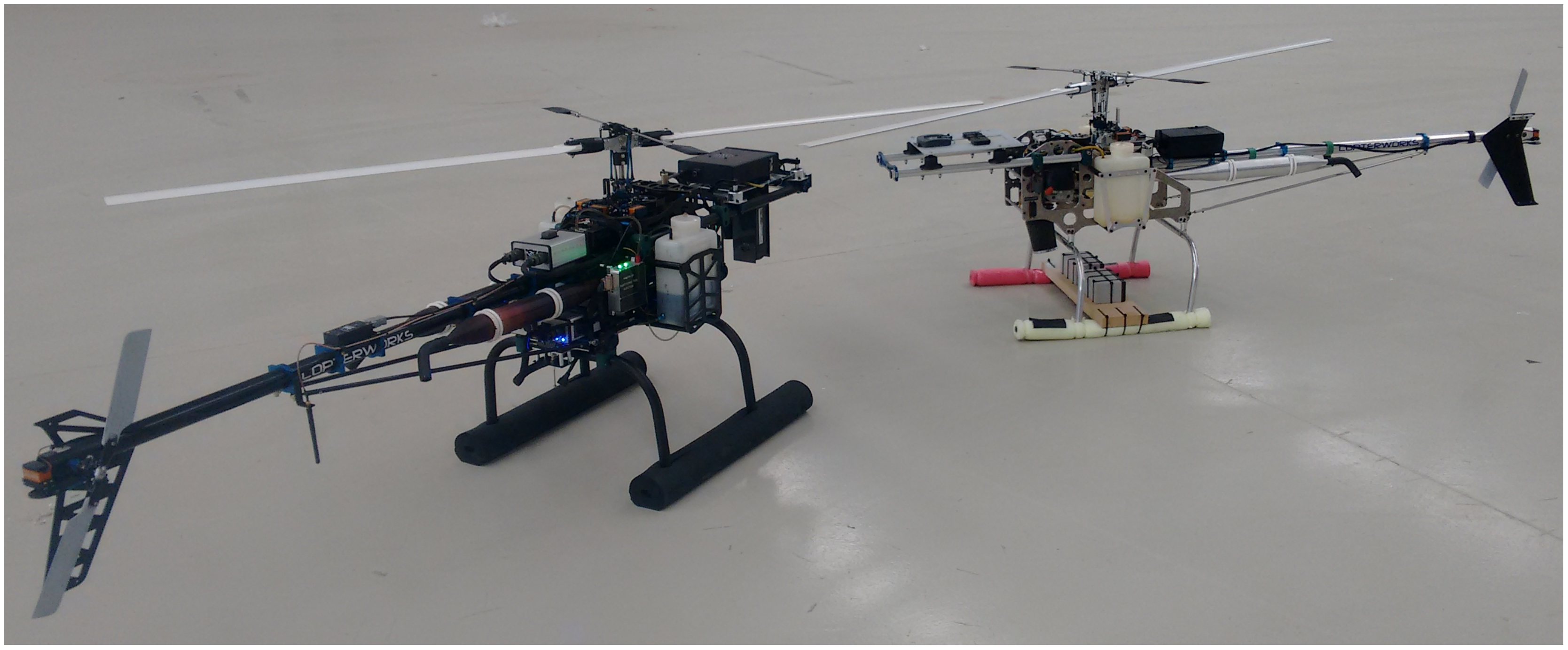
The first test flights have been performed successfully with all the components tested and installed in the Copterworks AF30. Figure 12 shows all those components installed in the helicopter and a video is shown in [45] with the first autonomous test flight that was recorded.
The validation and fine tuning of EFI systems were carried out as follows. First, the EFI, ECU and CDI were adjusted at the test bench. Before proceeding further, it was imperative to have a “running engine” which has to be done assuming volumetric efficiency for the engine. Once this work was completed and with the engine running reasonably well, final tuning was implemented using a wideband lambda probe, which measures the excess or lack of oxygen in the exhaust gases (lack of oxygen means too much fuel, and vice versa). Using this probe and testing the engine in different conditions, an EFI preliminary configuration table was derived (see Figure 6). Additionally, the engine was run for about 15 h to ensure the best engine conditions for the first flights. Note that the lambda probe is used only for engine mapping in tests bench, and short stationary test flights. The standard working of the EFI with the two stroke engine is in open loop (no lambda probe installed).
The first flights were executed with the lambda probe on board, sending the engine parameters to the ground stations (rpm, engine temperature, intake pressure and oxygen concentration) and allowing the “fine tuning” of the EFI during flight in different flight conditions. The configuration aim was to target a lambda factor of 1 (which means stoichiometric conditions); but practically the target achieved was a lambda factor of 0.9, which assures the cool operation of the engine.
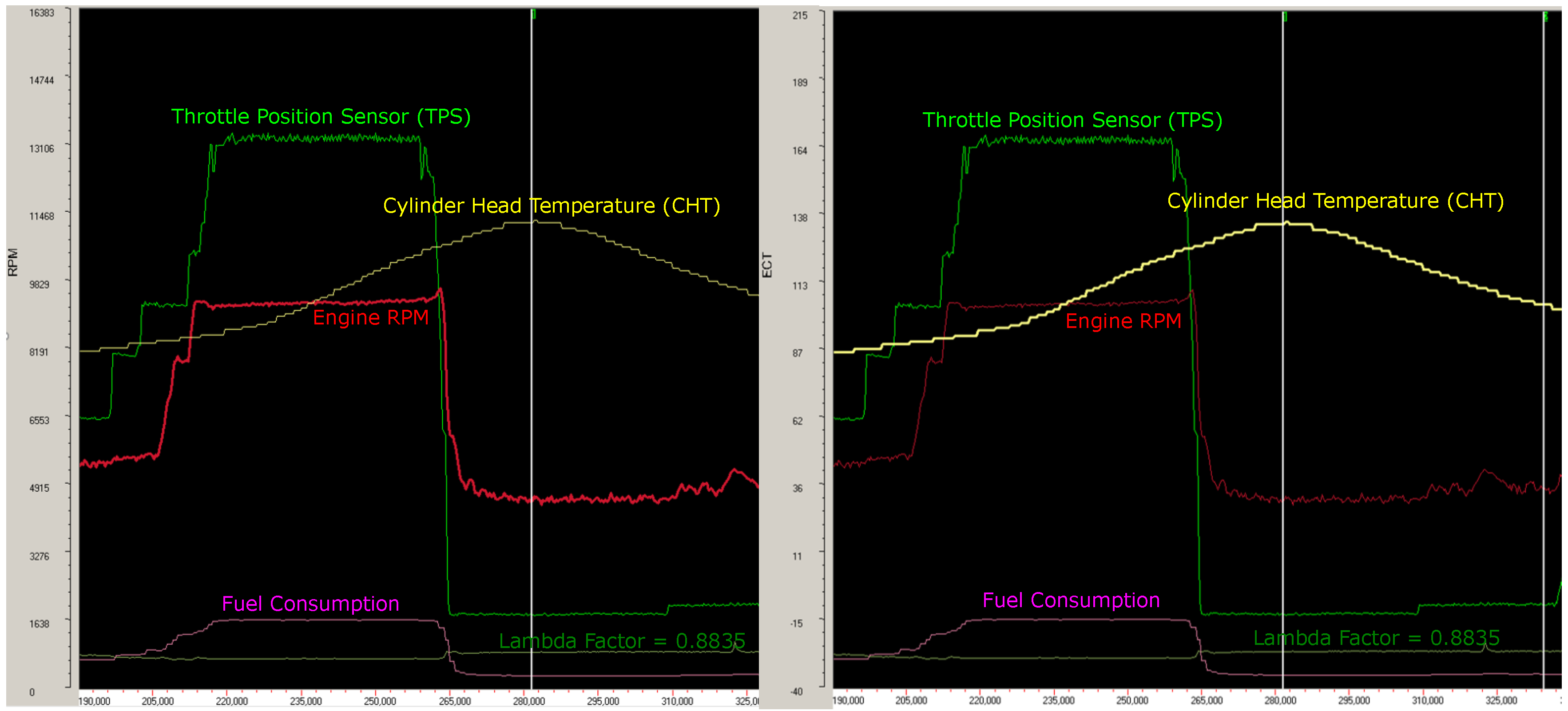
Figure 13 illustrates the rpm and cylinder head temperature parameters of one of the test flights. The flight corresponds to a simple pre-acceleration, climb, one-minute stationary flight, landing, and some time idling on the ground. Other parameters, such as fuel consumption, TPS, or lambda factor, are also represented in Figure 12 in order to see the relationship between them during the flight; however, those parameters are not to scale. Note that the engine governor maintains constant engine rpm independently of the blade pitch. The cylinder head temperature range is within nominal values. The temperature highest point is the normal working temperature, and for a longer flight it would not increase more than that. Fuel consumption is directly related to rpm and throttle position. Finally, it is validated that a lambda factor remains constant during the whole flight and close to 0.9. Regarding to the lambda factor, notice the step change in the value from full rpm to idle. The reason for this is that the desired lambda for full rpm is a little different to idle. The desired lambda in full rpm is 0.85 which involves a slightly rich mixture. With slightly rich mixture we have better engine cooling due to the fuel that is not burned, but vaporized (absorbing heat that is evacuated via the exhaust). A variable lambda is a good strategy for any high-performance two-stroke engine. At idle, the desired lambda is set to 0.9, using leaner mixtures because there are no overheating problems and we can provide better idle stability.
After this final tuning has been completed, the system will adapt to the different altitude and temperature conditions without the need to manually adjust it.
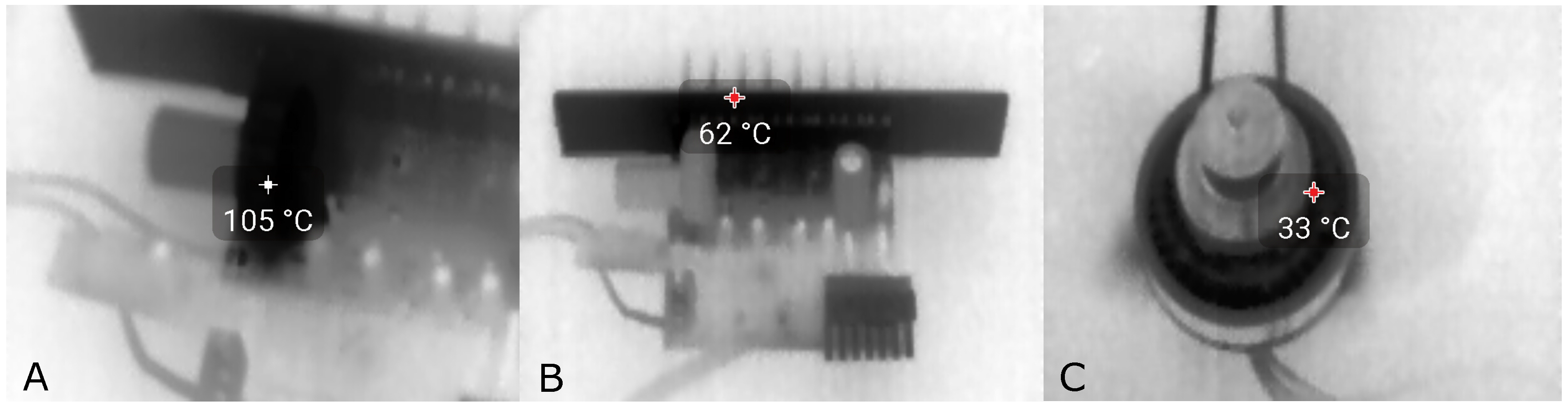
The validation and fine tuning of power supply systems were carried out as follows. The power system was developed in different phases. In the first phase, the output of the generator was characterized by means of an electric brushless motor working at same rotary speed as the optimal helicopter engine speed. In the second phase, following the same methodology, both the AC/DC converter and battery charger circuit were tested. Figure 14 illustrates the helicopter power supply main components thermography test. In the first tests, we could see that the coil was overloaded (see picture A in Figure 14), therefore we proceeded to replace it with another model. After the coil replacement, the warmest part was the MOSFET dissipation plate and the temperature was within safe limits. Finally, we checked the correct temperature on the generator (see picture C in Figure 14).
All these tests were made at a test bench, moving the generator with a spindle electric motor at 9450 rpm (actual engine speed of the helicopter). Halogen light bulbs were used to simulate the full load in the system (10A). After several hours of the test run, the system was cleared to be used in the helicopter. It is interesting to note that the cooling at the test bench was much worse than in the real system, with a forced cooling fan inside the case and the case cooled by the rotor airflow.
The last step was to test the complete power system with the helicopter on the ground, powering the avionics from external batteries. These tests were intended to validate the complete system in the helicopter in the presence of vibration and rpm variations. All these tests were performed successfully.
A similar process was followed to tune up the autopilot. First of all, the helicopter and the engine were modeled and validated using a Software in the Loop (SITL) simulator. Once the helicopter had flown correctly in the SITL simulator, tests flight in manual mode were performed to check the autopilot response to manual inputs. After these fights were performed successfully, the helicopter hover, auto land and auto takeoff operations were tested. Finally, a complete flight plan was uploaded to the autopilot and the helicopter was able to follow the flight plan without problems. This process it is not described in detail because is the autopilot manufacturer who provides the steps that the user has to follow to establish correct helicopter control and navigation.
11. Conclusions
There are many aspects to consider when designing a UAS from scratch. This paper describes the complete integration process and, as main contribution, illustrates the benefits of adding three additional systems: the EFI, the power generator and the on-board computer in the UAS. These three systems are currently not included in the majority of the mini and small UAS, despite they provide very interesting benefits to these UAS.
Incorporating an electronic injection in the internal combustion engine of the UAS has resulted in a much improved fuel economy, with fuel saving above 25%. Less fuel consumption allows longer flight times and the increase of the mission range. Alternatively, the requirement of less fuel can compensate the weight of the EFI system or even reduce the take-off mass of the UAS. Moreover with the EFI safety is improved because the reconfiguration of the most suitable mixture of fuel and air is automatically selected. Also because it avoids the freezing of the intake fuel. The small size of the proposed system makes the EFI a basic system to consider for practically all mini UAS.
The same holds about the addition of the power generator. The benefits of such system are the capacity of charging the batteries during the flight and the safety increase given by the redundancy of the power sources. A power generator allows to embark many types of payload which otherwise could be disregarded because the high demand of energy consumption. The integration of both the EFI and the power generator provides a very relevant increase of the mission range and time limits.
Finally, the on-board computing system is a fundamental part to be able to increase of level of automation of the UAS mission. The computing system is an independent layer from the flight management system, not interfering in the safety of the flight. It facilitates a more dynamic concept of operation, being able to execute more sophisticated algorithms and increasing the level of automation of the mission. At the same time, the computing systems reduces the required amount of information exchanged between the air and the ground parts of the UAS, reducing in this way the power consumption but also the possibility of communication errors and/or interferences.
The proposed UAS hardware architecture shall finally be accompanied with a distributed software architecture, suitable for increasing the mission automation and to meet the desired concept of the operation. As immediate future work we will start working on the software architecture which will increase the added value to the entire UAS. Other future works include the even more miniaturization of the three avionics systems proposed to make them available also to smaller UAS then the frames selected in this work.
Acknowledgments
This work was partially funded by the Ministerio de Economia y Competitividad of Spain under contract TRA2016-77012-R. Furthermore, the authors would also like to thank Mr. Jose Maria Tierra, Daniel Fernández and Miguel Angel Gomez, from MAGline, who assisted in the design and the whole helicopter integration.
Author Contributions
A.G. configured and integrated the autopilot and helicopter servo motors. He also design the anti-vibration system. F.B. developed the helicopter propulsion system. In the helicopter power supply system contributed F.B., R.C. and P.R. P.R. and R.C. developed the airframe selection, servo motor selection, avionics location and helicopter on-board mission computation. C.B. and E.P. provided general advice in all phases of the work and developed the mission requirement and concept of operation, introduction and conclusions. All the authors conceived and designed the experiments. F.B. and A.G. performed the experiments. P.R., R.C. and F.B. analyzed the experiment’s data. C.B and E.P. validated the helicopter integration process.
Conflicts of Interest
The authors declare no conflict of interest.
Abbreviations
The following abbreviations are used in this manuscript:
| MDPI | Multidisciplinary Digital Publishing Institute |
| DOAJ | Directory of open access journals |
| UAS | Unmanned Aircraft Systems |
| RC | Radio Control |
| LiFePo4 | Lithium Iron Phosphate |
| EFI | Electronic Fuel Injection |
| ECU | Engine Control Unit |
| ADS-B | Automatic Dependent Surveillance – Broadcast |
| BVLOS | Beyond Visual Line of Sight |
| BLOS | Beyond Line-Of-Sight |
| VLOS | Visual Line Of Sight |
| GCS | Ground Control Station |
| UA | Unmanned Aircraft |
| API | Application Programming Interface |
| CONOPS | Concept of Operations |
| PiC | Pilot-In-Command |
| AGL | Above Ground Level |
| ACAS Xu | Airborne Collision Avoidance System X (unmanned) |
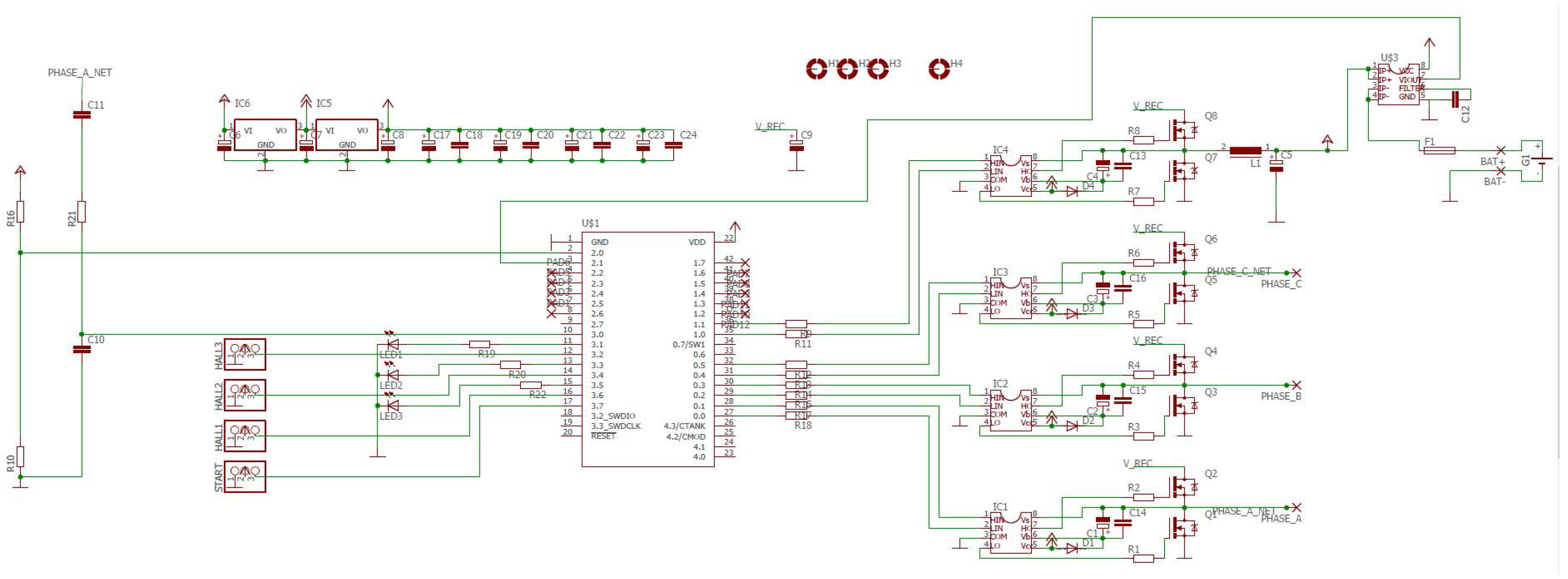
Appendix A. Power Supply Box Circuit Diagram
The Power Supply Box controls the current flow from the three phase brushless generator to ensure that the voltage of the battery is kept within safe margins and the consumers are provided with the required power. The circuit consists of the following elements:
- 8 x N-channel power MOSFETs with dedicated drivers.
- Cypress PSoC 4 series microcontroller with CortexTM-M0 CPU.
A basic schematic of the system of the finished circuit can be seen below.
The circuit can work in two very different modes:
- Generator mode
- Starter mode
Appendix A.1. Generator Mode
The generator mode is the default working mode for the circuit where the battery will be recharged by the generator.
The gates of Q1 to Q6 from Figure A1 are held low by the microcontroller. The current from the generator flows through the parasitic diodes of the MOSFETs and is therefore rectified and filtered (V_REC). The MOSFETs Q7, Q8, inductor L1 and capacitor C5 constitute a step-down converter. The output of the step-down converter is connected to the battery through a Hall current sensor IC and a fast fuse (F1).
The micro-controller works by dynamically adjusting the duty cycle of the step-down converter to achieve the required current flow (i_target) from the generator to the battery (see i_target vs v_bat graph in Figure 10).
Figure A1.
Schematic of the power supply system.
The required current flow is calculated as follows:
| if (v_bat<numcells*cell_vnom) |
| i_target=cell_icharge_max; |
| else |
| if (v_bat>numcells*cell_vmax) |
| i_target=0; |
| else |
| i_target=cell_icharge_max-cell_icharge_max* |
| (v_bat-numcells*cell_vnom)/(numcells*cell_vmax-numcells*cell_vnom); |
Where for our battery pack:
numcells=8, cell_vnom=3.3v , cell_vmax=3.6v, cell_icharge_max=10A.
In addition to that, if i_target ever reaches 0 (maximum battery voltage reached), then the step_down is completely disabled and only re-enabled once i_target reaches one-third of cell_icharge_max.
In the event of failure of the step-down charging system (too much current drawing to or from the battery), the fuse F1 would eventually disconnect the power box from the battery. The autopilot senses this situation and change to “battery only” emergency mode so the helicopter can land before full battery drainage.
Appendix A.2. Starter Mode
We are currently testing this operational mode. The power box hardware was designed so that it could eventually be used to start up the engine with the same brushless motor that is used as a generator.
The mode can be enabled once the generator rpm is measured and found to be 0 and triggered by a START signal sent to the power box from the autopilot.
References
- Dalamagkidis, K. Classification of UAVs. In Handbook of Unmanned Aerial Vehicles; Valavanis, K., Vachtsevanos, G.J., Eds.; Springer: Dordrecht, The Netherlands, 2015; pp. 83–91. [Google Scholar]
- Joint Air Power Competence Centre. Strategic Concept of Employment for UAS in NATO; Technical Report; NATO: Kalkar, Germany, 2010. [Google Scholar]
- Tang, S.; Zheng, Z. Platform and State Estimation Design af a Small-Scale UAV Helicopter System. Int. J. Aerosp. Eng. 2013, 2013, 13. [Google Scholar] [CrossRef]
- Chen, J.; Liu, H.; Zheng, J.; Lv, M.; Yan, B.; Hu, X.; Gao, Y. Damage Degree Evaluation of Earthquake Area Using UAV Aerial Image. Int. J. Aerosp. Eng. 2016, 2016. [Google Scholar] [CrossRef]
- Royo, P.; Barrado, C.; Cuadrado, R.; Pastor, E.; Barrao, F.; García, A. Development of a small UAS helicopter for remote sensing operations. In Proceedings of the 2016 IEEE/AIAA 35th Digital Avionics Systems Conference (DASC), Sacramento, CA, USA, 25–29 September 2016; pp. 1–9. [Google Scholar]
- Copterworks Inc. Copterworks Products. 2017. Available online: https://copterworks.com/products/ (accessed on 7 July 2017).
- Cloud Cap Technology. Piccolo II Product. 2017. Available online: http://www.cloudcaptech.com/products/detail/piccolo-ii (accessed on 7 July 2017).
- Magline UAS. Magline Composites and Systems S.L. 2017. Available online: http://www.magline.es/ (accessed on 7 June 2017).
- Renishaw Plc. Laser Altimetry for Manned and Unmanned Aircraft. 2017. Available online: http://www.renishaw.com/en/laser-altimetry-for-manned-and-unmanned-aircraft--25967 (accessed on 7 June 2017).
- Sagetech Corporation. Mode S Transponders. 2017. Available online: https://sagetech.com/ (accessed on 7 June 2017).
- Stark, B.; Stevenson, B.; Quan, Y. ADS-B for Small Unmanned Aerial Systems: Case Study and Regulatory Practices. In Proceedings of the International Conference on Unmanned Aircraft Systems, Atlanta, GA, USA, 28–31 May 2013. [Google Scholar]
- Coopmans, C.; Hoffer, N.V.; Jensen, A.M.; Robinson, D. AggieAir Unmanned Aerial System traffic Integration management: A Case Study with ADS-B Out. In Proceedings of the AIAA/IEEE 35th Digital Avionics Systems Conference, Sacramento, CA, USA, 25–29 September 2016. [Google Scholar]
- Perez-Batlle, M.; Pastor, E.; Prats, X.; Royo, P.; Cuadrado, R. Maintaining separation between airliners and RPAS in non-segregated airspace. Best paper in track award. In Proceedings of the 10th USA/Europe Air Traffic Management Research and Development Seminar (ATM2013), Chicago, IL, USA, 10–13 June 2013; Eurocontrol/FAA: Chicago, IL, USA, 2013. [Google Scholar]
- Laughter, S.; Cox, D. AirStar hardware and Software Design for Beyond Visual range Flight Research. In Proceedings of the AIAA/IEEE 35th Digital Avionics Systems Conference, Sacramento, CA, USA, 25–29 September 2016. [Google Scholar]
- Federal Aviation Administration (FAA). Concept of Use for the Airborne Collision Avoidance System (ACAS) XU; FAA: Washington, DC, USA, 2015. [Google Scholar]
- Gonzalez-Jorge, H.; Martinez-Sanchez, J.; Bueno, M.; Arias, P. Unmanned Aerial Systems for Civil Applications: A Review. Drones 2017, 1, 2. [Google Scholar] [CrossRef]
- Salami, E.; Pastor, E.; Barrado, C. Near Remote Sensing for Tactical Earth Protection. In Proceedings of the 33rd International Symposium on Remote Sensing of Environment, Stresa, Italy, 4–8 May 2009. [Google Scholar]
- Salami, E.; Barrado, C.; Pastor, E.; Royo, P.; Santamaria, E. Real-Time Data Processing for the Airborne Detection of Hot Spots. AIAA J. Aerosp. Inf. Syst. 2013, 10, 444–451. [Google Scholar] [CrossRef]
- Royo, P.; Perez-Batlle, M.; Cuadrado, R.; Pastor, E. Enabling Dynamic Parametric Scans for Unmanned Aircraft System Remote Sensing Missions. J. Aircr. 2014, 51, 870–882. [Google Scholar] [CrossRef]
- Royo, P.; Cuadrado, R.; Barrado, C.; Salami, E.; Perez-Batlle, M.; Pastor, E. Towards the automation of the UAS mission management. In Proceedings of the IEEE 32nd Digital Avionics Systems Conference, East Syracuse, NY, USA, 5–10 October 2013. [Google Scholar]
- Barrado, C.; Fuentes, J.A.; Salami, E.; Royo, P.; Olariaga, A.D.; Lopez, J.; Fuentes, V.L.; Gili, J.M.; Pastor, E. Jellyfish Monitoring on Coastlines using Remote Pilotes Aircraft. In Proceedings of the 35rd International Symposium on Remote Sensing of Environment (ISRSE 2013), Beijing, China, 22–26 April 2013. [Google Scholar]
- Royo, P.; Pastor, E.; Sole, M.; Lema, J.M.; Lopez, J.; Barrado, C. UAS architecture for forest fire remote sensing. In Proceedings of the 34th International Conference on Remote Sensing of Environment, Sydney, Australia, 10–15 April 2011. [Google Scholar]
- Salami, E.; Barrado, C.; Pastor, E. UAV flight experiments applied to the remote sensing of vegetated areas. Remote Sens. 2014, 6, 11051–11081. [Google Scholar] [CrossRef] [Green Version]
- Savox. Digital—Brusless Servos. 2017. Available online: http://www.savoxusa.com/Savox_Brushless_Servos_s/49.htm (accessed on 7 July 2017).
- ITT Enidine Inc. High Performance Vibration Isolation Products. 2017. Available online: http://www.enidine.com/en-US/Products/WireRopeIsolator/ (accessed on 7 July 2017).
- UAV Factory. UAV28-EFI Turnkey Fuel Injected Engine. 2017. Available online: http://www.uavfactory.com/product/77 (accessed on 7 June 2017).
- Power4Flight. UAV Engine Systems. 2017. Available online: http://power4flight.com/uav-engine-products/uav-engine-systems/ (accessed on 4 July 2017).
- NWUAV Inc. Compact Radial Engines. 2017. Available online: http://www.nwuav.net/nwuav/uav-products/CompactRadialEngines.html (accessed on 4 July 2017).
- ECOTRONS LLC. UAV Engine EFI. 2017. Available online: http://www.ecotrons.com/products/uav-engine-efi/ (accessed on 6 July 2017).
- Greg, S.; Satkosko, C. Piezoelectric Fuel Injector: Pulse-to-Pulse Coupling and Flow Rate Estimation. IEEE/ASME Trans. Mechatron. 2011, 16, 627–642. [Google Scholar]
- Hirmand, N.; Ridha, B.; Anthony, S. Development of a Piezoelectric Fuel Injector. IEEE Trans. Veh. Technol. 2016, 65, 1162–1170. [Google Scholar]
- Lenz, H.P.; Lenz, H.P.; Duelli, H.; Fraidl, G.; Friedl, H. Mixture Formation in Spark-Ignition Engines, 1st ed.; Springer: Berlin, Germany, 1992. [Google Scholar]
- A123 Systems. ANR26650 Lithium Ion Cylindrical Cell. 2017. Available online: http://www.a123systems.com/lithium-ion-cells-26650-cylindrical-cell.htm (accessed on 7 July 2017).
- Tomic, T.; Schmid, K.; Lutz, P. Toward a Fully Autonomous UAV: Research Platform for Indoor and Outdoor Urban Search and Rescue. IEEE Robot. Autom. Mag. 2012, 19, 46–56. [Google Scholar] [CrossRef]
- International Civil Aviation Organization. Cir 328 AN/190 Unmanned Aircraft Systems (UAS); Tech Report; ICAO: Montreal, Canada, 2011. [Google Scholar]
- European Commission. Roadmap for the Integration of Civil Remotely-Piloted Aircraft Systems into the European Aviation System; Tech Report; EU: Paris, France, 2013. [Google Scholar]
- Colomina, I.; Molina, P. Unmanned aerial systems for photogrammetry and remote sensing: A review. ISPRS J. Photogramm. Remote Sens. 2014, 92, 79–97. [Google Scholar] [CrossRef]
- Kok, J.; Gonzalez, L.; Kelson, N. FPGA Implementation of an Evolucionary Algorithm for Autonomous Unmanned Aerial Vehicle On-Board path Planning. IEEE Trans. Evol. Comput. 2013, 17, 272–281. [Google Scholar] [CrossRef] [Green Version]
- Benini, A.; Gonzalez, L.; Kelson, N. Real-time, GPU-based pose estimation of UAV for autonomous takeoff and landing. In Proceedings of the 2016 IEEE International Conference on Robotics and Automation (ICRA), Stockholm, Sweden, 16–21 May 2016. [Google Scholar] [CrossRef]
- Intel Corporation. Intel NUC Kit. 2017. Available online: http://ark.intel.com/products/84861/Intel-NUC-Kit-NUC5i5MYHE (accessed on 7 July 2017).
- Xilinx. MicroZed—Zedboard. 2017. Available online: http://zedboard.org/product/microzed (accessed on 7 July 2017).
- Gasull, M.; Royo, P.; Cuadrado, R. Design a RPAS Software Architecture over DDS. Master’s Thesis, Castelldefels School of Telecommunications and Aerospace Engineering, Castelldefels, Spain, 2016. [Google Scholar]
- Heisey, C.W.; Hendrickson, A.G.; Chludzinski, B.J.; Cole, R.E.; Ford, M.; Herbek, L.; Ljungberg, M.; Magdum, Z.; Marquis, D.; Mezhirov, A.; et al. A Reference Software Architecture to Support Unmanned Aircraft Integration in the National Airspace System. J. Intell. Robot. Syst. 2013, 69, 41–55. [Google Scholar] [CrossRef]
- Real-Time Innovations. Connext DDS Profesional. 2017. Available online: https://www.rti.com/products/dds (accessed on 7 July 2017).
- Magline Composites and Systems S.L. and UPC. ARES Helicopter Autonomous Test Flight. 2017. Available online: https://youtu.be/qkzSK5Og_5A (accessed on 7 June 2017).
Figure 1.
Concept of Operation.
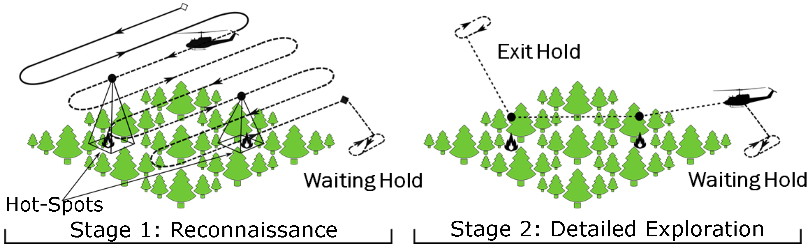
Figure 2.
Copterworks AF25B in RC Mode and unbox of Copterworks AF30.

Figure 3.
Avionics and component locations inside the helicopter.
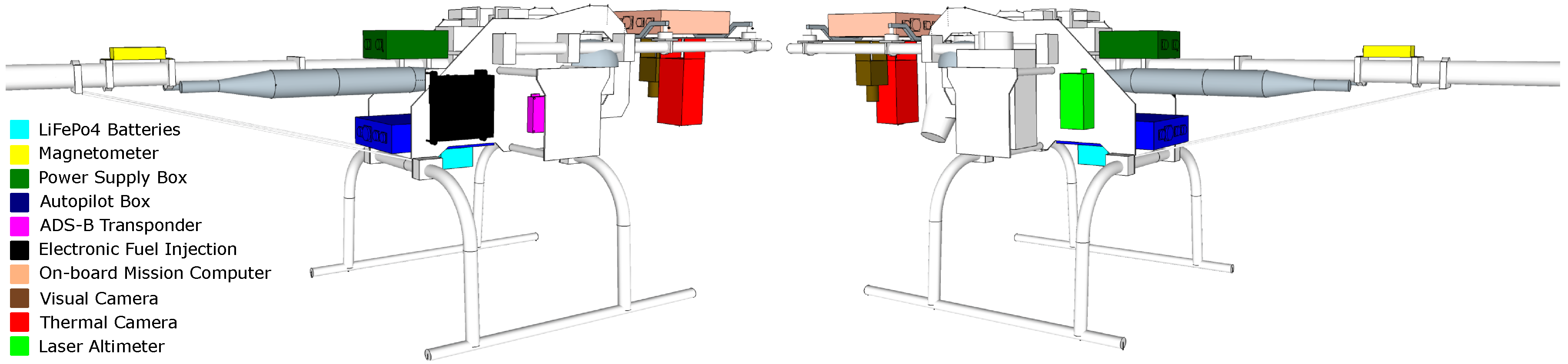
Figure 4.
Single Side Amplitude Accelerations in three axes. (a) Wire rope; (b) Silicon.
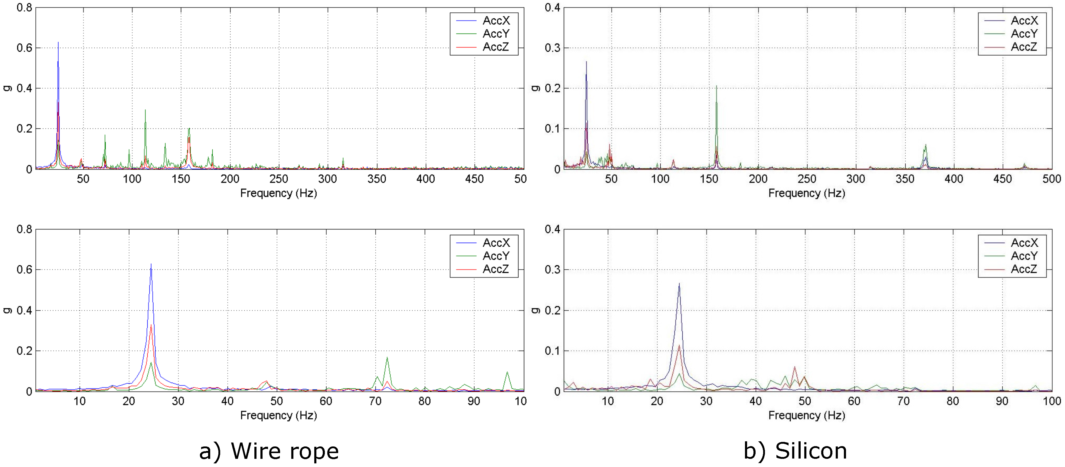
Figure 5.
Block Diagram of the Electronic Fuel Injection (EFI) added to the Helicopter.
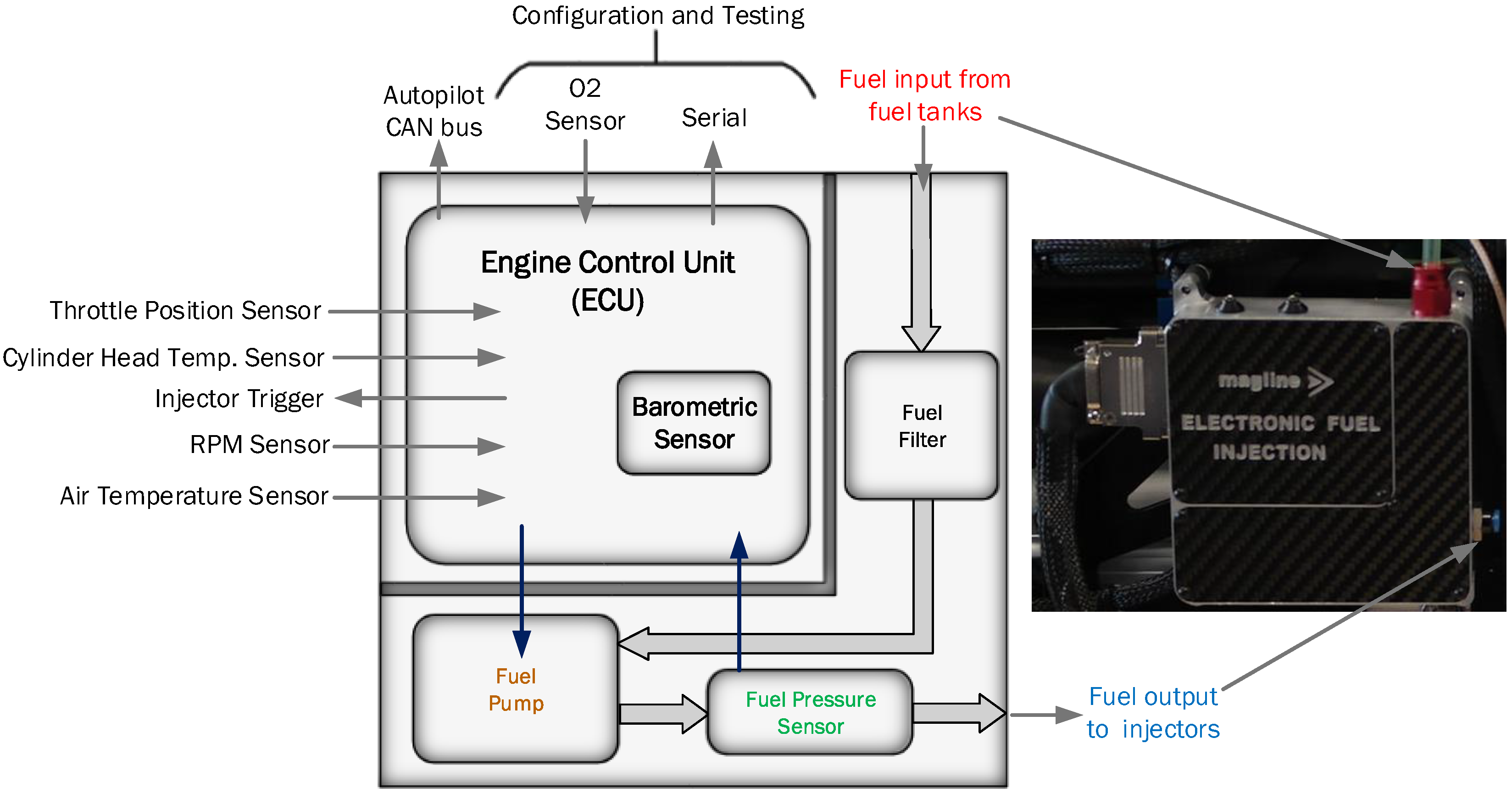
Figure 6.
Preliminary calibration table of Electronic Fuel Injection (EFI) before fine tuning.

Figure 7.
On the left is the fully integrated AF30 and on the right AF25B in radio control mode before the EFI validation test flight. Note the extra weight added on the AF25B model landing gear.
Figure 7.
On the left is the fully integrated AF30 and on the right AF25B in radio control mode before the EFI validation test flight. Note the extra weight added on the AF25B model landing gear.

Figure 8.
Engine Data provided by the AF30 EFI.

Figure 9.
Helicopter Power Supply System Block Diagram Design.
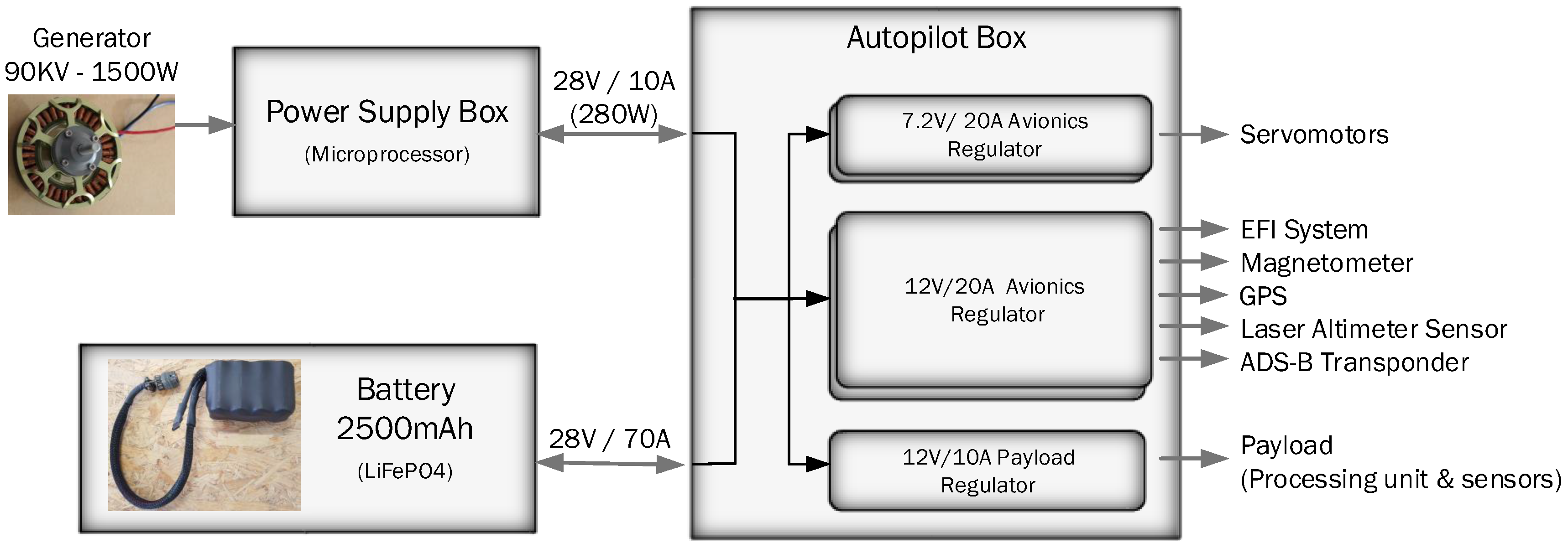
Figure 10.
Process of charging and discharging of batteries with the generator.

Figure 11.
Helicopter On-board Computation Box Block Diagram.
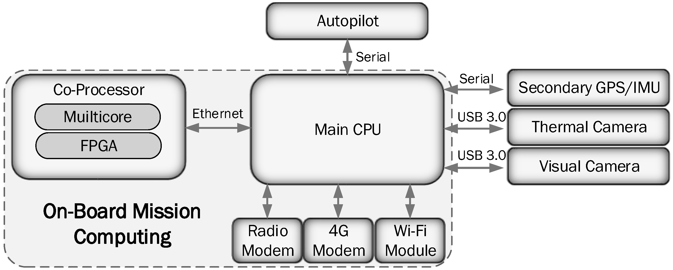
Figure 12.
Copterworks AF30 fully integrated and ready to fly.
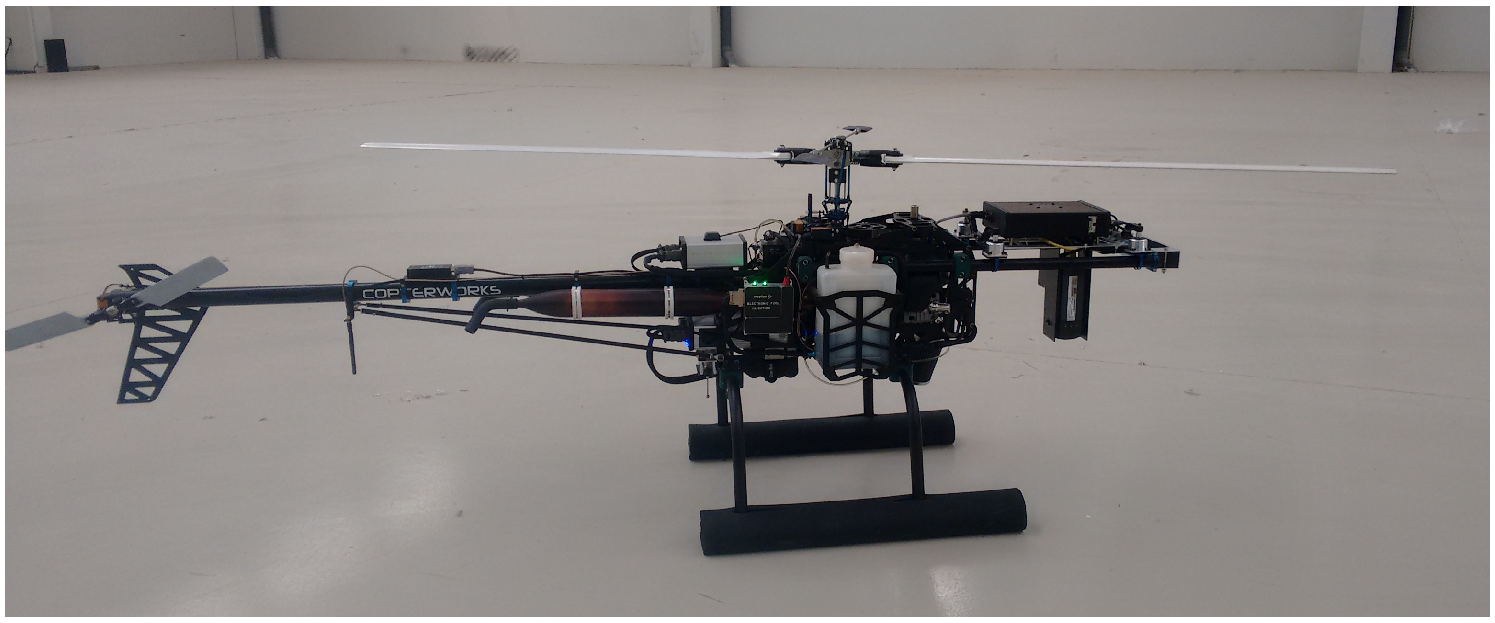
Figure 13.
Engine telemetry data of a flight test.

Figure 14.
Thermography test of the power supply system.

Table 1.
AF25B experiment fuel consumption result.
| Fuel Consumed | 1400 mL |
|---|---|
| Flight Time | 15 min |
| Fuel/h | 5600 mL/h |
| Fuel/min | 93.3 mL/min |
| mL·kg/h | 203.12 mL·kg/h |
Table 2.
Power consumption study in watts of all components integrated in the helicopter to dimension the power supply system
Table 2.
Power consumption study in watts of all components integrated in the helicopter to dimension the power supply system
| System | Nominal Power Consumption (W) | Max. Power Consumption (W) |
|---|---|---|
| Autopilot | 4 | 5 |
| Laser Altimeter | 4 | 5 |
| Magnetometer | 0.4 | 0.5 |
| GPS System | 2 | 2.5 |
| Transponder | 7 | 12 |
| EFI & CDI | 21 | 21 |
| Servomotors × 5 | 10.0 (5 × 2 W) | 100.0 (5 × 20 W) |
| Mission Payload | 75 | 120 |
| TOTAL | 123.4 | 266 |
Table 3.
Power consumed and energy required in each flight phase.
| Phase | Nominal Power Consumption (W) | Time (hours) | Consumed Energy (Wh) | Battery Capacity (Consumed Energy + 20% in Wh) |
|---|---|---|---|---|
| Checking | 48.40 | 0.25 | 12.10 | 14.52 |
| Mission | 123.40 | 1.00 | 123.40 | 148.08 |
| Emergency | 48.40 | 0.50 | 24.20 | 29.04 |
© 2017 by the authors. Licensee MDPI, Basel, Switzerland. This article is an open access article distributed under the terms and conditions of the Creative Commons Attribution (CC BY) license (http://creativecommons.org/licenses/by/4.0/).
Share and Cite
MDPI and ACS Style
Royo, P.; Pastor, E.; Barrado, C.; Cuadrado, R.; Barrao, F.; Garcia, A. Hardware Design of a Small UAS Helicopter for Remote Sensing Operations. Drones 2017, 1, 3. https://doi.org/10.3390/drones1010003
AMA Style
Royo P, Pastor E, Barrado C, Cuadrado R, Barrao F, Garcia A. Hardware Design of a Small UAS Helicopter for Remote Sensing Operations. Drones. 2017; 1(1):3. https://doi.org/10.3390/drones1010003
Chicago/Turabian StyleRoyo, Pablo, Enric Pastor, Cristina Barrado, Raul Cuadrado, Felix Barrao, and Antonio Garcia. 2017. "Hardware Design of a Small UAS Helicopter for Remote Sensing Operations" Drones 1, no. 1: 3. https://doi.org/10.3390/drones1010003