“7M”Advantage of Abrasive Waterjet for Machining Advanced Materials


OMAX Corporation, 21409 72nd Avenue South, Kent, WA 98032, USA
J. Manuf. Mater. Process. 2017, 1(1), 11; https://doi.org/10.3390/jmmp1010011
Submission received: 2 August 2017
/
Revised: 27 August 2017
/
Accepted: 1 September 2017
/
Published: 13 September 2017
Abstract
:Under the support of an SBIR Phase II/IIB grant from the National Science Foundation, OMAX has developed and commercialized micro abrasive (µAWJ), culminating A MicroMAX® JetMachining® Center technology for meso-micro machining. AWJ inherently possesses technological and manufacturing merits unmatched by most machine tools. With the commercialization of µAWJ technology, waterjet is now fully capable of multi-mode machining most materials from macro to micro scales (the 7M advantage). Novel accessories and software facilitate machining precision 2D and 3D parts with a wide range of part size and thickness. The versatile waterjet is particularly advantageous for machining difficult and delicate materials, such as alloys, hardened steel, composites, and laminates. One unique capability is machining composites and nanomaterials comprised of metals (reflective and conductive), non-metals (non-conductive), and anything in between. The 7M advantage of waterjet has been taking advantage by machining sample parts made of a variety of advanced materials that are difficult, or even impossible, to machine otherwise.
1. Introduction
The demand for advanced materials including composites, titanium, and various alloys for aerospace, industrial, and military applications has been skyrocketing in the past decade, and the same trend will continue at least for the next two decades. The use of composites and alloys began with building military aircrafts to boost performance. Now, commercial aerospace, energy, and the microelectronics industries are driving double-digit growth in composites [1,2]. In particular, there has been a paradigm shift in aircraft design at the Boeing and Airbus, with composites now specified for primary structures. In order to develop lighter, more efficient, and more durable planes, Airbus is increasingly applying engineered composite material to aircraft designs. The airframe of the new A350 XWB (“extra Wide Body”) aircraft is more than 50 percent composite materials by weight [3]. The composites market segment, with aerospace as the primary driver, is projecting a growth rate of 19% compound annual growth rate (CAGR) for the next decade.
Conventional machine tools such as routers, saws, and lathes are often not suitable for machining composites and high-strength alloys. It has been demonstrated that mechanical routers induce considerable tear and fray on nonmetallic honeycomb materials and most conventional machine cutting tools have difficulty with high-strength alloys [4,5].
Although advances in machine tool technology are developing at a rapid pace, machining composites and alloys still present considerable challenges. Machining and cutting options include laser, electronic discharge machining (EDM), ion beam/electron beam cutting, and microwave cutting. All have certain advantages as well as drawbacks. Lasers offer advantages such as accuracy and speed, but they cannot cut reflective materials such as copper. They are often limited to cutting thin materials and can negatively impact materials by creating heat-affected zones (HAZ) near the cut line. For example, the intense heat generated by CO2 lasers often results in the discoloration and slag formation from melted materials. In extreme cases, warping and other destructive effects are observed [6,7]. Advances in modern solid-state lasers, including femtosecond lasers pulsed at high frequencies have been applied successfully to minimize heat-induced damage with the sacrifice of cutting speed.
EDM offers excellent accuracy and edge quality but it is limited to cutting conductive materials. Materials common to the aerospace industry, such as fiberglass, carbon fiber, and ceramic matrix composites cannot use this cutting technology. The EDM cutting process, like lasers, can create HAZ near the cutting area. HAZ can be mitigated by process modification at the cost of speed.
With the ever increasing usage of composites for aerospace, industrial, military, and biomedical applications, there is considerable demand for an alternate machine tool that is non-damaging, cost-effective, versatile, and environmentally, and user friendly for machining a variety of composites.
In addition to composites and alloys, nanomaterials are another class of material gaining momentum in manufacturing technology. Nanotechnology is expected to mature for commercialization in five to ten years. It has been demonstrated that nanotechnology is capable of producing materials with properties ranging from metals to non-metals [8]. Such nanomaterials are considerably stronger and tougher than composites or metal alloys. Properties like conductivity and reflectivity could vary within nanomaterials as well. Machining such nanomaterials would present tremendous challenges to established machine tools, particularly for those that are material selective.
With successful development and commercialization of micro abrasive waterjet (µAWJ) technology, waterjet has emerged as a versatile tool capable of machining most materials from macro to microscales, namely the 7M advantage. AWJs possess several inherent merits that are unmatchable by most other machine tools [4]. For machining a variety of composites without internal piercing, AWJs have been used widely for machining composites for aerospace and industrial applications [9,10]. Internal features have proven a challenge to traditional AWJ as piercing results in stagnating pressure inside blind holes created by the jet. Piercing damage results when the stagnating pressure exceeds the ultimate strength of delicate materials. For example, composites and many brittle materials have inherently weak tensile strength, whereas laminates often possess weak adhesive strength between layers [4].
One of the remedies to minimize the above damage includes pre-drilling a starting hole with a drill attachment to alleviate the static pressure buildup inside of blind holes. This solution was limited to thin and relatively soft materials. For small holes, the drill bits may not be sufficiently stiff to pierce straight holes. For very tough and strong materials, such as silicon carbide ceramic matrix composites (SiC CMCs), the drill head will experience considerable wear. In fact, SiC CMCs are notoriously known to be a frequent tool breaker.
Novel AWJ processes were subsequently developed to mitigate piercing damage. For example, both the liquefied nitrogen-based abrasive cryogenic jet (ACJ) and the patented super-heated or flash abrasive waterjet (FAWJ) were demonstrated to minimize the piercing damage as most of the working fluids evaporated upon exiting the mixing tube [11,12]. As such, the stagnating pressure inside of the blind hole was minimized. Unfortunately, both the ACJ and the FAWJ were not practical for industrial applications due to their severe operating environments. Based on the experience gained from studying the ACJ and the FAWJ, however, it was confirmed that the buildup of stagnation is the root cause for AWJ piercing damage. Novel processes were successfully developed to minimize the buildup of stagnation pressure during the AWJ piercing delicate materials. Such processes combined with low-pressure piercing were routinely used to mitigate AWJ piercing damage to composites, laminates, and various brittle materials.
In this paper, the “7M” advantage and the versatility of AWJ is demonstrated by presenting various AWJ-machined 2D and 3D parts. Many of the parts were made of advanced materials with a wide range of material properties and types [13]. For parts made of delicate materials, novel piercing processes designed to minimize the stagnating pressure inside blind holes were applied to mitigate the AWJ-piercing damage. 3D parts were either machined with multiple machining steps or with accessories designed for AWJ 3D machining. In certain cases, post shaping or forming was used to reshape 2D parts into 3D parts.
2. Facilities and Devices
2.1. JetMachining Centers
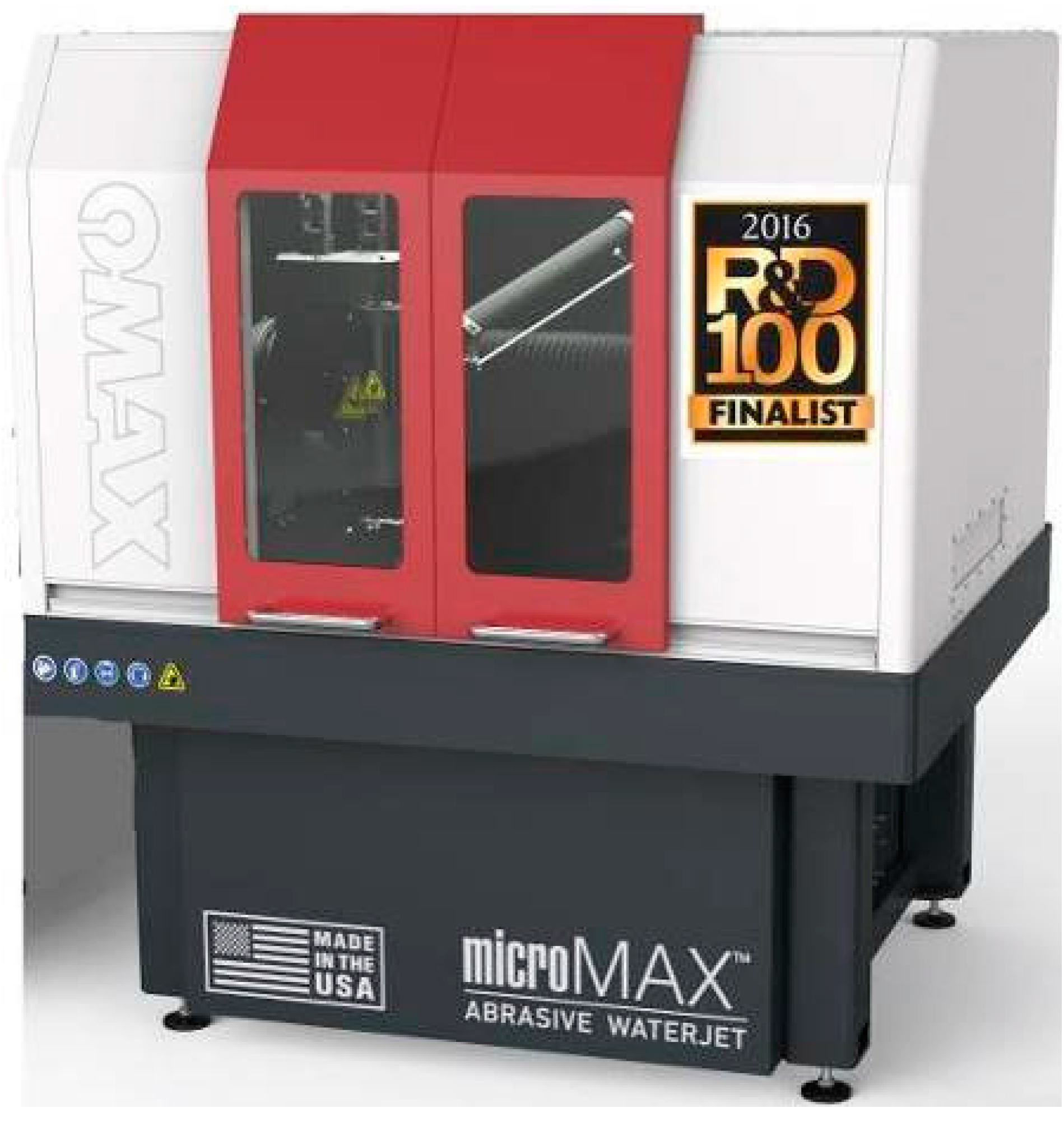
AWJ machining was conducted in the R&D and Demonstration Laboratories of OMAX Corporation in Kent, WA, USA. The Laboratories are equipped with a MicroMAX (OMAX Corporation, Kent, WA, USA) and four JetMachining Centers (JMCs). These JMCs are equipped with accessories such as the Tilt-A-Jet (TAJ), A-Jet, and the Rotary Axis for 2D and 3D machining. Figure 1 illustrates a photograph of a MicroMAX that was named a finalist of the 2016 R&D 100 Awards. The MicroMAX is designed for precision meso-micro machining for most materials. It has a work envelope of 24” × 24” (610 mm × 610 mm). It has a position accuracy of better than 0.0006” (15 µm) (https://www.omax.com/omax-waterjet/micromax). The cutting platform is vibration isolated to minimize external disturbance while cutting.
Figure 2 illustrates a photograph of the Model 160X JMC. It has a work envelope of 8.1 m × 4.0 m. (https://www.omax.com/omax-waterjet/160x-series). There are two traverse systems that can be used simultaneously and independently to machine larger and multiple parts.
2.2. AWJ Nozzles
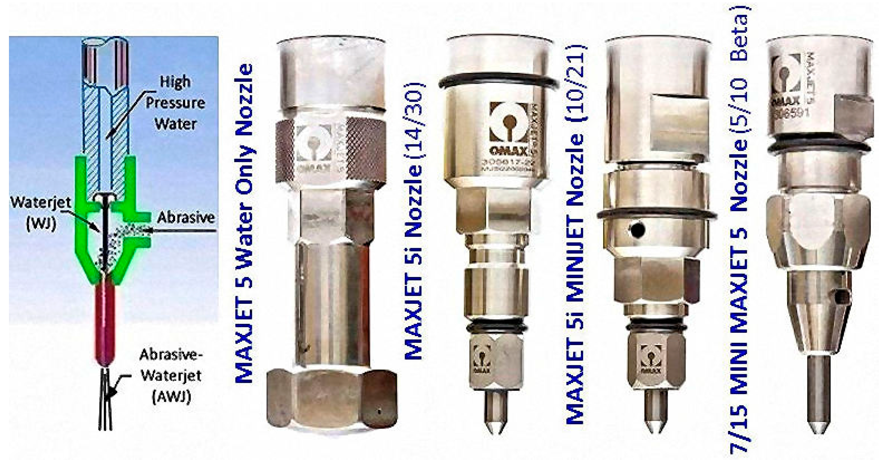
There are several production nozzles designed for machining parts with a wide range of part size and thickness, as illustrated in Figure 3. The smallest production nozzle is a 7/15 nozzle consisting of a 0.007” (0.18 mm) ID orifice and a 0.015” (0.38 mm) ID mixing tube. A 5/10 beta nozzle is also available for machining even finer features.
2.3. Vacuum Assist
For piercing delicate materials, the pressure was set to low-pressure mode to mitigate the piercing damage. The Venturi vacuum induced by the jet pump effect of the waterjet is not adequate to entrain all of the abrasives fed from the hopper. Accumulation of abrasive inside the mixing chamber would lead to nozzle clogging. Special nozzles were equipped with a second port opposite to the abrasive feed port for vacuum assist and water flushing were used to prevent nozzle clogging. The vacuum-assist mode was activated whenever the waterjet was set to low-pressure operation to remove the excessive abrasives accumulated in the mixing chamber. The vacuum-assist mode was deactivated as soon as the hole was pierced through and high-pressure cutting resumed.
2.4. Accessories for 3D Machining
AWJ is amenable to 3D machining but must be carried out with discretion. One of the properties of AWJ is that the spent abrasives, if not “tamed” or captured, still possess considerable residual cutting power that could induce damage to other parts of the workpiece and pose a potential hazard to the operators. In other words, AWJ is not inherently suitable for 3D machining by simply mounting the nozzle on a multi-axis manipulator. Because the simplest and most effective means to dissipate the residual energy of spent abrasives is to let the spent abrasives shoot generally downward into a column of still water, most AWJ systems are built on top of a water tank that also serves to support the traversing mechanism. Such AWJ systems that are operating within the limitations of safety are mainly designed for 2D machining.
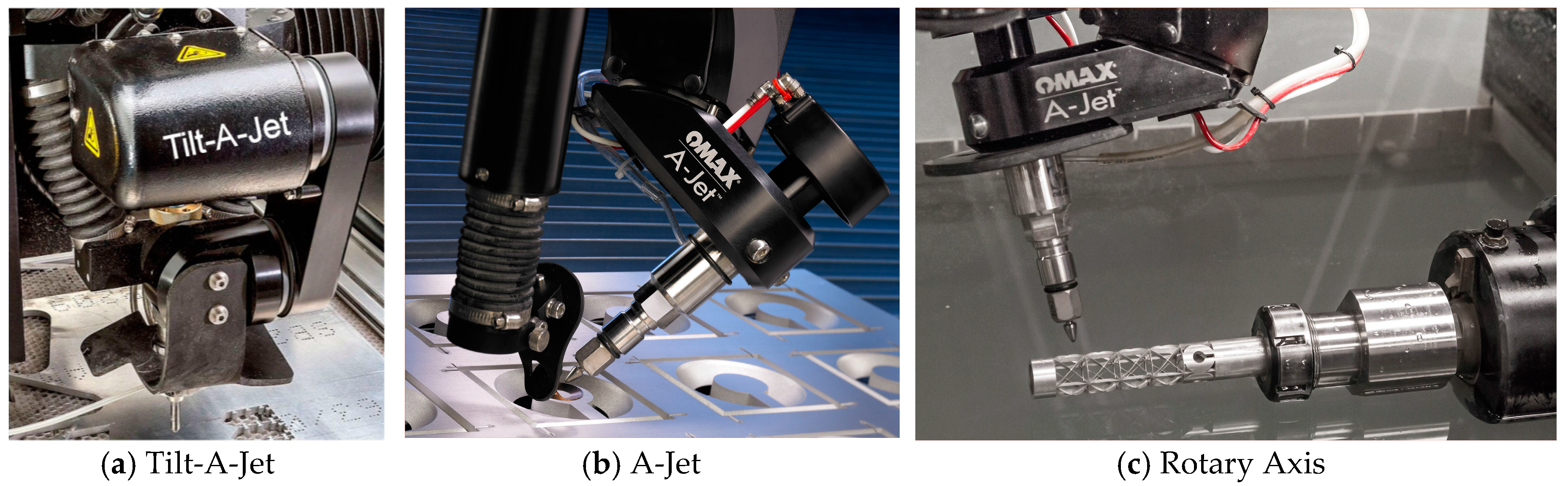
Novel multi-axis accessories have been developed to facilitate AWJ 3D machining while ensuring the operation safety, by either manipulating the workpiece or incorporating to the 2D AWJ platform. Figure 4 illustrates three typical accessories including:
- A Tilt-A-Jet (TAJ) is for compensating the natural taper on AWJ-cut edges resulting from the spread of the jet after it exits the nozzle (https://www.omax.com/accessories/tilt-a-jet). Figure 4b illustrates a photograph of the TAJ. It is a 3-axis device with a programmable tilt up to ±9° for the maximum tilt angle around the vertical axis. During machining, the TAJ dynamically tilts the nozzle along the tool path to eliminate the taper on the part automatically, while leaving twice the taper on the scrap.
- An A-Jet (articulate jet) is a software-controlled multi-axis cutting head that greatly expands the versatility of the OMAX JetMachining Center. With a cutting range from 0° to 60°, the A-Jet can easily cut beveled edges, angled sides, and countersinks (https://www.omax.com/accessories/a-jet).
- A submersible Rotary Axis is for machining 3D features in tube, pipe, and bar stock (https://www.omax.com/accessories/rotary-axis).
By combining the operations of these accessories (Figure 4c), AWJ is capable of cutting 6-axis paths to create complex 3D shapes.
2.5. Machineability and Pierceability
In the cutting model, each material is assigned with a machineability index, M. The higher the value of M, the faster it can be cut with the AWJ for the same cutting parameters and edge quality [14]. For example, M = 215, 81, and 108 for 2024 aluminum, 304 stainless steel, and 6Al 4V titanium, respectively. In other words, AWJ cuts aluminum about nearly three times faster than stainless steel, whereas it cuts titanium 1/3 faster than stainless steel. For AWJ drilling, the cutting model assigns a pierceability for each of the materials. For ductile materials, the pierceability is often proportional to the machineability. There is however exceptions for other materials and piercing tests will be conducted to determine their pierceability.
3. Samples of AWJ-Machined Parts
Samples of AWJ-machined parts made from a variety of advanced materials including hardened steel, alloys, composites, laminates, and simulated nanomaterials with large gradients of material properties are presented to demonstrate the versatility of waterjet technology.
3.1. Material Independence
Abrasive waterjet cutting is performed through erosion by high-speed abrasives. Such an erosion mode of cutting is material independent. The demonstration of the material independence of AWJ was made by cutting a wide range of materials. Figure 5 illustrates a collection of AWJ-machined 2D and 3D parts made from a variety of materials including aluminum, titanium, stainless steel, copper, brass, carbon fiber, G-10 glass-epoxy composite, fiberglass, polycarbonate, ultra-high-molecular-weight polyethylene (UHMW), polyether ether ketone (PEEK), and others. The four sides forming the interlocking frame shown in the figure was machined from glass. Note that waterjet exerts a negligible side force onto the workpiece. In the absence of HAZ, large-aspect-ratio slots with very thin webs in between can be readily machined with the waterjet on thin materials. For example, the titanium butterfly shown in Figure 5 (on the right and a little half way down) presented considerable challenge to CO2 laser as the heat generated by the laser melted the thin webs between slots [6]. Some of the above materials combined with demanding part geometries are difficult or even impossible to machine with other tools.
For machining composites and brittle materials with weak tensile strength and laminates with weak adhesive strength between layers, traditional AWJ used to be problematic as large stagnating pressure developed inside blind holes (before breakthrough) during the initial piercing operation. Piercing damage in terms of cracking and delamination took place whenever the stagnating pressure exceeded the tensile or adhesive strength of the above materials [4]. Under such a condition, the delamination is initiated by the shock wave impact of the AWJ during piercing the blind hole. The crack tips initiated by the shock wave impact are then propagated outward as the slurry penetrates into the crack, promoting water-wedging and abrasive embedment [15]. Considerable R&D efforts were devoted to mitigate AWJ-piercing damage. Abrasive cryogenic jet (ACJ) and super-heated flash abrasive waterjet (FAWJ) were utilized to mitigate AWJ-piercing damage [11,12]. The operating conditions of the two processes were unfortunately too demanding and severe that they were not suitable for industrial applications. The results of the R&D have however confirmed the causes of AWJ-piercing damage, as described above. Based on the findings of the R&D using the ACJ and FAWJ, two novel processes were developed for mitigating AWJ piercing damage on delicate materials. Turbo Piercer and Mini Piercer were developed for machining relatively large and miniature internal features, respectively. Turbo Piercer applies a low pressure to force feed rather than gravity feed the abrasive. The pressurized feeding of the abrasives facilitates the tuning of the AWJ to reduce the stagnating pressure inside the blind hole such that the tensile strength of delicate materials is not exceeded. Figure 6 illustrates several AWJ-machined parts. Figure 6a is a photograph of an AWJ-pierced hole without the use of the Turbo Piercer. Multiple delaminations along the hole wall are evident. In Figure 6b, the large part was cut from G-10 glass epoxy with the Turbo Piercer. The rest of the four parts were cut with the Min Piercer from silicon wafer, (top left), glass (top right), fiberglass (lower left), and aluminum laminate (lower right). They consisted of internal features including a logo and several through holes. No delamination is observed along the hole wall. Note that the peak tensile stress of G-10 is around 200 to 300 MPa. It is necessary to tune the AWJ to ensure that the stagnating pressure is below 200 MPa [16]. Optimizing the pressure tuning function of the Turbo Piercer is necessary to maximize the cutting power.
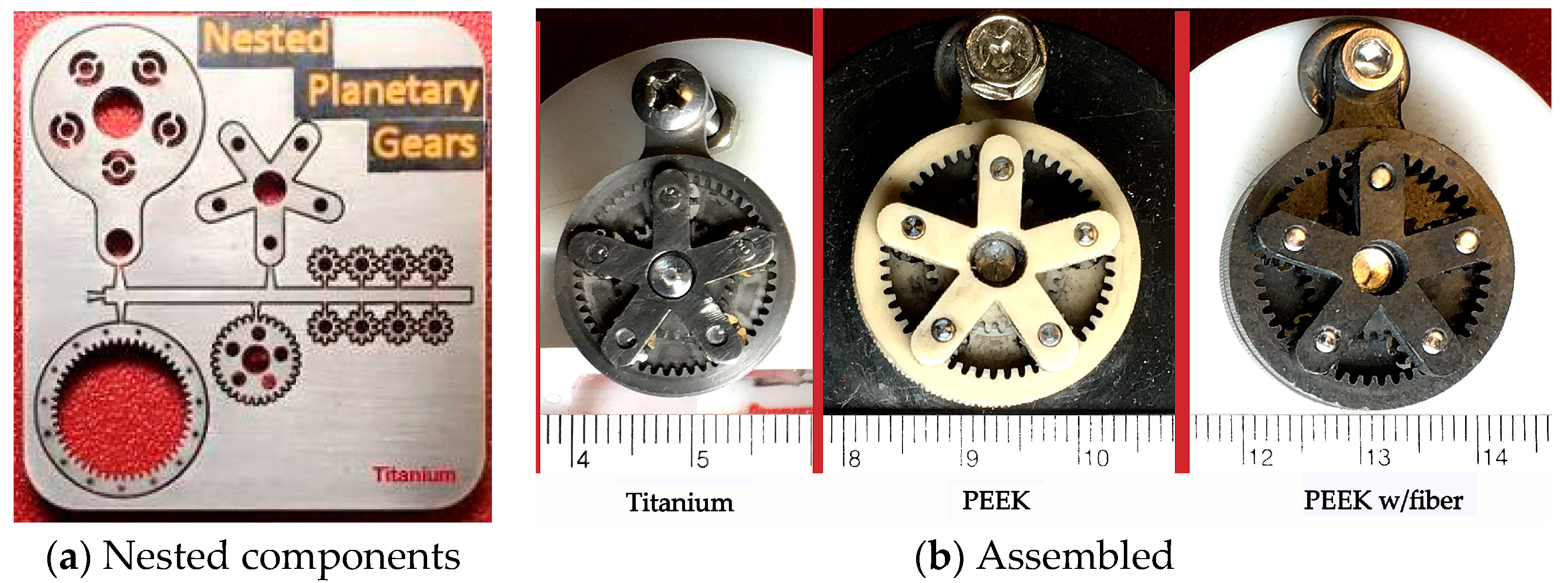
Figure 7 illustrates photographs of three sets of AWJ-machined miniature planetary gears made from titanium and PEEK without and with fiber reinforcement. Figure 6a illustrates the components of the gears closely nested on the workpieces. Each component remained attached to the workpiece via a thin tab. The components were then assembled without going through the secondary process. All of them driven by battery powered micro motors were operating smoothly.
3.2. Part Size and Thickness
As illustrated in Figure 2, several waterjet nozzles are available for cutting parts made of different materials and with various sizes and thicknesses. Nonstandard orifice and mixing tube configuration other than the ones shown in the figure can also be used to optimize their cutting performance. In addition, several abrasives, such as aluminum oxide, steel shot, garnet, and walnut, can be selected to optimize the cutting performance. For example, the MAXMET 5i nozzle with the use of 80 or 50 mesh garnet can be used for cutting metals and alloys with a thickness of 20 cm or larger. On the other hand, the 7/15 or 5/10 MAXJET5 nozzle using abrasives as fine as 320 mesh was optimized for machining miniature features on thin materials; the finer the abrasive the better the edge quality is achieved.
Figure 8 illustrates two AWJ-machined gears of vastly different size. The large gear corresponds to an AWJ-cut segment of a 100 mm thick Bisalloy 1.5 m OD wind turbine gear as a replacement of a damaged segment. The AWJ-cut replacement segment is placed directly on top of the gear under repair. The severely damaged segment is shown in the lower-left corner of the figure. Superimposed on the photograph is a 3.5 mm OD and 0.5 mm thick titanium gear that corresponds to one of the smallest of the miniature planetary gear set, as illustrated in Figure 7a. When displayed at the same scale, the planetary gear merely showed up as a speckle that was barely visible as the diameter and thickness ratios of the two gears were 428 and 200, respectively. There is no other single-tool machine capable of machining parts with such vastly different scales.
3.3. Delicate and Difficult Materials
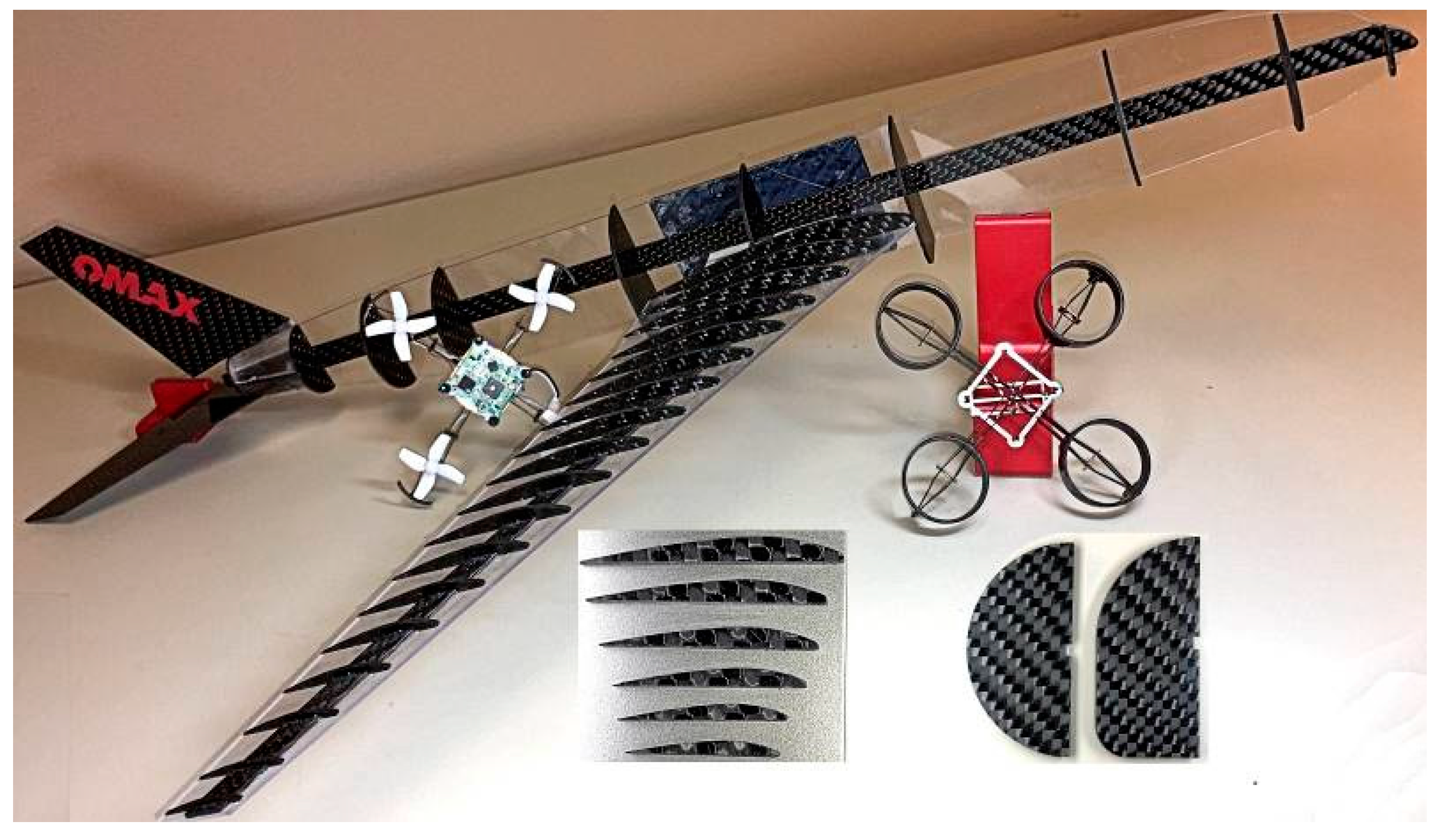
Carbon fiber has been one of the most popular composite materials for industrial, military, aerospace, and biomedical applications. Considerable efforts have been made to apply waterjet to machine 2D and 3D demonstration parts made from carbon fiber. Since certain carbon fiber is brittle, it is important to use low-pressure piercing to mitigate AWJ piercing damage in the form of chipping and cracking. Figure 9 illustrates a carbon fiber B777 model aircraft and two quadrones. Several cross-sectional profiles along the wing and the nacelle are also shown in the figure. Inlaying letters or logo on the vertical stabilizer is simple and effortless. The quadrone on the right with a full diffuser was too heavy to fly. In order to reduce the weight, only 1/6 of the diffuser perimeter was retained while significantly shortening its length. As a result, the lightweighted quadrone on the left was fully functional.
The strength and durability of carbon fiber has been taken advantage of for fabricating musical instruments that are traditionally made from wood. For example, carbon fiber has been applied to fabricate stringed instruments with a superior quality (http://stringsmagazine.com/a-buyers-guide-to-carbon-fiber-instruments/). Many of these instruments are presently handmade. Semi automating the fabrication process with waterjet would reduce the manufacturing cost. Components of a ukulele made of carbon fiber sheets were machined with a JMC. The ukulele, illustrated in Figure 10, was subsequently assembled. For violins or violas, the AWJ machined front faces can be formed precisely to their curved shape with a post thermally pressing process [17].
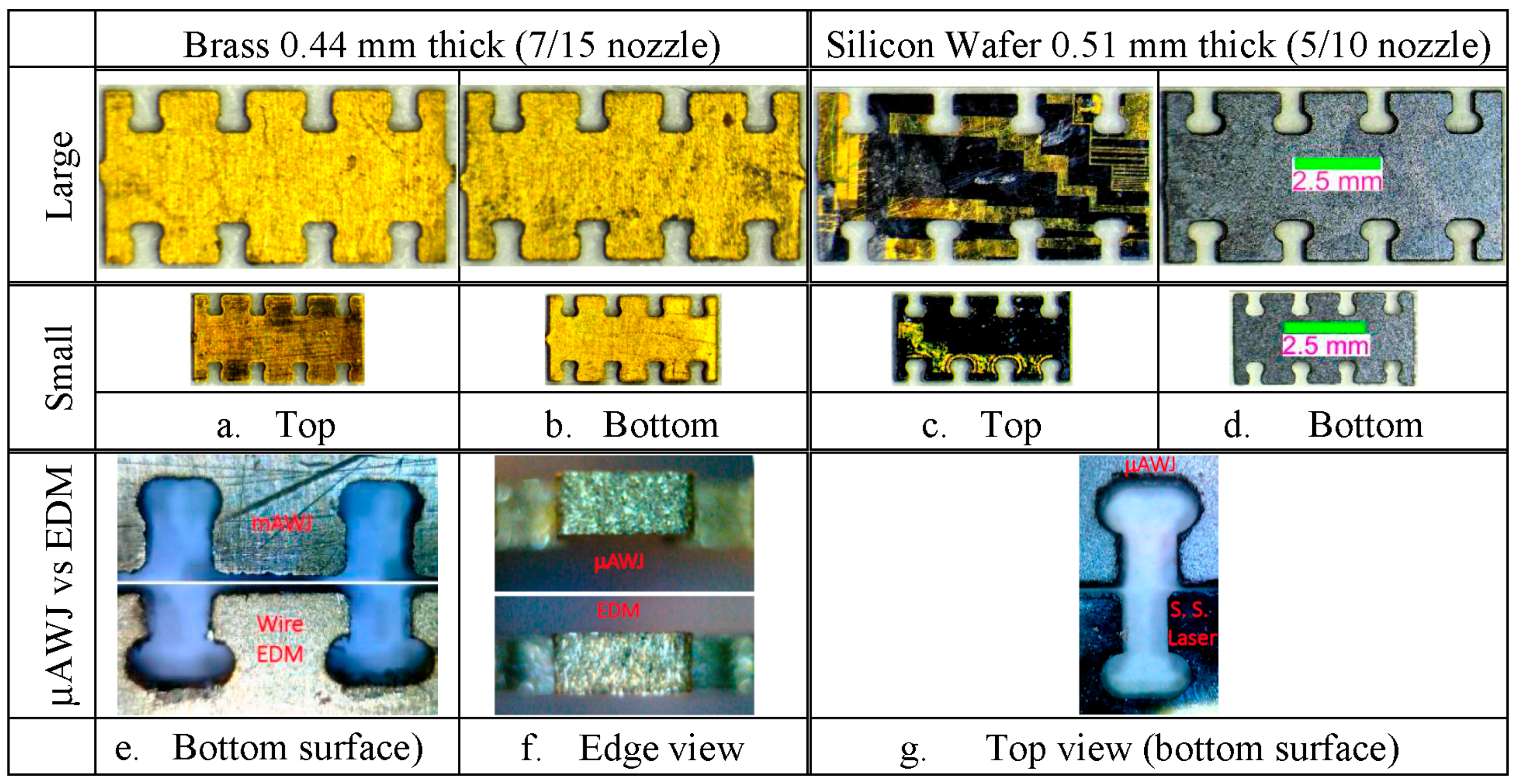
Miniature parts made from brass and silicon wafer were machined on the MicroMAX using the 7/15 and 5/10 nozzles. Figure 11 illustrates the micrographs of the large and small parts made of the two materials. The overall length and the diameter of the large were 7.5 mm and 0.38 mm, respectively. The dimensions of the small part were 0.67 time that of its larger counterpart. Note that the IDs of the mixing tubes for the two nozzles were 0.38 mm and 0.25 mm, respectively. In other words, the ID diameter was the same as the arc diameter of the large part. The minimum kerf width cut with a nozzle is typically 1.15 times the mixing tube diameter. Careful inspection of the parts revealed that the 7/15 nozzle failed to negotiate accurately the arc segments with 0.38 mm and 0.25 mm diameters (Figure 11a,b), whereas the 5/10 nozzle succeeded to do so for the segment with the 0.38 mm diameter (top half of Figure 11c,d). The 5/10 nozzle, on the other hand, had a similar problem negotiating the arc segments with 0.25 mm diameter as the minimum kerf width achievable by that nozzle was about 1.15 × 0.25 mm or 0.29 mm.
Cutting tests with wire EDM (Sodick, Model SL400G with a 0.15 mm wire, Sodick Corporation, Schaumburg, IL, USA) and a solid-state laser with a focal spot of about 20 µm (Oxford Lasers, Model A-532, Oxford Lasers, Inc., Shirley, MA, USA) were conducted to cut the two materials at the laboratory of Center of Bits and Atoms (CBA). Since EDM and lasers are material selective, wire EDM and the solid-state laser were used to machine the brass and silicon wafer parts, respectively. Comparison of the performance of the µAWJ with those of the wire EDM and the laser indicated that the wire EDM and the laser negotiated the 0.38 mm- and 0.25 mm-diameter arc segments well (Figure 11e,g), respectively.
Nanotechnology has been advancing steadily in the past several decades. Manufactured at the nanoscale level, some nanomaterials have achieved the dual properties of high strength and ductility [18], while others have unique electrical, magnetic, optical, and chemical properties. In some cases, anisotropic behavior for the above properties is observed in nanoparticles and materials. Nanocomposites incorporate nanoparticles to impart the above referenced properties on polymeric, ceramic, and metal materials. Other techniques include layering or depositing nano-particles on the surface of a substrate. While not known presently, HAZ created by other machine tool technologies may negatively impact the nanoparticle properties. AWJ technology may also offer versatility to machine nanocomposite materials where optical or electrical properties are present.
At present, large-size anisotropic nanomaterials for industrial or consumer applications are not available commercially. A 2.9-mm-thick stack of eight thin materials including titanium, float glass, G-10, aluminum, polycarbonate, stainless steel, carbon fiber, and copper was assembled to simulate the aspect of structural anisotropy rather than the nanoscale of nanomaterials. This stack consisting of metals (conductive and reflective), non-metals (nonconductive and brittle), and composites was difficult if not impossible to cut otherwise. It was machined successfully into an airfoil shape with the AWJ using the 5/10 nozzle with 240 mesh garnet [13].
3.4. Multimode Machining
Another advantage of waterjet is that only a single tool is qualified for multimode machining from parting, facing, trimming, drilling, slotting/grooving turning, beveling, and milling. Figure 12 illustrated a photograph of an AWJ-machined chess set and board. The 3D chess pieces consisting of rather complex 3D features were machined from aluminum round stock using both the Rotary Axis and A-Jet. Half of the chess set was painted black. Zoom-in photographs of chess pieces are also shown to reveal their geometrical details. The chessboard was fabricated by alternatingly inlaying AWJ-cut light and dark color granite blocks. Carbon fiber inlays were used as a part of the boarder.
3.5. Taper-Free Parts
Tilt-A-Jet cutting head was designed to mitigate edge taper induced by the spreading of the AWJ and the degradation of cutting power with the cutting depth. As a part of the cutting model, the TAJ controlled by the Intelli-MAX software suite is tilted dynamically while cutting the part. The TAJ removes the taper on the part while leaving twice the taper on the scrap. In order to verify the performance of the TAJ, a precision laser-based edge taper measurement device was developed [19]. Several precision parts that required nearly taper-free edges were machined on the MicroMAX equipped with the TAJ. The performance of these parts including interlocking gear sets and high-resolution nonlinear load cells with five orders of magnitude of force range was successfully verified [19,20,21]. The nonlinear load cell (US Patent #20150233440) has three configurations consisting of: (i) constant-width cantiliver flexures with moment compliant “19.1 mm diameter ring” connections; (ii) variable-width ring flexures; and (iii) steel-spring flexures. Figure 13 illustrates the photographs of two of the load cells. The pressure was set at 380 MPa. The AWJ nozzle consisted of a 0.18 mm ID orifice and a 0.38 mm ID mixing tube. Garnet of 220 mesh with a flow rate of 45 gm/min was used. Performance tests of the first two were conducted at MIT and the results agreed well with the theory [20]. One of the main reasons for the good agreement was attributed to the taper-free flexures that minimized deviation from the theoretical prediction.
3.6. AWJ Hole Drilling
The performance of AWJ and ACJ for drilling holes in delicate and difficult materials has been investigated [22]. It was demonstrated that the profiles of AWJ-drill holes in aluminum and glass could be normalized reasonably well, for a given pressure, by plotting l/lmax versus d/ln(t) where l and lmax are the distance along the axis of the hole and the maximum hole depth, respectively. The test results showed that h(l) is not a constant. Figure 14 illustrates the photographs of AWJ-drilled blind holes in glass and aluminum. The pressure used to drill holes in glass and aluminum was 344 and 240 MPa. Relatively low pressures were used to drill holes in the brittle glass material to mitigate internal cracking. The AWJ nozzle consisted of a 0.25-mm ID orifice 0.76-mm ID mixing tube with a 220 mesh garnet at 160 gm/min. For precision holes with large aspect ratios, particularly for delicate and difficult materials, waterjet could beneficially serve as a net-shape driller and a secondary process would be needed to finish the hole profile according to specifications.
3.7. Etching and Milling
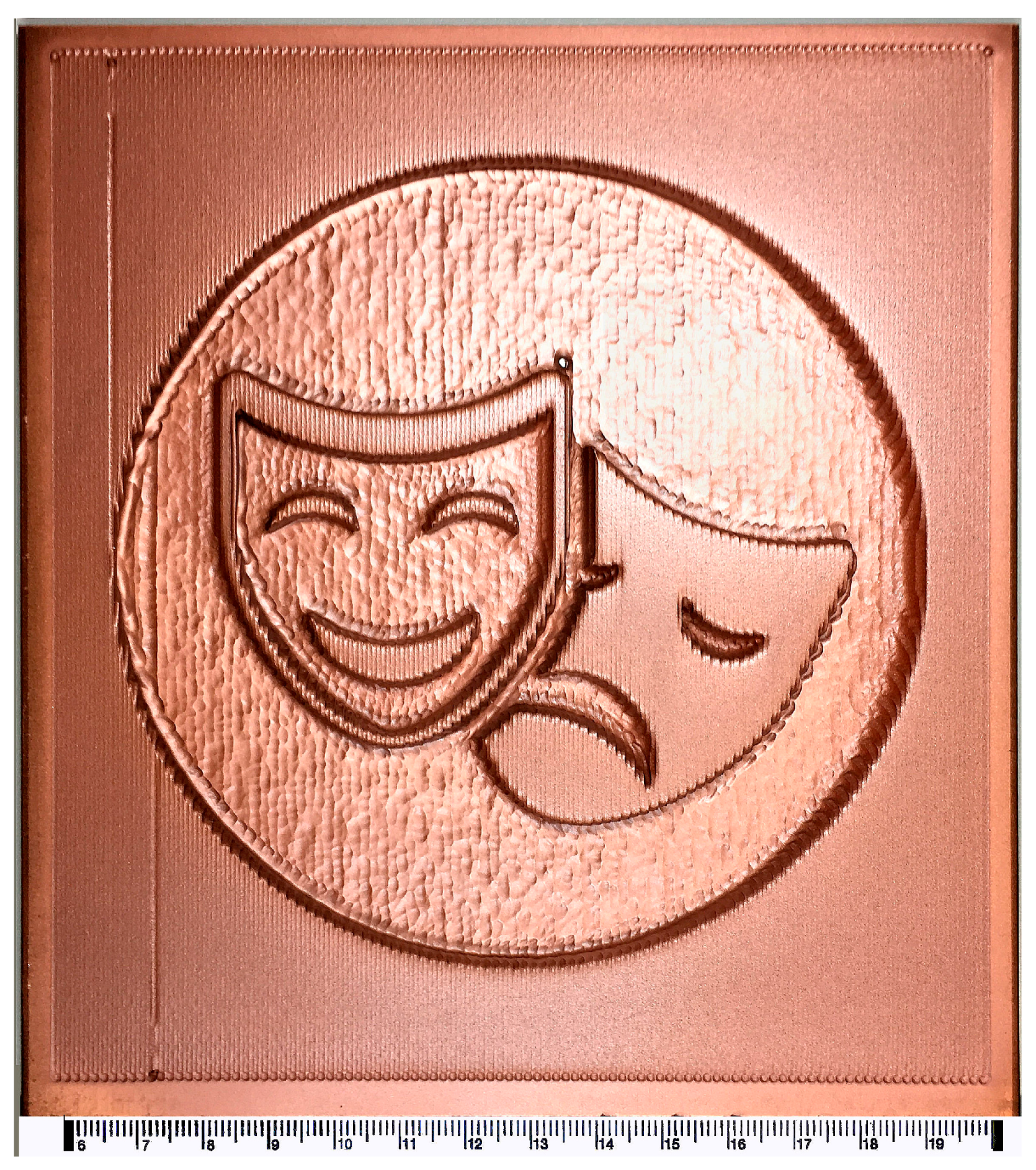
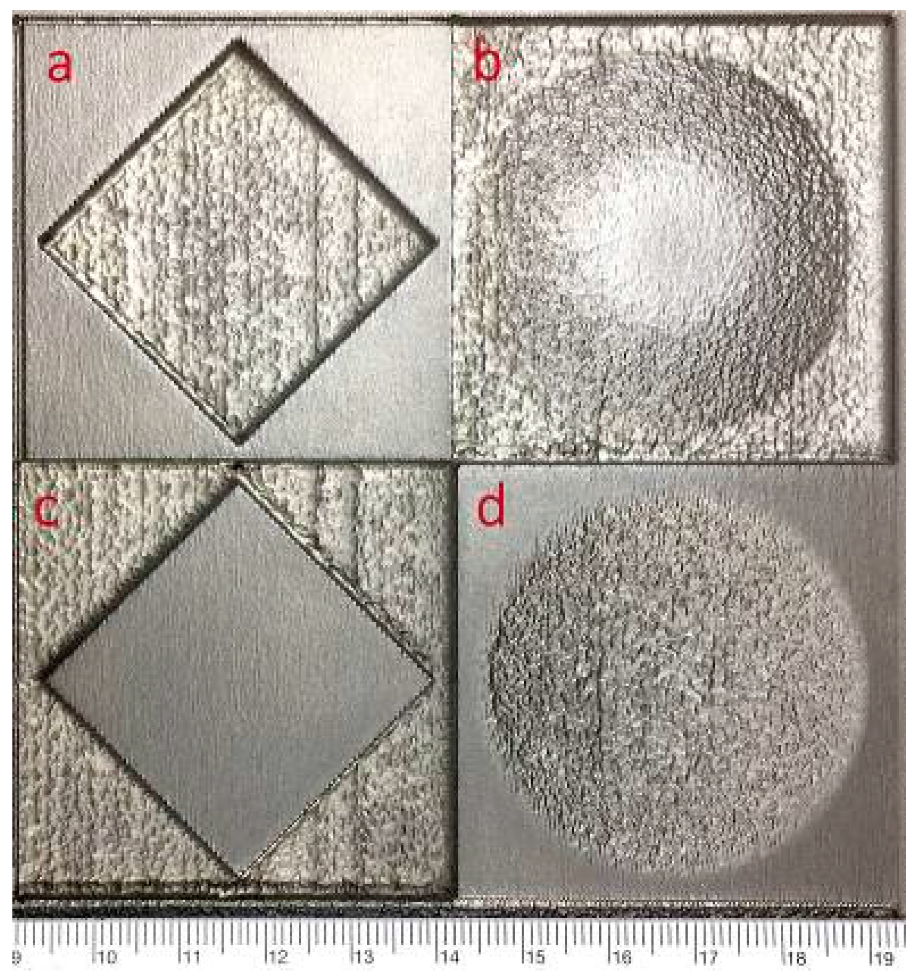
AWJ etching and milling are two of the multimode machining capabilities of waterjet. Etching and milling may be performed by using single- and multi-pass raster processes to produce flat or curved surfaces. The material removal per pass depends on the pressure, abrasive size and loading, and the speed of traverse. The faster the traversing speed, the smaller the materials per pass. The Intelli-Etch software controls the nozzle according to the designed tool path of the etch pattern for automated etching and milling. Figure 15 and Figure 16 illustrate AWJ-etched samples on a copper and stainless steel plates, respectively. The etched surface in Figure 15 is flat, whereas those on Figure 16 consist of flat (a,c), convex (b), and concave (d) surfaces, respectively. The two parts shown in Figure 15 and Figure 16 were machined in a single pass by an AWJ operating at 138 MPa, and with relatively course abrasive (80 mesh). The nozzle consisted of a 0.35-mm ID orifice and a 0.76-mm ID mixing tube. A garnet of 80 mesh at a flow rate of 0.34 kg/min was used. The pressure was set at 344 MPa. The nozzle etched at a relatively slow speed of 0.013 m/s to etch the part in a single pass. The surface roughness of the etched surface was also quite large as can be observed from Figure 15 and Figure 16.
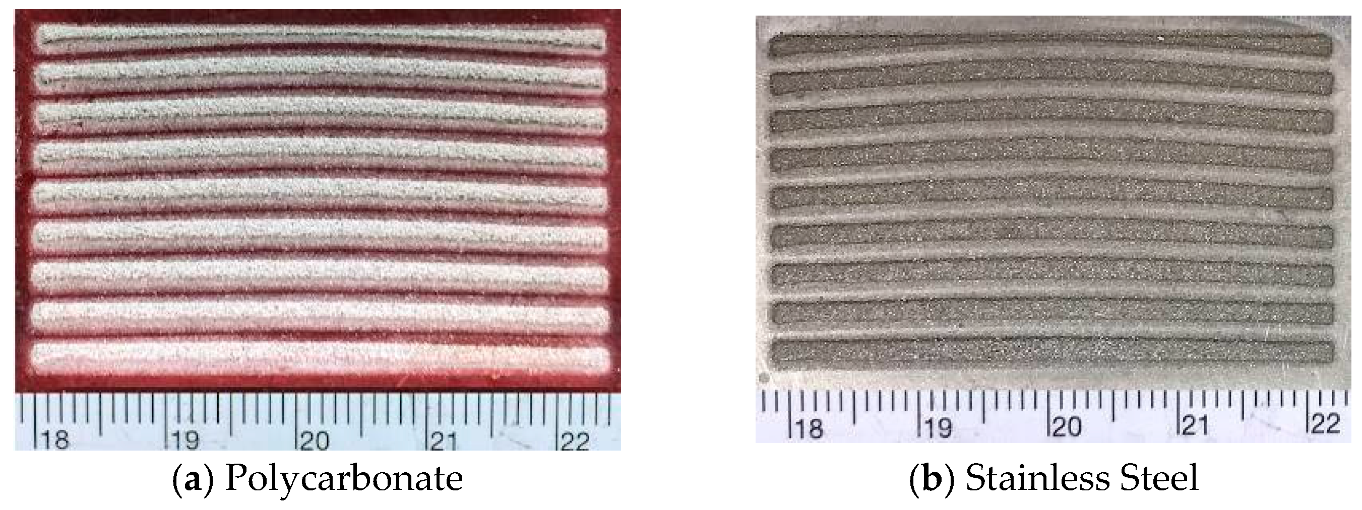
Etching was performed on polycarbonate and stainless steel discs with a diameter of 10 cm. The discs were mounted on an electric router as a part of a dual-disc anemometer (DDA) [23,24]. The discs were rotating at 10,000 rpm. The linear speed at the radius of 5 cm is therefore 31 m/s. The nozzle consisted of a 0.25 mm ID diamond orifice and a 0.53 mm ID mixing tube. The pressure and the abrasive flow rate were 240 MPa and 0.16 kg/min, respectively. The workpieces were covered with a steel mask consisting of four sets of slots. The waterjet-only-jet and AWJ were used for etching the polycarbonate and stainless steel discs, respectively. Milling was conducted by traversing the nozzle multiple times in the radial direction. Figure 17 illustrates the two sets of the grooves etched on the two discs. At the high rotating speed, the webs between slots on the relatively thin mask were distorted in the presence of the centrifugal force. Such distortions were also observed on the groove patterns. Note that the etched surfaces were considerably smoother than those observed in Figure 15 and Figure 16.
Near-net-shape of spherical surfaces were etched on float glass and aluminum nitride (AlN). The blanks were mounted on a platform rotating at 10,000 rpm. An abrasive slurry jet (ASJ), operating at 10 ksi (69 MPa) with 400 mesh garnet (for the glass), and 400 mesh garnet and aluminum oxide mixture (for the AlN) was used to etch/mill the parts [25]. The ASJ nozzle has a 0.25-mm ID orifice. Etching/milling were performed with the ASJ nozzle moving in and out along the radial direction in a zig-zag pattern. The nozzle traversing speed varied as a function of the radial position in order to form either a concave or a convex surface. Figure 18 illustrates photographs of the two parts. It is evident that the fast rotating speed of the workpiece and the reduction in the pressure and abrasive size contributed to the increase in the smoothness of the etched surfaces.
Figure 19 illustrates a photograph of AWJ-etched shallow pockets on a 177-mm diameter thin glass 5 mm thick. The depth of the pockets is 2.5 mm. Etching was conducted on a rotating table with the workpiece mounted on about 0.5 m from the center of the table. The rotating speed at the center of the workpiece was 8.5 m/s. The workpiece was covered with a mask on which the pocket pattern was cut out. The pressure was 170 MPa. The nozzle consisted of a 0.18 mm orifice and a 1.8 mm ID mixing tube. 220-mesh garnet at a flow rate of 0.9 kg/m was used. Milling was conducted at a large standoff distance of 0.25 m.
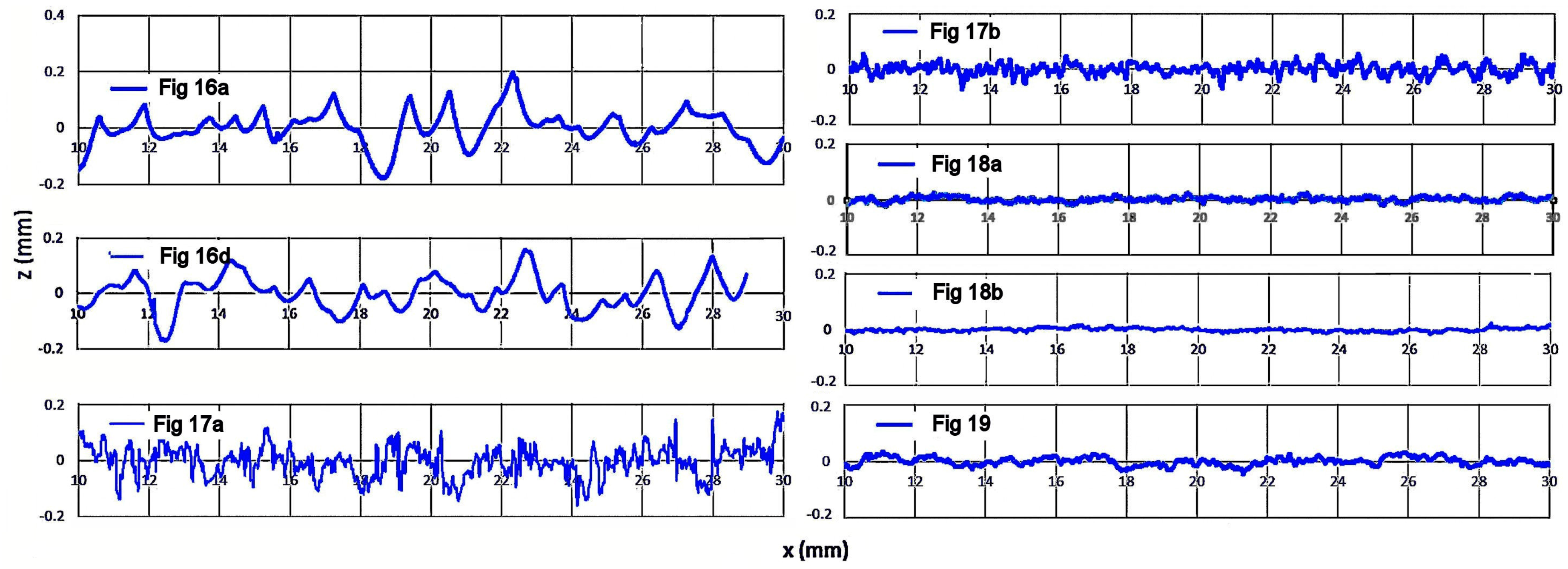
Profiles of the AWJ-etched surfaces were measured with a Cobra 2D Laser Profile Scanner/Digital Range Sensor DRS-500. The profiles are illustrated in Figure 20. The measured surface profiles after trend removal were analyzed and the experimental parameters and the measured root-mean-square (RMS) values of the surface roughness for several etched surfaces that are shown in Figure 16, Figure 17, Figure 18 and Figure 19, were listed in Table 1. Note that the RMS value is equivalent to the Ra of the etched surface. As a rule of thumb, the surface roughness is inversely proportional to the nozzle or workpiece traversing speed, the abrasive size and flow rate, the pressure, and the material hardness. The optimum performance was to use relatively low pressure and fine abrasives to achieve a low material removal rate per pass. Multiple passes could be used to reach the desired depth of etching. It is important to note that for brittle materials such as glass, low-pressure etching is necessary in order to mitigate cracking or chipping.
Table 1 shows that the AlN concave surface (Figure 18b) has the smoothest surface finish followed by the glass convex surface (Figure 18a) as they were etched using the lowest pressure and the finest abrasive together with the second highest traversing speed. On the other hand, the stainless steel flat (Figure 16a) and concave (Figure 16d) surfaces have the roughest finish as they were etched by using the most course abrasives and the slowest traversing speed together with the medium pressure.
The above results demonstrate that waterjet can preferably serve, cost effectively with fast turnaround, as a near-net-shaping tool for etching a variety of surfaces. Precision grinding can then be applied as a secondary process to achieve the required surface finish.
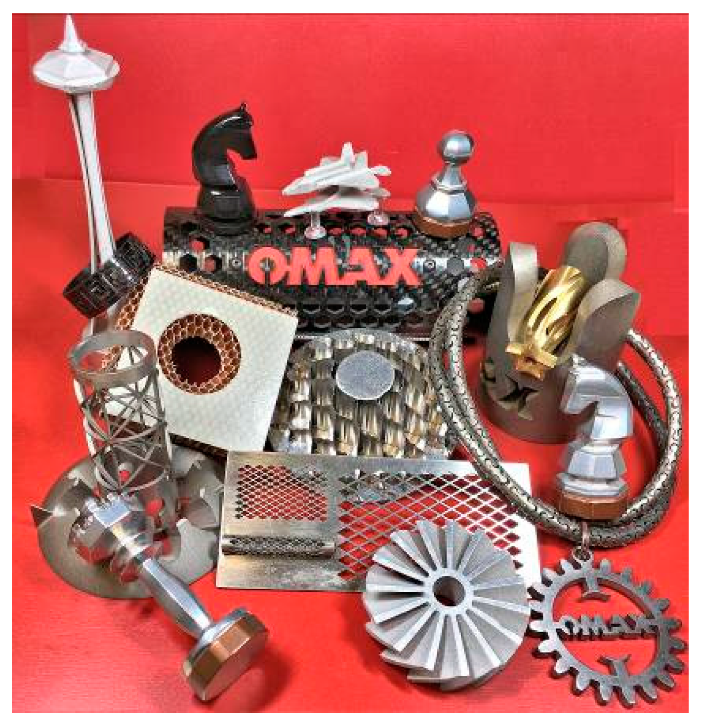
3.8. 3D Machining
There are several methods and setups to machine 3D parts using waterjet [17]. Figure 21 illustrates a collection of several AWJ-machined 3D parts made from various materials, including aluminum, steel, titanium, copper, brass, honeycombs (with aramid and titanium cores), polyethylene, and carbon fiber. These parts were machined with the use of the following accessories:
- No accessory—fighter plane (cut at three different orientations)
- Rotary Axis—space Needle, carbon fiber ring, titanium mesh cage, interlocking necklace, carbon fiber tube, 25 mm OD stainless steel tube, and steel gear
- A-Jet—honeycombs and blisk
- Combined Rotary Axis and A-Jet—chess pieces, steel pipe joint, and brass tube.
By combining the Rotary Axis and A-Jet, complex 3D parts can be readily made. For example, several pieces of the chest set illustrated in Figure 12 were machined with such a setup.
Figure 22 illustrates the photographs of two sets of earrings and one bracelet made from niobium metal. The 2-1/2D patterns of the large earrings were formed by laminating two layers of niobium metal with different patterns. The bracelet was first cut on a flat stock with the AWJ and then mechanically shaped to the designed form. By anodizing at different voltages, niobium changes to a spectrum of brilliant color. Supporting the bracelet is a stainless steel tube with an OD of 12.7 mm. The “Ω” interlocking features were machined with the tube mounted on the Rotary Axis. A sacrificial rod was inserted inside to protect the opposite of the tube from damage by the spent abrasives.
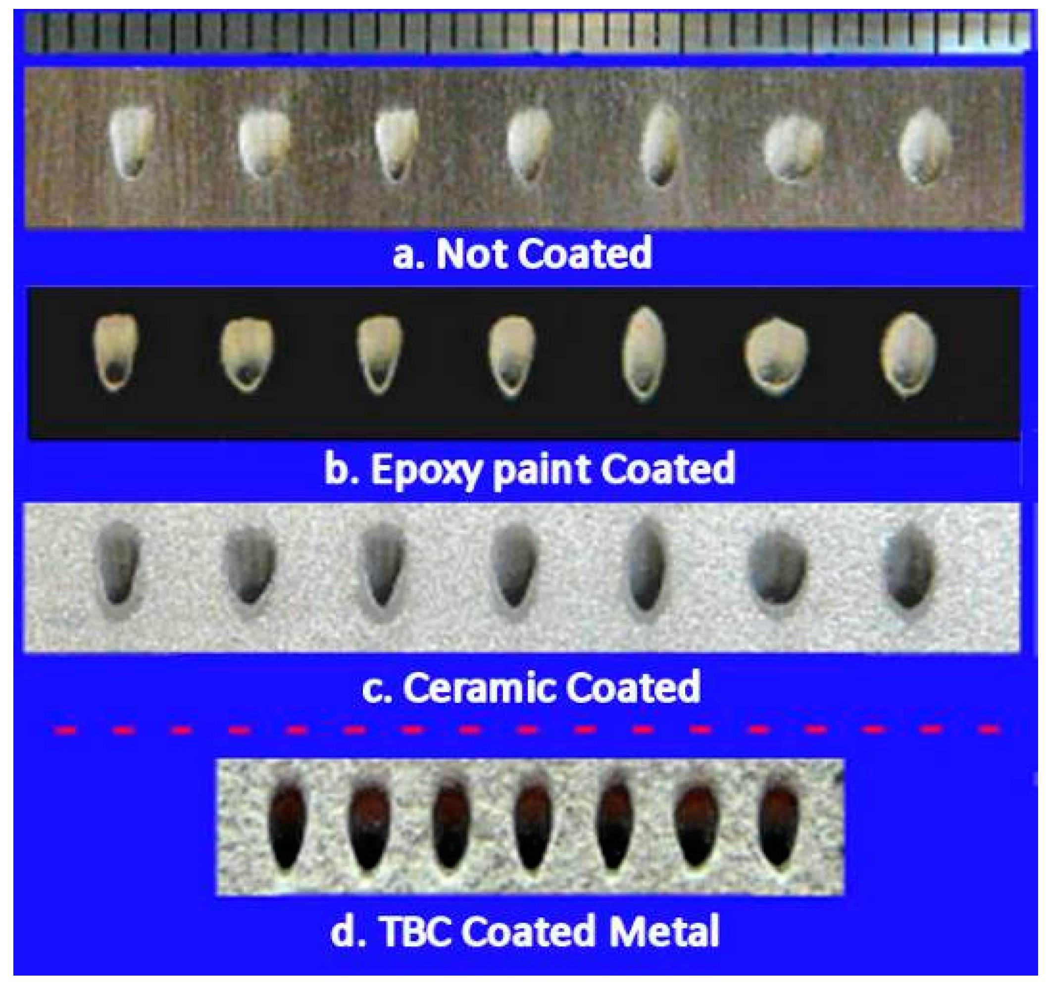
For modern aircraft engines operating at a very high temperature, there is need for drilling inclined and shaped air breathing holes to achieve efficient and maximum cooling. The AWJ was applied successfully to drill such holes on refractory metals with and a without thermal barrier coating. Figure 23 illustrates such holes drilled with AWJ. By mounting the workpiece on the Rotary Axis, any inclined angle of the holes can be drilled. The geometries of the holes were drilled by controlling the tilting of the A-Jet. Within a certain limitation, the inclined angle and the shape can vary simultaneously along the hole axis. In the test samples shown in Figure 23, the inclined angles of the holes are fixed. The AWJ nozzle consisted of a 0.18-mm ID diamond orifice and a 0.38-mm ID mixing tube. A garnet of 220 mesh with a flow rate of 45 gm/min was used. Seven hole geometries were drilled into these samples to demonstrate the flexibility of the AWJ hole drilling process. Note that the hole geometries shown in Figure 23d differed from the others. Most important, there was no delamination between the coatings and substrates and no HAZ on the hole edges in the substrates. The current practice requires a two-step process to drill inclined and shaped holes on TBC coated metal. First, the nonconductive TBC is removed with a laser and the hole in the substrate is drilled with an EDM process.
4. Conclusions
With the award winning MicroMAX available commercially, the versatile waterjet has established the full capability of precision machining of most materials from macro to micro scales—the “7M” advantage. AWJ-machined sample parts made from various materials from metal, non-metal, to anything in between were presented to demonstrate such versatility. Accessories such as the Rotary Axis and the A-Jet were used separately and/or simultaneously to produce 2D and 3D features for a wide range of part size and thicknesses. In summary, waterjet inherently possesses technological and manufacturing merits that are unmatched by most machine tools particularly for machining advanced materials that are too delicate or too difficult to machine otherwise. As a cold cutting process that is material independent, for example, waterjet cuts both reflective and nonconductive materials at considerably faster speeds than wire EDM and solid- state lasers do. Note that EDM and lasers are material selective; there is considerable challenge to cut nonconductive and reflective materials with EDM and lasers, respectively. In order to minimize the HAZ, wire EDM must carry out with multi-passes, whereas lasers must pulse at high frequencies. One of the goals of this paper is to raise the awareness of the latest advancement in waterjet technology and its versatility as a precision machine tool for a wide range of applications. Even for extremely precise parts, waterjet may serve as a cost effective near-net shaping tool.
Acknowledgments
This work was supported by an independent research and development (IR&D) fund from OMAX Corporation. The research and development of the micro abrasive waterjet technology was supported by NSF SBIR Phase 1 and 2 Grants (No. 0944239 and 1058278). Any opinions, findings, and conclusions or recommendations expressed in this material are those of the authors and do not necessarily reflect the views of the NSF. Special thanks are to Messrs. Chan Srey and Ruvim Mironyuk for sharing the parts they machined. In particular, the excellent carbon fiber ukulele, the chess set, and quadrones were designed, machined and assembled by Mironyuk.
Conflicts of Interest
The author declare no conflict of interest.
References
- Rasmussen, B. Market Trend: This Industry is Ready to Explode. Zoltek: Industry News. March 2008. Available online: http://www.compositesworld.com/columns/market-trends-this-industry-is-ready-to-explode (accessed on 5 September 2017).
- Zelinski, P., Sr. (Ed.) Machining at Mach 3. MMSOnline.com. February 2009. Available online: http://www.mmsonline.com/articles/machining-at-mach-3 (accessed on 5 September 2017).
- Mrazova, M. Advanced composite materials of the future in aerospace industry. INCAS Bull. 2013, 5, 139–150. [Google Scholar] [CrossRef]
- Liu, H.-T.; Schubert, E.; McNiel, D.; Soo, K. Applications of Abrasive-Waterjets for Precision Machining of Composites. In Proceedings of the SAMPE 2010 Conference and Exhibition, Seattle, WA, USA, 17–20 May 2010. [Google Scholar]
- Liu, H.-T. Machining Honeycomb Composites with Ultrahigh-Pressure Abrasive Waterjets. In Proceedings of the 18th International Conference on Water Jetting, Gdansk, Poland, 13–15 September 2006. [Google Scholar]
- Liu, H.-T. Abrasive-waterjet machining of most materials from macro to micro scales. In Proceedings of the TechConnect World Innovation Conference and Expo, Washington, DC, USA, 14–17 June 2015. [Google Scholar]
- Liu, H.-T. Precision machining of advanced materials with abrasive waterjets. IOP Conf. Ser Mater. Sci. Eng. 2017. [Google Scholar] [CrossRef]
- Edelstein, A.S.; Cammarata, R.C. (Eds.) Nanomaterials: Synthesis, Properties, and Applications; Taylor & Francis: New York, NY, USA, 1996; p. 593. [Google Scholar]
- Black, S. Abrasive machining methods for composites. High Perform. Compos. 2004, 12, 32–37. [Google Scholar]
- Hashish, M. When Abrasive Waterjets Shine. The Fabricator.com. 14 September 2004. Available online: http://www.thefabricator.com/WaterjetCutting/WaterjetCutting_Article.cfm?ID=955 (accessed on 5 September 2017).
- Liu, H.-T.; Fang, S.; Hibbard, C. Enhancement of Ultrahigh-Pressure Technology with LN2 Cryogenic Jets. In Proceedings of the 10th American Waterjet Conference, Houston, TX, USA, 14–17 August 1999. [Google Scholar]
- Liu, H.-T. Flash Vaporizing Water Jet and Piercing with Flash Vaporization. U.S. Patent 7,815,490, 19 October 2010. [Google Scholar]
- Liu, H.-T. Versatility of micro abrasive waterjet technology for machining nanomaterials. In Dekker Encyclopedia of Nanoscience and Nanotechnology, 3rd ed.; Taylor and Francis: New York, NY, USA, 2017. [Google Scholar]
- Liu, H.-T.; Schubert, E. Micro Abrasive-Waterjet Technology (Chapter Title). In Micromachining Techniques for Fabrication of Micro and Nano Structures; Mojtaba, K., Ed.; INTECH Open Access Publisher: Rijeka, Croatia, 2012; pp. 205–234. ISBN 978-953-307-906-6. Available online: http://cdn.intechweb.org/pdfs/27087.pdf (accessed on 5 September 2017).
- Shanmugam, D.K.; Nguyen, T.; Wang, J. A study of delamination on rapite/epoxy composites in abrasive waterjet machining. Compos Part A Appl. Sci. Manuf. 2008, 39, 923–929. [Google Scholar] [CrossRef]
- Ravi-Chandar, K.; Satapathy, S. Mechanical Properties of G-10 Glass-Epoxy Composites; Institute for Advanced Technology, The University of Texas at Austin: Austin, TX, USA, 2007; p. 10, IAT.R 0466; Available online: http://www.dtic.mil/dtic/tr/fulltext/u2/a470630.pdf (accessed on 5 September 2017).
- Liu, H.-T.; Olsen, J.H. Application of AWJ for 3D Machining. In Proceedings of the WJTA-ICMA Conference and Expo, Houston, TX, USA, 9–11 September 2013. [Google Scholar]
- Khalajhedayati, A.; Pan, Z.; Rupert, T.J. Manipulating the interfacial structure of nanomaterials to achieve a unique combination of strength and ductility. Nat. Commun. 2016, 7, 1–8. [Google Scholar] [CrossRef] [PubMed]
- Liu, H.-T. Roles of taper compensation in AWJ precision machining. In Proceedings of the International Conference on Water Jetting, Seattle, WA, USA, 16–18 November 2016. [Google Scholar]
- Kluger, J.M.; Sapsis, T.P.; Slocum, A.H. High-resolution and large force-range load cell by means of nonlinear cantilever beams. Precis. Eng. 2016, 43, 241–256. [Google Scholar] [CrossRef]
- Kluger, J.M.; Sapsis, T.P.; Slocum, A.H. Ring-based stiffening flexure applied as a load cell with high resolution and large force range. ASME J. Mech. Des. 2017, 139, 103501. [Google Scholar] [CrossRef]
- Liu, H.-T. Hole drilling with abrasive fluidjets. Int. J. Adv. Manuf. Technol. 2007, 32, 942–957. [Google Scholar] [CrossRef]
- Liu, H.-T.; Miles, P.; Hibbard, C.; Cooksey, N. Measurements of water-droplet and abrasive speeds in waterjets and abrasive waterjets. In Proceedings of the 10th American Waterjet Conference, Houston, TX, USA, 14–17 August 1999. [Google Scholar]
- Liu, H.-T.; Hovanski, Y.; Caldwell, D.D.; Williford, R.E. Low-Cost Manufacturing of Flow Channels with Multi-Nozzle Abrasive-Waterjets: A Feasibility Investigation. In Proceedings of the 19th International Conference on Water Jetting, Nottingham, UK, 15–17 October 2008. [Google Scholar]
- Liu, H.-T. Near-Net Shaping of Optical Surfaces with Abrasive Suspension Jets. In Proceedings of the 14th International Conference on Jetting Technology, Brugge, Belgium, 21–23 September 1998; pp. 285–294. [Google Scholar]
Figure 1.
MicroMAX JetMachining Centers (JMC).

Figure 2.
Large format 160X JMC.
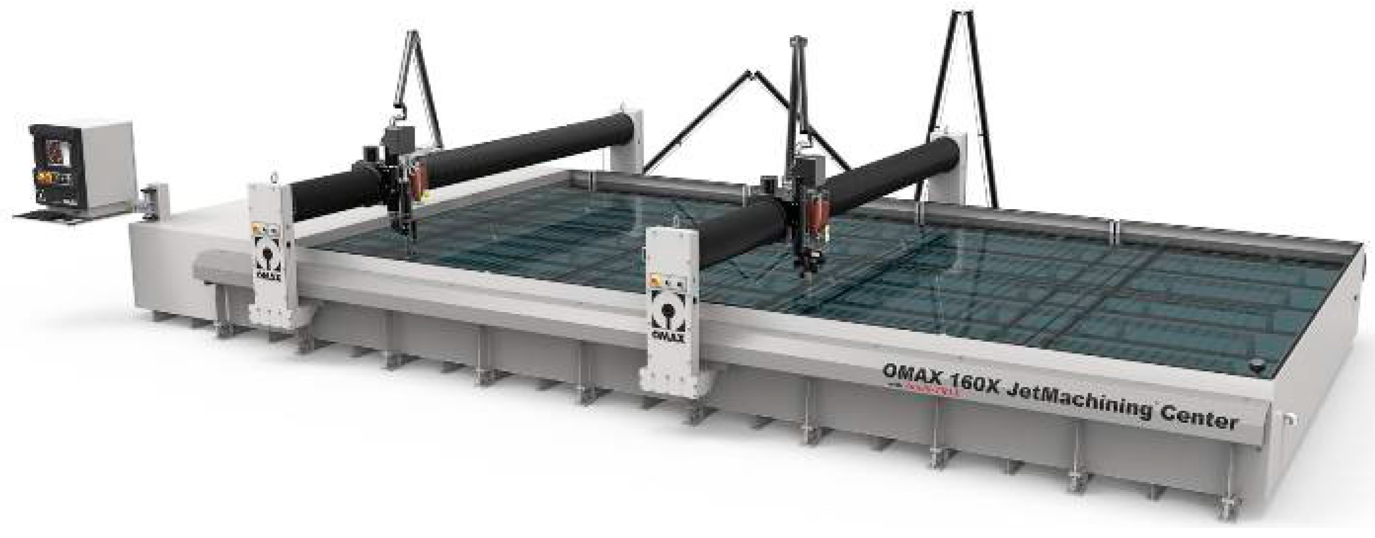
Figure 3.
AWJ nozzles.

Figure 4.
Accessories for 3D machining.

Figure 5.
Material independence of AWJ machining.
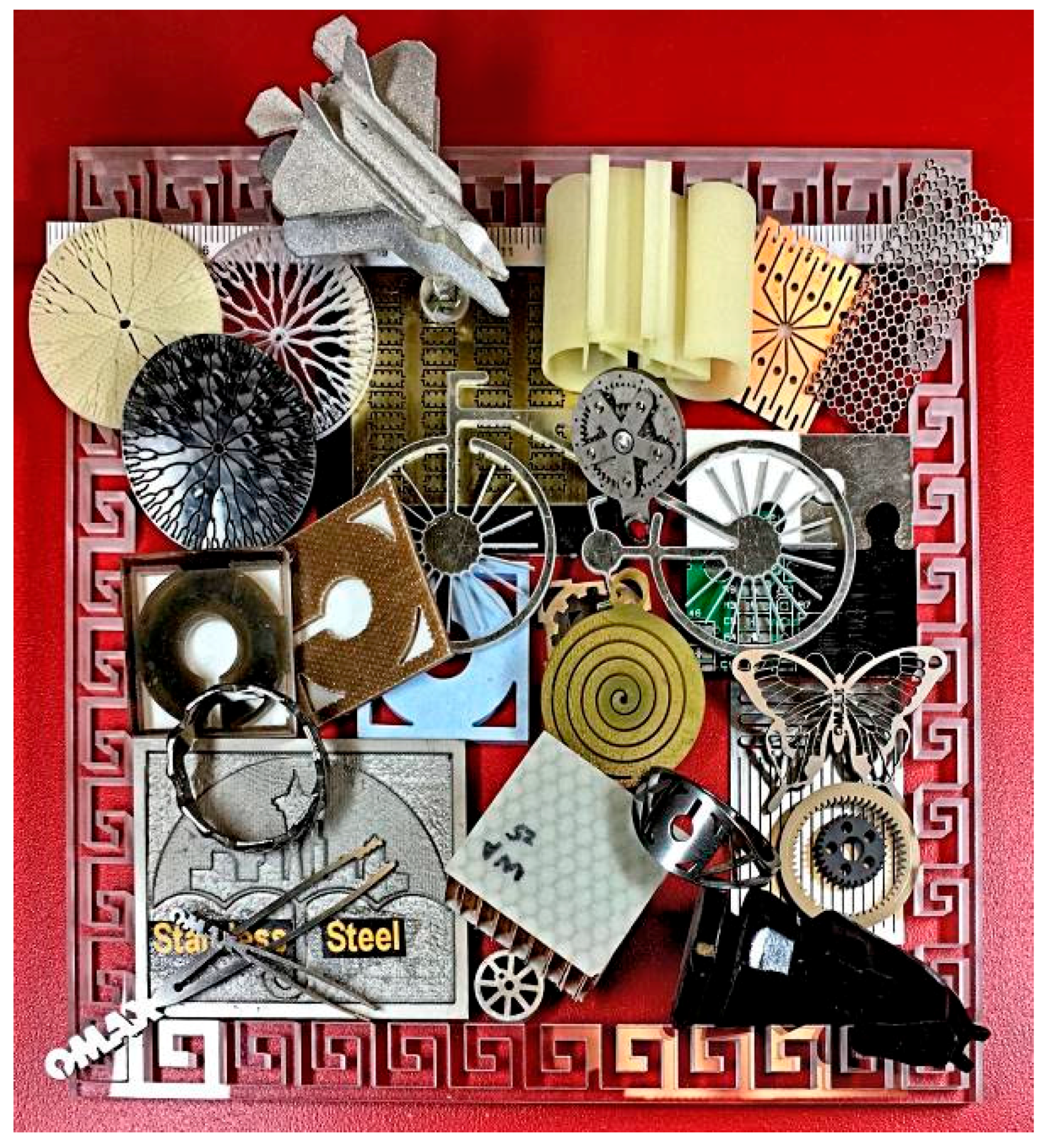
Figure 6.
AWJ-cut internal features on delicate materials.
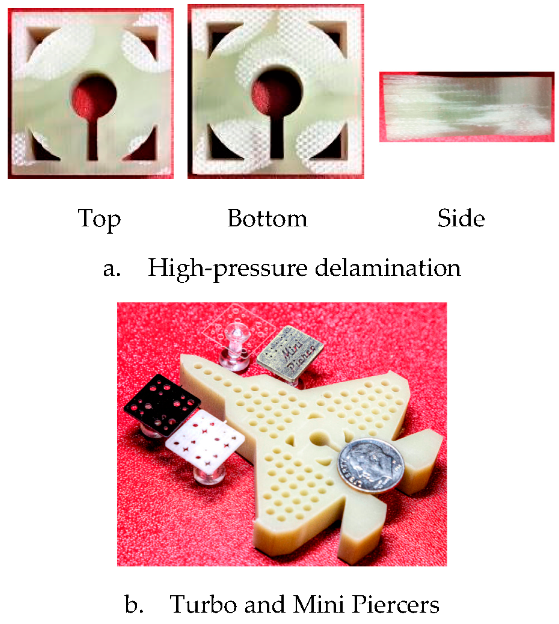
Figure 7.
Planetary gears made from titanium and PEEK without and with fiber reinforcement.

Figure 8.
Two AWJ-cut gears with vastly different size and thickness.
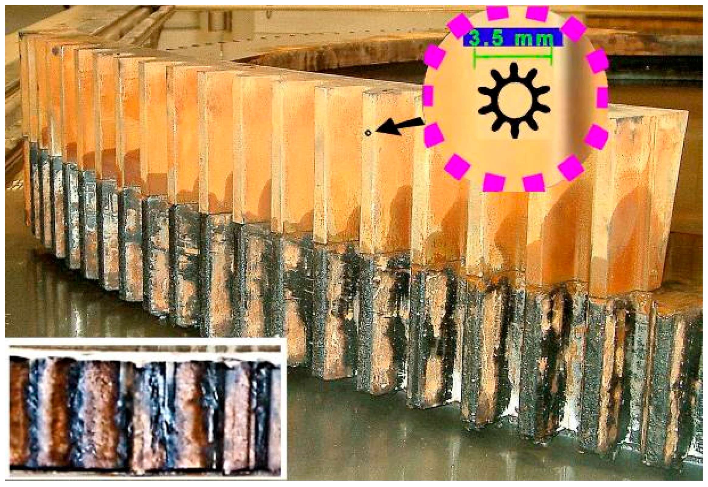
Figure 9.
B777 aircraft model and quadrones.

Figure 10.
Carbon fiber ukulele.
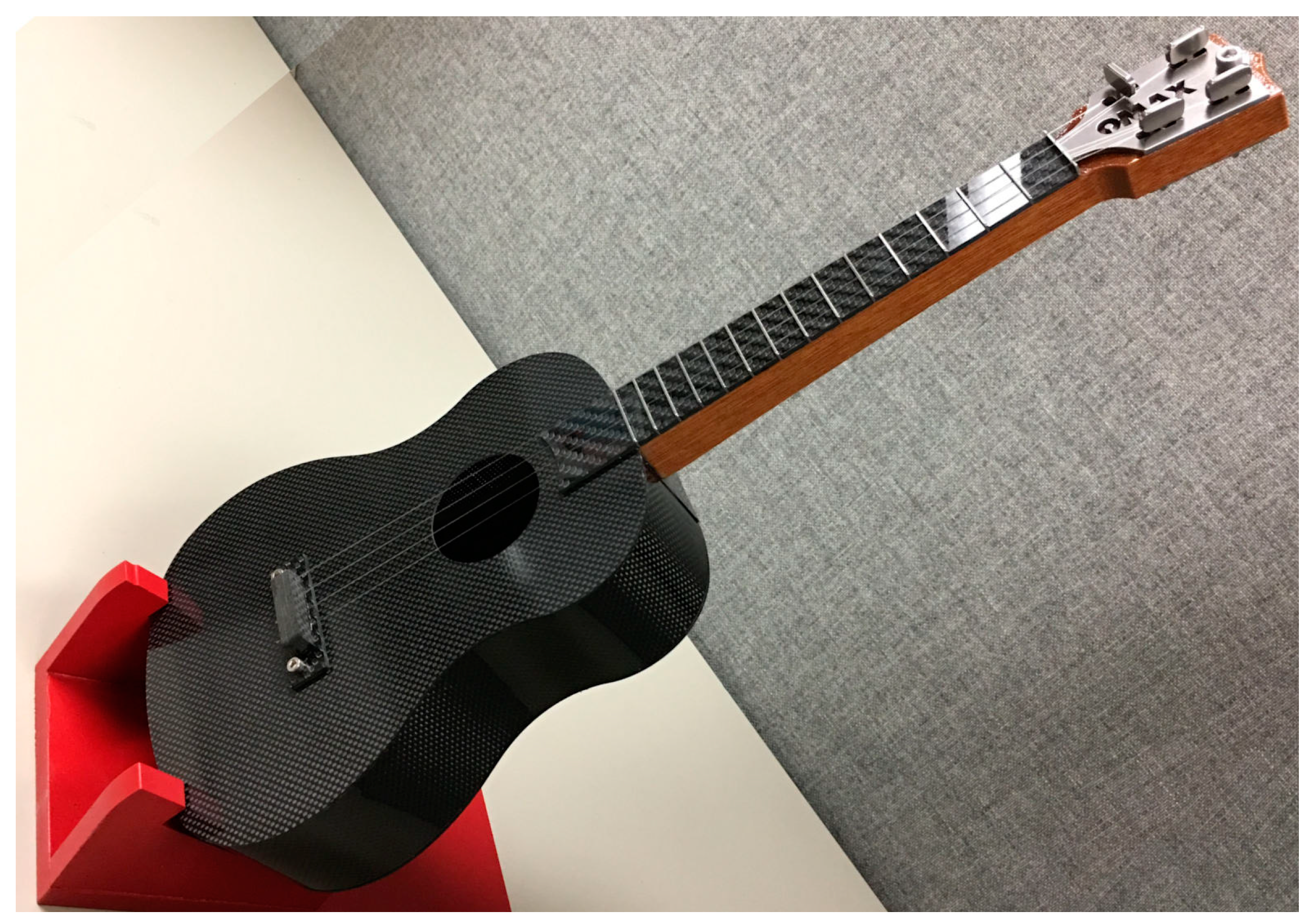
Figure 11.
Miniature parts machined with 7/15 and 5/10 nozzles (courtesy of MIT CBA).

Figure 12.
AWJ-cut 3D chess set and board made from several materials.
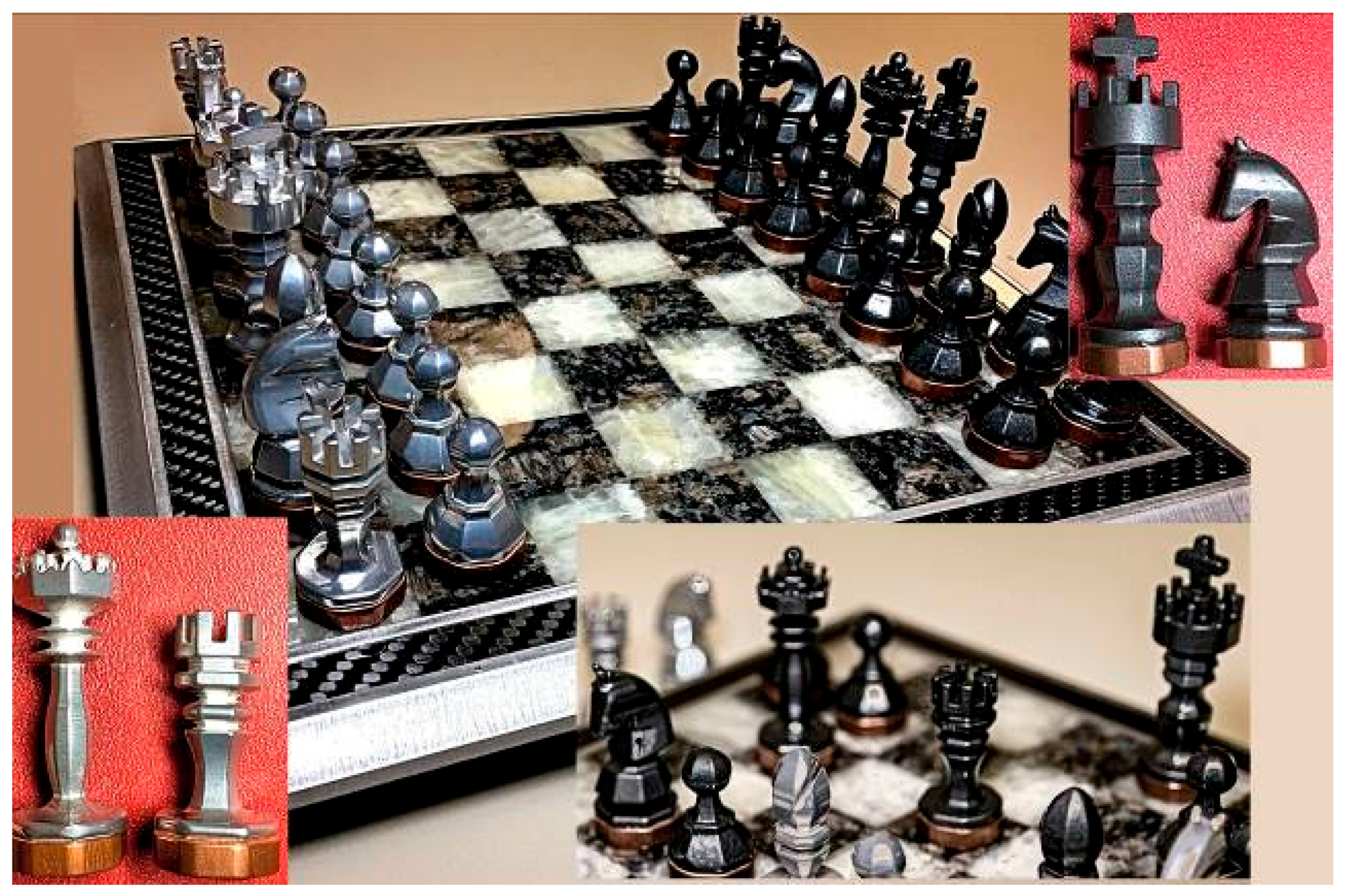
Figure 13.
Nonlinear Load Cells (Courtesy of MIT ME Department).
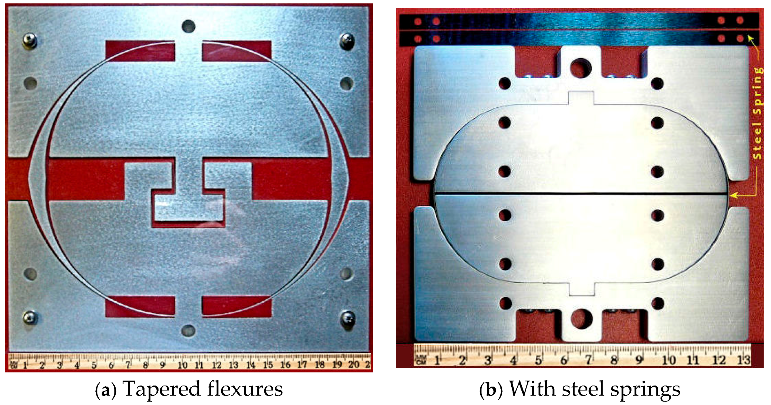
Figure 14.
AWJ-drilled blind holes.
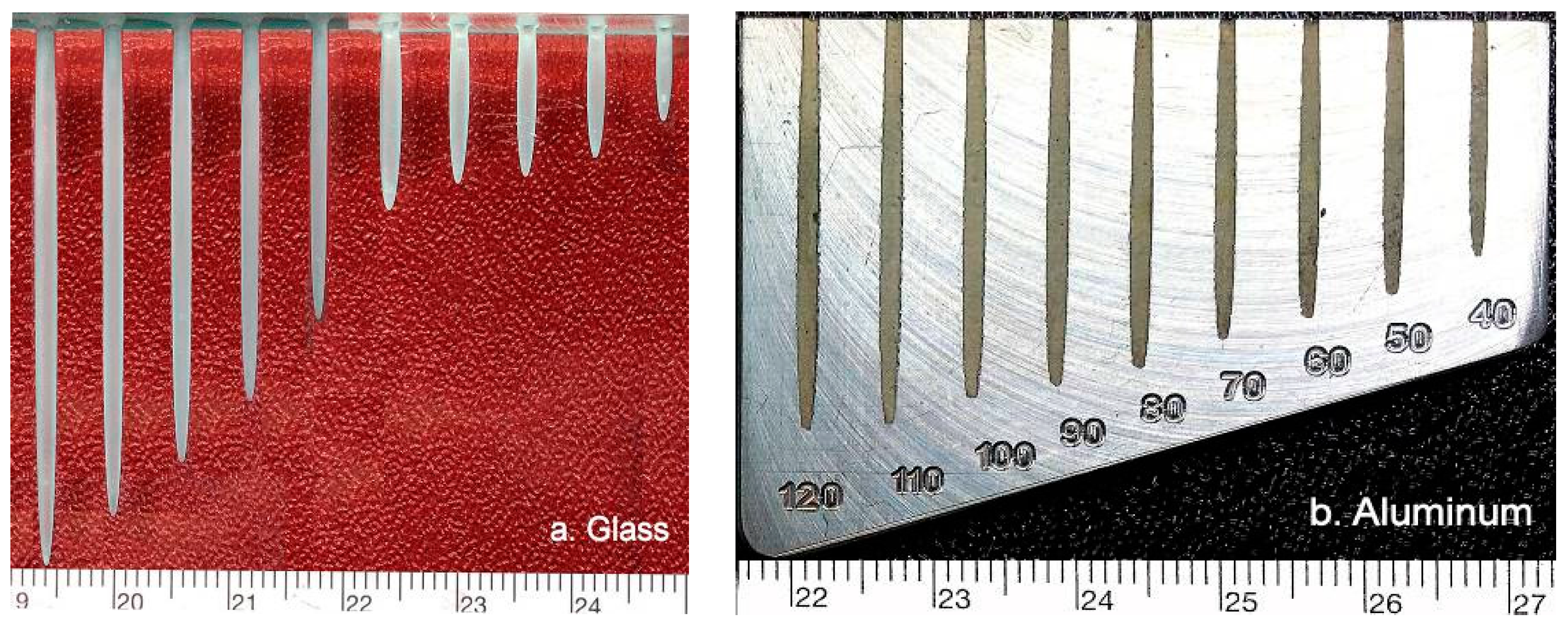
Figure 15.
AWJ-etched copper part.

Figure 16.
AWJ-etched stainless steel parts.

Figure 17.
AWJ-etched grooves.

Figure 18.
Near-net-shaped surfaces etched with ASJ on glass and AIN [25].
Figure 18.
Near-net-shaped surfaces etched with ASJ on glass and AIN [25].
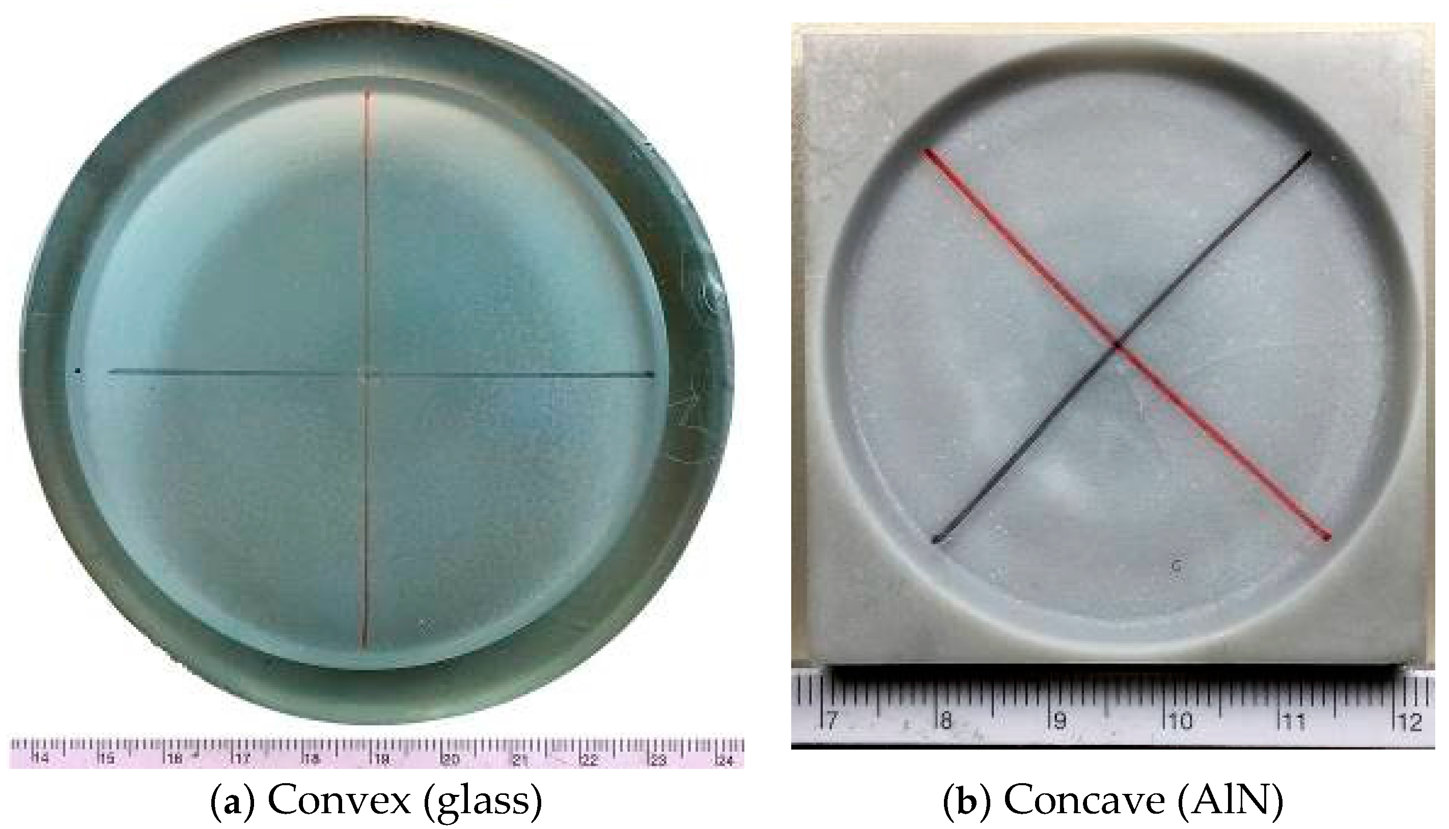
Figure 19.
AWJ-etched glass pockets.
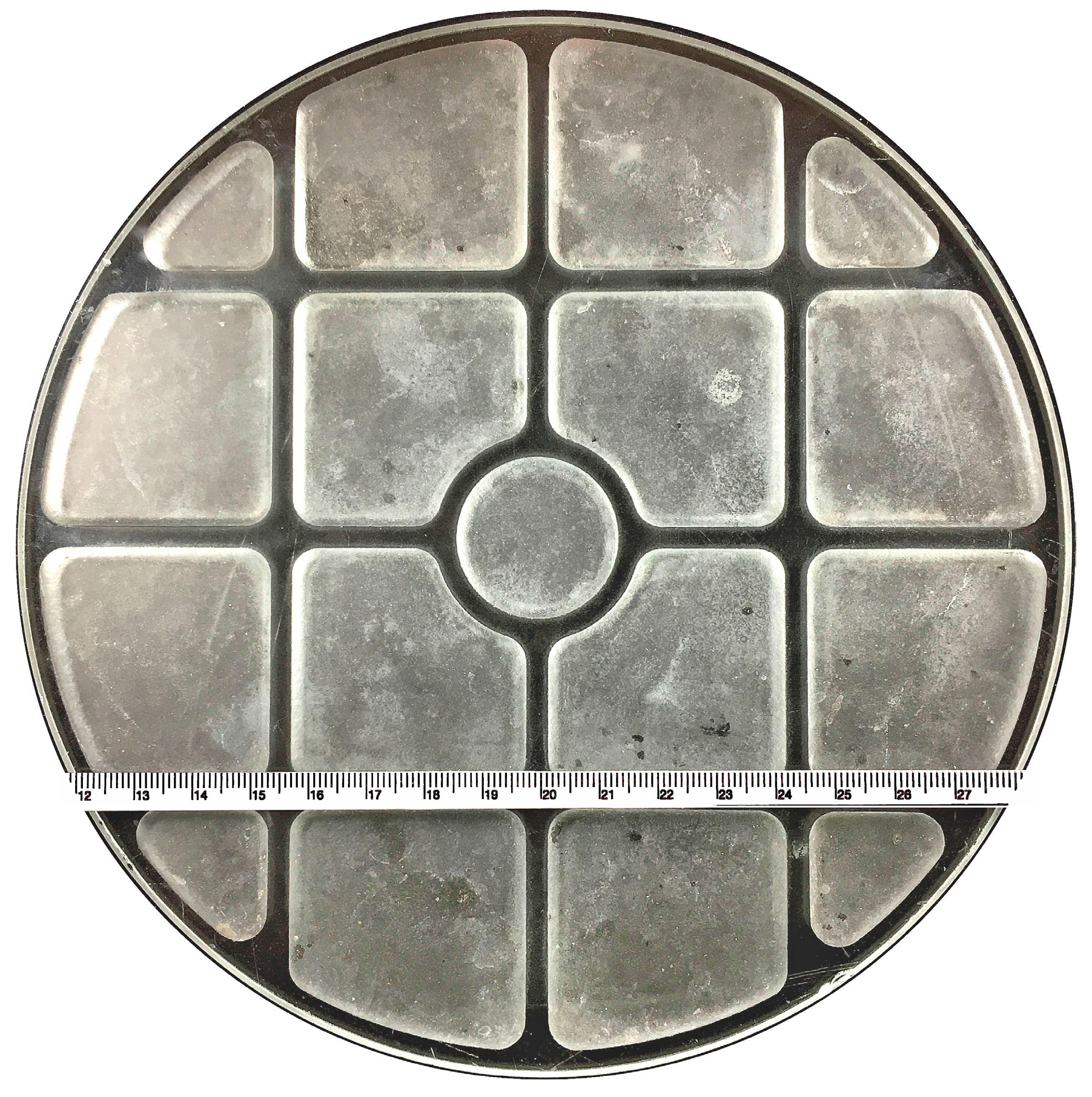
Figure 20.
Selected profiles of AWJ-etched surfaces illustrated in Figure 16, Figure 17, Figure 18 and Figure 19.

Figure 21.
Collection of AWJ-machined 3D parts.

Figure 22.
AWJ-machined jewelries.

Figure 23.
AWJ-drilled inclined/shaped holes on metals.


Table 1.
Test parameters and for AWJ/ASJ etching.
| Material/Configuration | Mask | Pressure (MPa) | Traversing Speed (m/s) | Number of Pass | Abrasive (mesh) | RMS (mm) |
|---|---|---|---|---|---|---|
| Stainless Steel_flat (Figure 16a) | No | 138 | ~0.013 | Single | Garnet (80) | 0.061 |
| Stainless Steel_Concave (Figure 16d) | No | 138 | ~0.013 | Single | Garnet (80) | 0.062 |
| Lexan/DDA (Figure 17a) | Yes | 345 | 31.42 | Multiple | No | 0.051 |
| Stainless Steel/DDA (Figure 17b) | Yes | 345 | 31.42 | Multiple | Garnet (120) | 0.020 |
| Glass Convex/ASJ (Figure 18a) | No | 52–69 | 13.09 | Multiple | Garnet (~320) | 0.008 |
| Aluminum Nitrite (AlN)/ASJ (Figure 18b) | No | 52–69 | 13.09 | Multiple | Garnet mixed with Al2O3 (~320) | 0.006 |
| Glass/Pocket (Figure 19) | Yes | 138 | 8.50 | Multiple | Garnet (220) | 0.015 |
© 2017 by the author. Licensee MDPI, Basel, Switzerland. This article is an open access article distributed under the terms and conditions of the Creative Commons Attribution (CC BY) license (http://creativecommons.org/licenses/by/4.0/).
Share and Cite
MDPI and ACS Style
Liu, H.-T. “7M”Advantage of Abrasive Waterjet for Machining Advanced Materials. J. Manuf. Mater. Process. 2017, 1, 11. https://doi.org/10.3390/jmmp1010011
AMA Style
Liu H-T. “7M”Advantage of Abrasive Waterjet for Machining Advanced Materials. Journal of Manufacturing and Materials Processing. 2017; 1(1):11. https://doi.org/10.3390/jmmp1010011
Chicago/Turabian StyleLiu, (Peter) H.-T. 2017. "“7M”Advantage of Abrasive Waterjet for Machining Advanced Materials" Journal of Manufacturing and Materials Processing 1, no. 1: 11. https://doi.org/10.3390/jmmp1010011