Tube Forming Using a Reuleaux Triangle

Mechanical Engineering, The Pennsylvania State University, The Behrend College, Erie, PA 16563, USA
*
Author to whom correspondence should be addressed.
J. Manuf. Mater. Process. 2017, 1(2), 16; https://doi.org/10.3390/jmmp1020016
Submission received: 1 September 2017
/
Revised: 3 November 2017
/
Accepted: 10 November 2017
/
Published: 13 November 2017
Abstract
:Tube forming is a manufacturing process in which a circular tube is deformed into various shapes. This paper details a novel process in which tubular steel was formed into a square tube using a Reuleaux triangle tool. This triangular section tool translates on its section and rotates on its longitudinal axis to prepare a square geometry. It is hypothesized that the sliding action increases the formability of the part. After comparison with the square tool tube flaring, which only longitudinally translates to form a square tube, it is found that only 11% of the force is required to achieve the shape.
1. Introduction
Thin walled metal tubes with square cross sectional geometry are desirable for many applications. Non-uniform tube ends, including square shaped tube ends are useful in various structural and fluid flow applications. In this paper, a novel tube forming method is explored. In this new method, the circular tube is formed to square shape using a triangular tool. This unique idea was first devised and proposed by Morrell et al. [1] in 1978. It was proposed to drill a square hole from a drill bit which would not only rotate in longitudinal axis but also makes a planar motion on perpendicular to its longitudinal axis to make a square profile. The profile on which the tool makes it planar motion is important to achieve a desired shape and thus is one of the important part of this novel approach. This method was first used by an author in sheet metal forming area to simulate the square cup and tube [2,3] and no other literature are available on this process. This innovative method was now used to experimentally form the square tube from the circular tubular section in this paper and thus directly falls under tube forming processes.
Forming of various tube geometries can be obtained and characterized under tube forming processes in which the expansion or reduction of cross-section or bending the tube by either using a solid mandrel or a fluid pressure are performed. These tubular parts are in various scales from micro to macro. In this paper, the method was used to expand or stretch the tube by flaring the tube. In tube flaring the tube is stretched essentially using a circular conical punch. The force required to flare the tube of same internal diameter but different thickness was found to be in directly proportional to the tube thickness value [4]. It was also noticed that the slope of force ramps is in direct relation with the tube thickness. To achieve different shapes, oval or elliptical punches were used to flare the tube [5,6]. But for higher deformation in non-circular shape it was suggested that first more generalized circular conical punch should be used till extreme formability and then shape with the non-circular desired shape. However, the material flow was noted to be complex and unpredictable results could be achieved with lack of understanding on the forming history [7]. Sensitivity of various parameters like friction condition, tool cone angle, outer diameter to thickness ratio, die fillet in outward flaring and temperature were studied and observed to be very sensitive to flaring [8,9,10], but with proper selection could lead to stabilities in forming [11,12,13,14]. The question is still unanswered on how to provide higher formability with extremely lower force. In this paper a novel approach of forming square shape using triangle tool is experimented and discussed. The results are compared with the conventional square tool. In addition, the full formability is studied and differences are listed.
2. Experimental Methodology
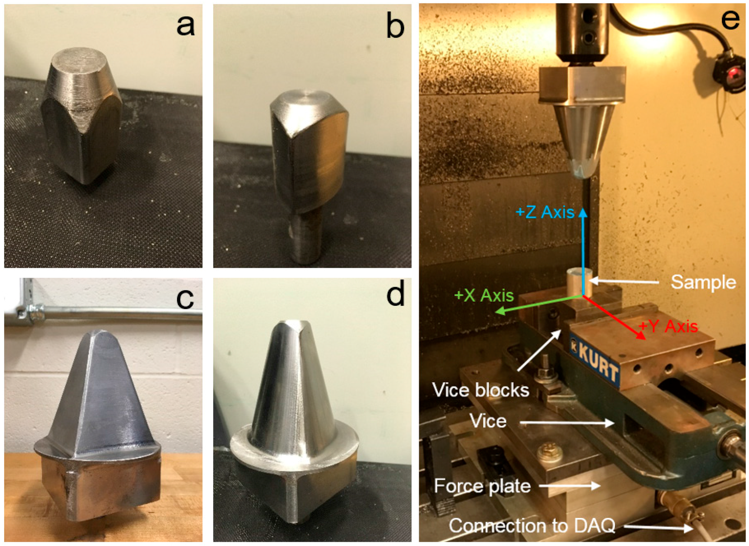
The material considered to perform this study was mild steel welded tubes with 38.1 mm outer diameter and 1.25 mm as thickness. Four sets of experiments were performed: (a) Square straight tool (SQ-ST)—where the tool cross-section is square in shape (Figure 1a) and its size is constant along the longitudinal direction; (b) Reuleaux triangle straight tool (RT-ST)—where a constant width triangular cross section size is constant along the longitudinal direction (Figure 1b); (c) Square taper tool (SQ-T) (Figure 1c) and (d) Reuleaux triangle taper tool (RT-T) (Figure 1d). Three repetitions were performed on each four set of experiments to confirm the repeatability. The best results were analyzed and presented. Both taper tools were drafted with 15° angle along longitudinal direction. All tube samples were cut to a length of 88.9 mm. For each sample the inside of one end was lightly sanded and the entire inside length of each sample was cleaned with a paper towel to remove any small burrs or debris. The samples were examined to ensure that the area of contact with the tool should not be damaged.
2.1. Square Tool Tube Forming
Square tool experiments were performed on a Tinius-Olsen 120 kip machine. In each experiment, the samples were placed on a bottom platen and the tool was mounted to the driving crosshead of the hydraulic press. The tube was oriented such that the tool corner should not see the weld line to eliminate premature failure. The crosshead speed of 5 mm/min was set for deformation. Ford Motorcraft PTFE lubricant was used in all experiments to reduce the friction.
2.2. Reuleaux Triangle Tube Forming
The Reuleaux triangle tool experiments were conducted using a computer numerical control (CNC) machine (Figure 1e). The process to drill the square shape from the triangle cutting tool came from the [15]. This idea has been taken to form the square shaped tube starting from the circular tube. The tool not only rotates on its vertical axis but also makes the planar motion on its horizontal plane. The steps to create the Reuleaux triangle is given in [2,3]. The center point of reuleaux triangle was programed with G-code in such a way that for each tool rotation on vertical axis, tool was making three planar motions to make a square shape from circular tube. With this program the tool will also trace the square shape as it incrementally moved down the length of the tube. Similar to previous experiments, all tubes were lubricated with Ford Motorcraft PTFE lubricant. Numerical study on friction effect was detailed in [3]. An AMTI force plate was bolted to the rails of the CNC machine and was used to gather force data during each experiment as shown in Figure 1e. The force plate was connected to a VISHAY data acquisition system which collected force measurements in the X, Y and Z directions with a sampling rate of 1000 Hz. This is the minimum sampling rate the data acquisition system can produce, which is high for the test considered.
2.3. Tube Profile and Thickness Measurement
All deformed tubes top square section was measured by using Brown & Sharpe Gage 2000 coordinate measurement machine (CMM) as shown in Figure 2. This measurement provides the direct comparison on how much tube can be flared before it fractures. The tube was fixed on the table using fixture attachments. Further the probe was calibrated by using the spherical ball of 19.05 mm (0.75 inch) diameter. For calibration the probe made 4 hits on the equator of the ball and one on the apex. This confirms the coordinate calibration. The tube was originally marked by the sharpie on the top square quarter section thickness. The probe was then manually moved to touch those points (see top-right corner inset of Figure 2), approximately and readings were captured in computer, which was then transferred as csv file. The data points were imported to excel and quarter tube square section curves were plotted. Further for those quarter section of all deformed tubes the thickness measurement was performed using Vernier caliper with up to 3 decimal points. The thicknesses were capture at the apex of the all quarter square formed tubes.
3. Result and Discussion
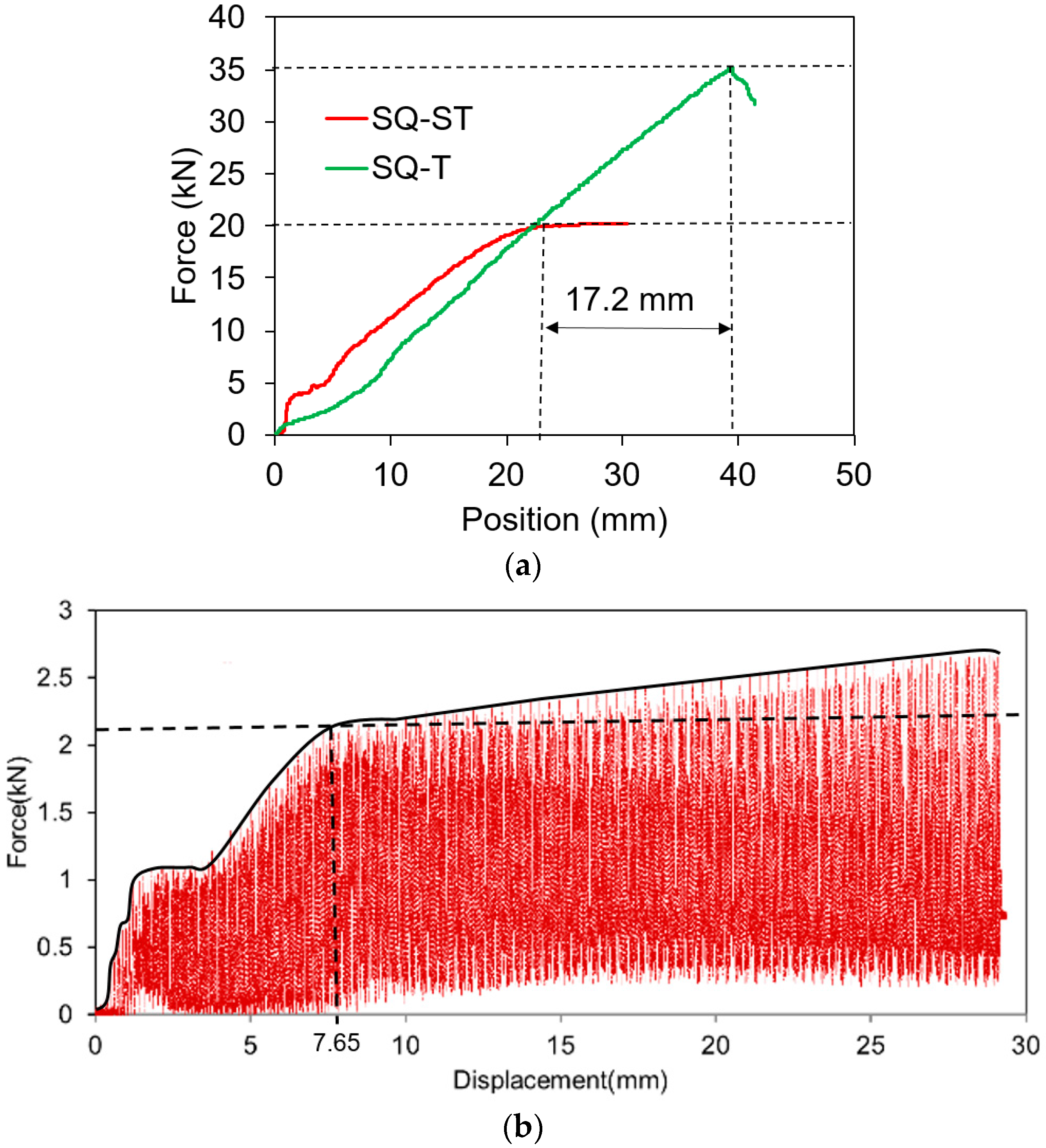
Figure 3a provides the force displacement response in vertical direction i.e., in Z direction during forming the tube using SQ-ST and SQ-T tool. It can be observed that with SQ-ST tool, the tube could form to the desired shape with no failure. To access the total formability of the tube, the SQ-T provides the indication of how more the tube can be flared to square shape before failure. It can be noted that extra 17.2 mm from saturation to failure can be achieved using square tool. In comparison, the saturation was observed at 7.65 mm in RT-ST tube experiment (Figure 3b). Due to vertical movement and rotation and planar translation of the tool, the reaction in all three X, Y and Z direction were recorded. Due to continuous motion of the tool, the data signal is noisy. Other reason may be due to high sampling rate the system can produce (i.e., 1000 data points per second). This was the minimum setting of the system. The Reuleaux triangle tool three vertices were keep on rubbing the tube surfaces during forming. These surfaces are of two geometries, straight edges of square tube and four corners. Due to geometric difference, the material elastic stiffness was different. Thus with an intermittent access of these two geometries by the tool during deformation, the force data was noisy. When compared force data between RT-ST (Figure 3b) and RT-T (Figure 3c), the force variation was high in RT-ST. This is because once the square geometry was formed, it was constantly creating the same profile along the length of the tube. In contrast, in RT-T, the tube was continuously flared with increasing square geometry and thus ramp force was observed. The smaller variation in force in RT-T was found as compared to RT-ST. This is due to more conformance of the formed tube shape around the tool—i.e., more surface area contacts in the Z-axis. The overall trend shows the increase in force during forming. With comparison with SQ-ST the force required during RT-ST is only 11%. The total formability in Reuleaux triangle case was 19.25 mm from saturation to failure was observed (Figure 3c). The displacement gained in RT tool as compared to SQ tool was 2.05 mm.
Due to continuous motion and rotation of tool in Reuleaux case, the X and Y direction forces were also recorded to see the pattern (Figure 3d,e). Dotted black line was applied for RT-ST X-axis force and continuous black line for Y-axis. Both axis lies on the same plane of the square profile and thus and the force graphs were very similar. Similarly, grey line was applied for RT-T X-axis and dark for Y-axis. It was observed that similar forces were required in both RT-ST and RT-T experiments. It was also noted that approximately 20% forces were required as compared to Z direction (i.e., direction of forming).
Figure 4a provides the deformed tubes from all four set of experiments and Figure 4b provides the top end profile. It can be observed that similar profiles were achieved using SQ-ST and RT-ST tool. For SQ-T and RT-T the differences are found. The corner radii do not match and this may be due to the flexibility of the tube when it is forming with the RT-T tool. When the triangular tool three corner hits the surface of the tube, the other surface flex in the direction of motion. Thus, how to acquire the exact corner radius would be the research question for another study. As aforementioned that the RT-T provides the higher flaring than SQ-T by 2.05 mm, the side of the square are little outside.
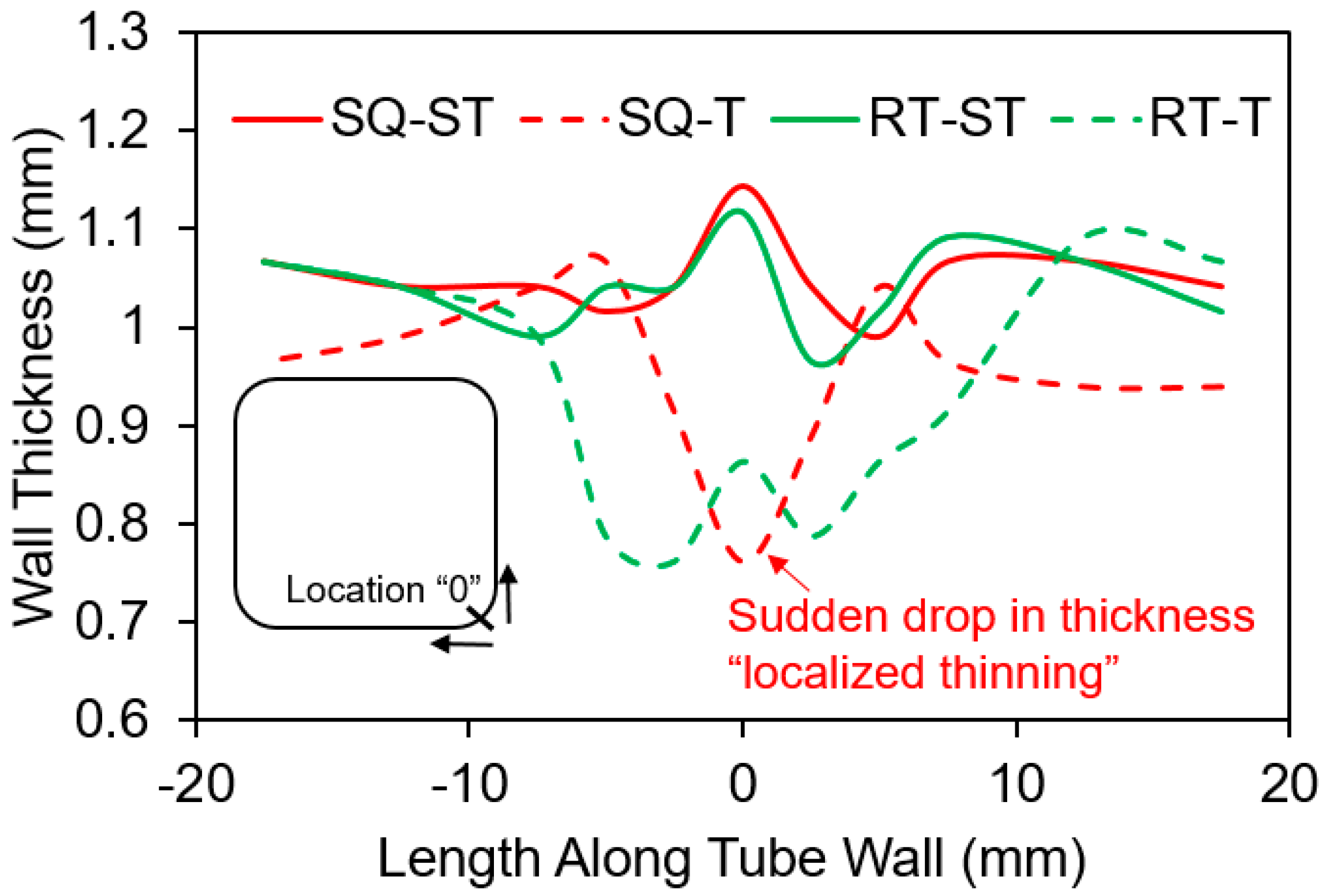
Figure 5 shows the thickness distribution only for the quarter top edge of the square tube. The center of the radius (in case of SQ-ST and RT-ST) and failure edge (in case of SQ-T and RT-T) was considered as a “0” location and thickness was measured in both direction of “0” using Vernier caliper up to 3 decimal places. It can be seen that for SQ-ST and RT-ST the tubes were not thinned much (starting thickness of 1.25 mm and final deformed thickness is around 1.1 mm) and shows more uniformity across the section. This is because the less forming was done on these cases and failure was not yet achieved due to no continuous flaring. As in case of SQ-T and RT-T, the total formability was tested till specimen failure and thus specimen shows more thinning. It can be noted that the localized thinning was occurred in SQ-T and thus failed earlier than RT-T by 2.05 mm of tool Z displacement. It was also noted that the thinning is more uniform in case of RT-T and thus delayed the failure.
4. Conclusions
In this paper a new process to form the square tube is introduced. This new process was based on drilling a square hole from a drill tool. For this Reuleaux triangle was created to experiment the square tube forming. For comparison the conventional square tool was used to form the same dimension square tube. Two additional tools in each case were made with taper to access the full formability. Upon experiment and analysis it was observed that the force required is only 11% in case of Reuleaux triangle as compared to conventional square tool in the direction of forming. It was also observed that more formability is achieved with the use of the Reuleaux triangle than with the conventional method. This result is in line with the thinning aspect of the tube, as thinning is more uniform in the Reuleaux triangle and thus delays the failure in the tube.
Acknowledgments
The authors would like to greatly acknowledge the support from Penn State Erie—The Behrend College for undergraduate research funding. Special thanks go to Glenn Craig for technical support during the experiments and to David Clippinger for helping with the tube profile measurements using the coordinate measurement machine.
Author Contributions
Literature search: Chetan Nikhare; Figures: Chetan Nikhare, Hayden Seibert and Laurentiu Petrut; Study Design: Chetan Nikhare, Hayden Seibert and Laurentiu Petrut; Data Collection: Hayden Seibert and Laurentiu Petrut; Data Analysis: Chetan Nikhare, Hayden Seibert and Laurentiu Petrut; Data interpretation: Chetan Nikhare, Hayden Seibert and Laurentiu Petrut; Paper writing: Chetan Nikhare, Hayden Seibert and Laurentiu Petrut.
Conflicts of Interest
The authors declare no conflicts of interest.
References
- Morrell, R.J.; Gunn, J.A.; Gore, G.D. Square Hole Drill. U.S. Patent No. 4,074,778, 21 February 1978. [Google Scholar]
- Nikhare, C.; Ihrig, M. A New Approach to Form Square Cup. In Proceedings of the International Deep Drawing Research Group Conference, Paris, France, 1–4 June 2014; pp. 1–6. [Google Scholar]
- Nikhare, C. An Investigation of Tube Forming Using Reuleaux Triangle. In Proceedings of the International Deep Drawing Research Group Conference, Linz, Austria, 12–15 June 2016; pp. 310–323. [Google Scholar]
- Nikhare, C. Investigation of Strain Development in Various Tube Thicknesses to Diameter Ratio during Tube Flaring Process. In Proceedings of the International Deep Drawing Research Group Conference, Shanghai, China, 31 May–3 June 2015; pp. 141–150. [Google Scholar]
- Nikhare, C.; Korkolis, Y.P.; Kinsey, B.L. Numerical Investigation of Residual Formability and Deformation Localization during Continuous-Bending-under-Tension. In Proceedings of the International Manufacturing Science and Engineering Conference, Notre Dame, IN, USA, 4–8 June 2012; Volume 48. [Google Scholar]
- Nikhare, C.P.; Korkolis, Y.P.; Kinsey, B.L. Formability Enhancement in Titanium Tube-Flaring by Manipulating the Deformation Path. J. Manuf. Sci. Eng. 2015, 137, 051006. [Google Scholar] [CrossRef]
- Huang, Y.M. Finite element analysis of tube flaring process with a conical tool. Int. J. Adv. Manuf. Technol. 2004, 24, 91–97. [Google Scholar] [CrossRef]
- Rosa, P.A.R.; Rodrigues, J.M.C.; Martins, P.A.F. External inversion of thin-walled tubes using a die: Experimental and theoretical investigation. Int. J. Mach. Tools Manuf. 2003, 43, 787–796. [Google Scholar] [CrossRef]
- Rosa, P.A.; Rodrigues, J.M.; Martins, P.A. Internal inversion of thin-walled tubes using a die: Experimental and theoretical investigation. Int. J. Mach. Tools Manuf. 2004, 44, 775–784. [Google Scholar] [CrossRef]
- Almeida, B.P.P.; Alves, M.L.; Rosa, P.A.R.; Brito, A.G.; Martins, P.A.F. Expansion and reduction of thin-walled tubes using a die: Experimental and theoretical investigation. Int. J. Mach. Tools Manuf. 2006, 46, 1643–1652. [Google Scholar] [CrossRef]
- Yang, H.; Sun, Z.C.; Jin, Y.J. FEM analysis of mechanism of free deformation under dieless constraint in axial compressive forming process of tube. J. Mater. Process. Technol. 2001, 115, 367–372. [Google Scholar] [CrossRef]
- Sun, Z.; Yang, H. Development of a finite element simulation system for the tube axial compressive precision forming process. Int. J. Mach. Tools Manuf. 2002, 42, 15–20. [Google Scholar] [CrossRef]
- Sekhon, G.S.; Gupta, N.K.; Gupta, P.K. An analysis of external inversion of round tubes. J. Mater. Process. Technol. 2003, 133, 243–256. [Google Scholar] [CrossRef]
- Nikhare, C.; Korkolis, Y.; Kinsey, B.L. Numerical Analysis of Restrike Process on Al-2008-T4 Aluminum Alloy Square Pan Drawing. In Proceedings of the International Deep Drawing Research Group Conference, Mumbai, India, 25–29 November 2012; pp. 681–686. [Google Scholar]
- Reuleaux, F. The Kinematics of Machinery; Dover Publications: New York, NY, USA, 1963. [Google Scholar]
Figure 1.
Tube forming: (a) Square straight tool (SQ-ST); (b) Reuleaux triangle straight tool (RT-ST); (c) Square taper tool (SQ-T); (d) Reuleaux triangle taper tool (RT-T); and (e) Experimental setup with coordinate system defined.
Figure 1.
Tube forming: (a) Square straight tool (SQ-ST); (b) Reuleaux triangle straight tool (RT-ST); (c) Square taper tool (SQ-T); (d) Reuleaux triangle taper tool (RT-T); and (e) Experimental setup with coordinate system defined.

Figure 2.
Tube profile measurement by coordinate measurement machine (CMM).
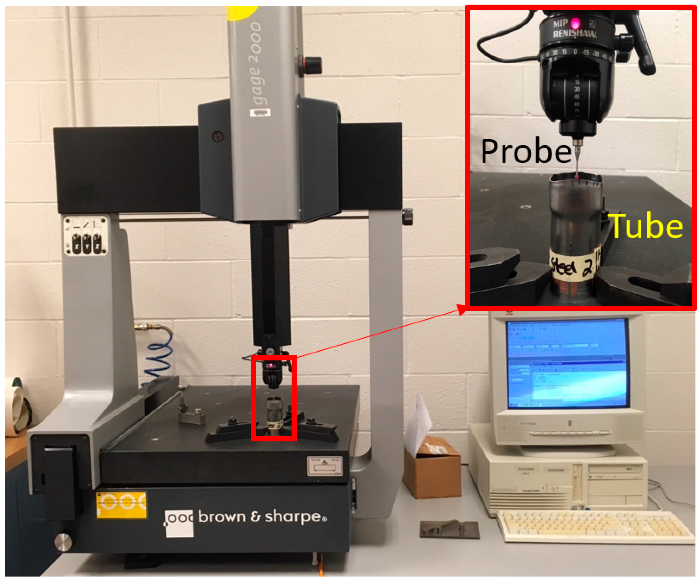
Figure 3.
Force displacement curves: (a) SQ-ST and SQ-T; (b) RT-ST in Z direction; (c) RT-T in Z direction; (d) RT-ST in X and Y direction; and (e) RT-T in X and Y direction.
Figure 3.
Force displacement curves: (a) SQ-ST and SQ-T; (b) RT-ST in Z direction; (c) RT-T in Z direction; (d) RT-ST in X and Y direction; and (e) RT-T in X and Y direction.

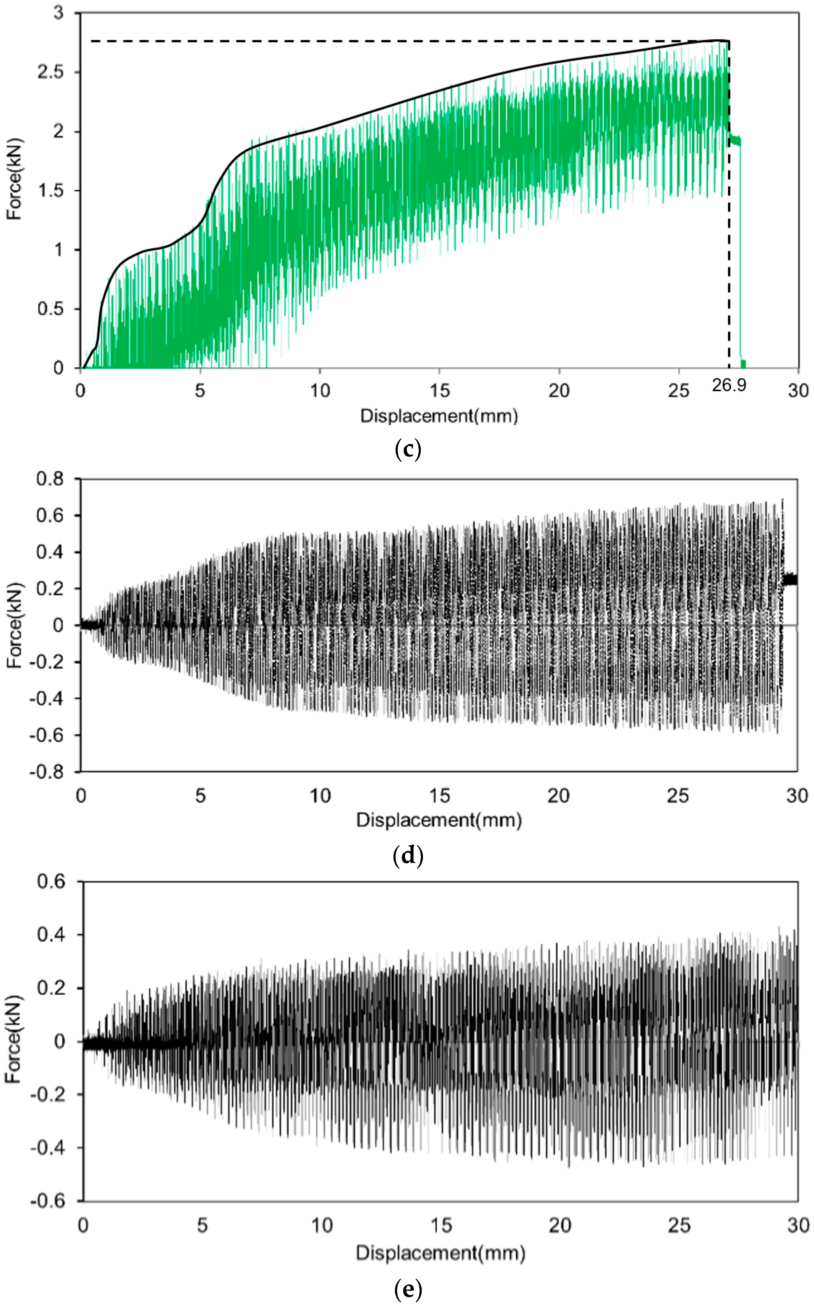
Figure 4.
Deformed square tubes: (a) From left to right: RT-ST, RT-T, SQ-ST and SQ-T (b) Top sectional quarter square profile.
Figure 4.
Deformed square tubes: (a) From left to right: RT-ST, RT-T, SQ-ST and SQ-T (b) Top sectional quarter square profile.
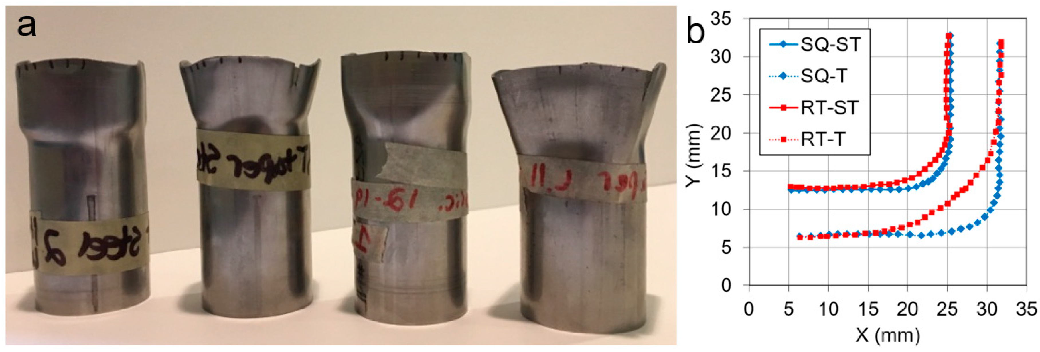
Figure 5.
Wall thicknesses measured at points along tube wall.
© 2017 by the authors. Licensee MDPI, Basel, Switzerland. This article is an open access article distributed under the terms and conditions of the Creative Commons Attribution (CC BY) license (http://creativecommons.org/licenses/by/4.0/).
Share and Cite
MDPI and ACS Style
Seibert, H.; Petrut, L.; Nikhare, C.P. Tube Forming Using a Reuleaux Triangle. J. Manuf. Mater. Process. 2017, 1, 16. https://doi.org/10.3390/jmmp1020016
AMA Style
Seibert H, Petrut L, Nikhare CP. Tube Forming Using a Reuleaux Triangle. Journal of Manufacturing and Materials Processing. 2017; 1(2):16. https://doi.org/10.3390/jmmp1020016
Chicago/Turabian StyleSeibert, Hayden, Laurentiu Petrut, and Chetan P. Nikhare. 2017. "Tube Forming Using a Reuleaux Triangle" Journal of Manufacturing and Materials Processing 1, no. 2: 16. https://doi.org/10.3390/jmmp1020016