Characterization and Processing Behavior of Heated Aluminum-Polycarbonate Composite Build Plates for the FDM Additive Manufacturing Process

 ,
,
Abstract
:
1. Introduction
2. Build Plate Configurations for FDM
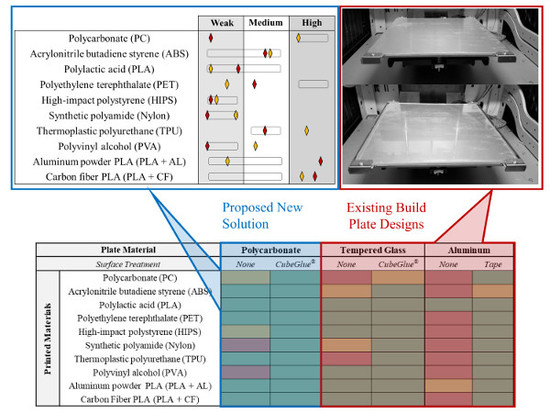
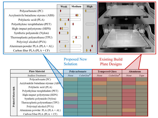
2.1. Brief Overview of Common Solutions
2.2. Proposed Al-PC Composite Build Plate Design
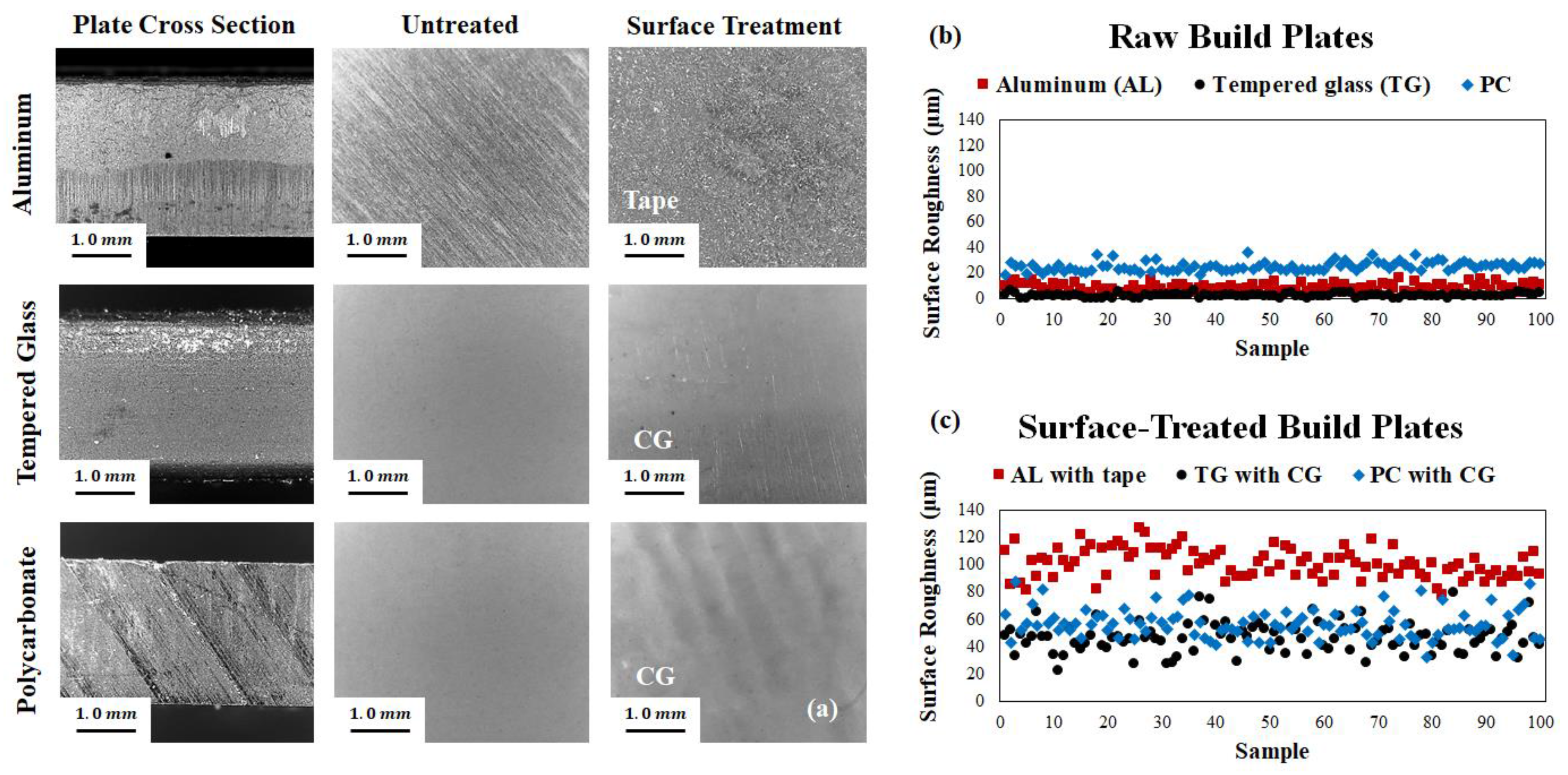
2.3. Surface Profile Comparison Experiment
3. FDM Materials: PC Bonding and Properties
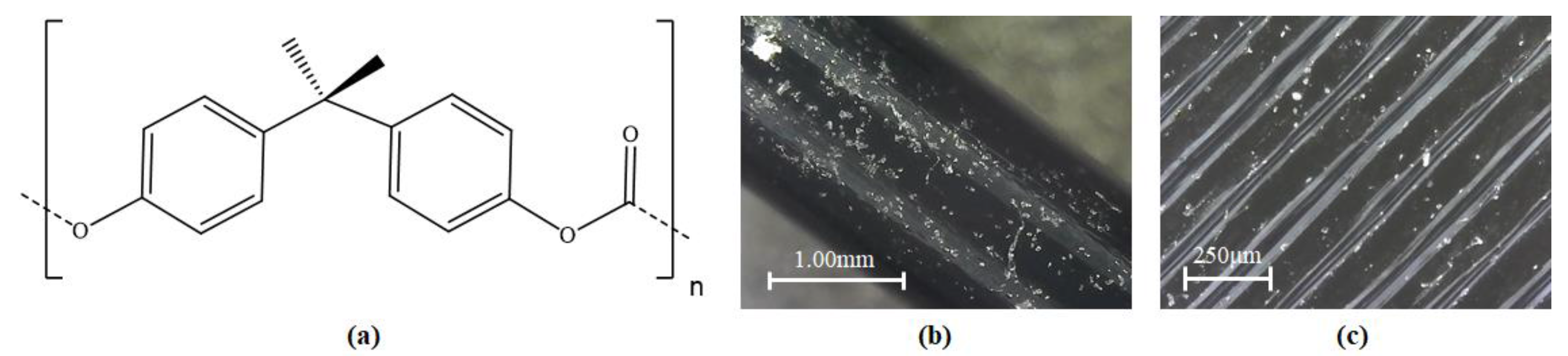
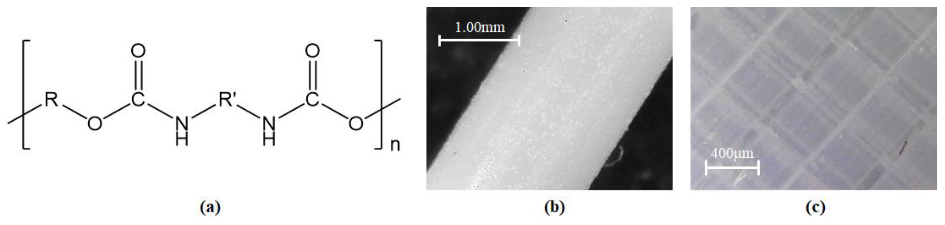
3.1. Polycarbonate (PC)
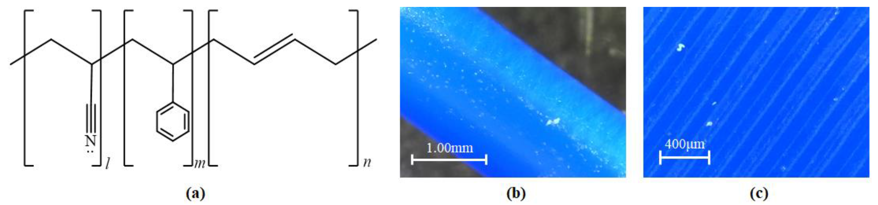
3.2. Acrylonitrile Butadiene Styrene (ABS)
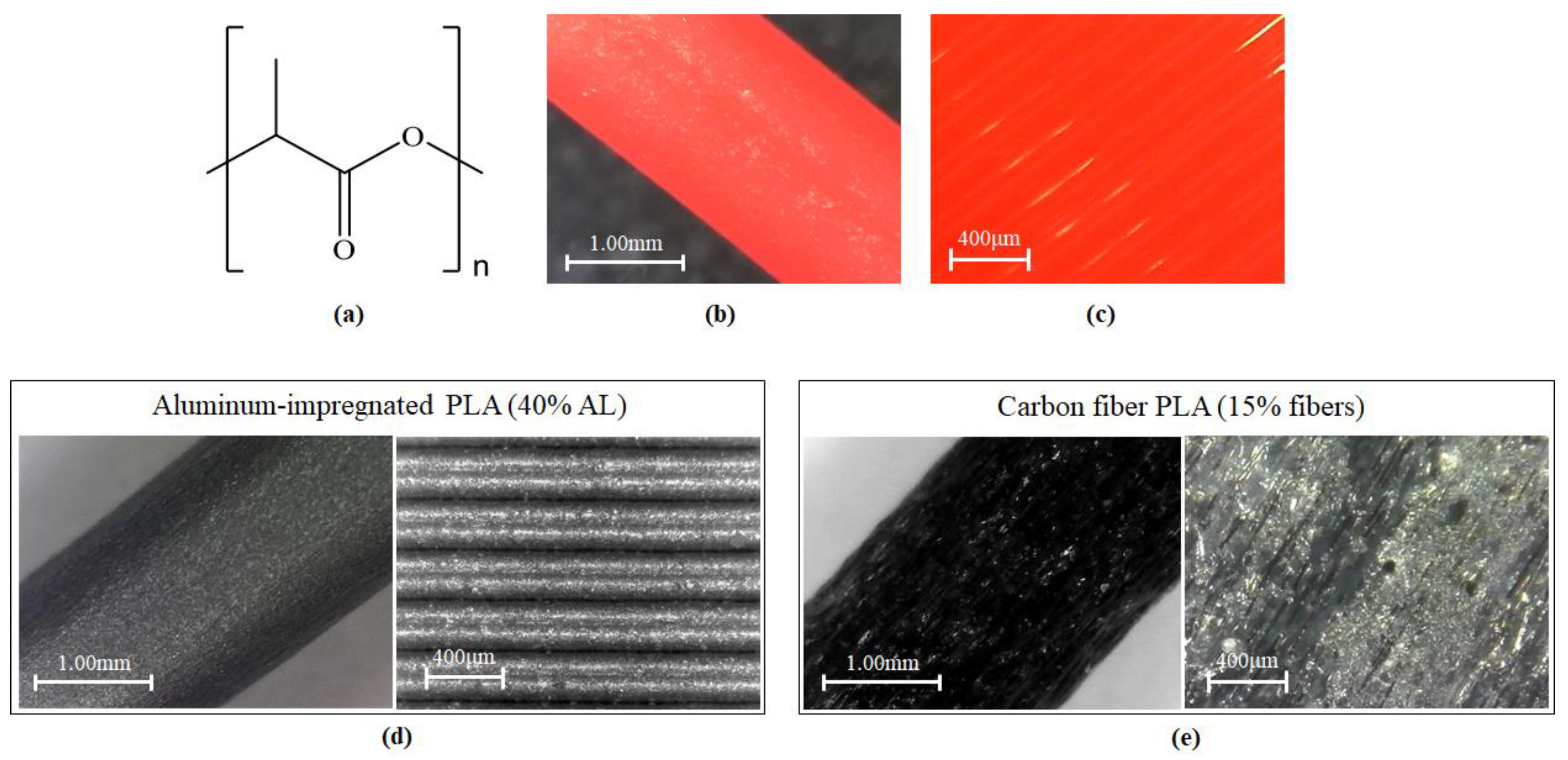
3.3. Polylactic Acid (PLA) and Blends
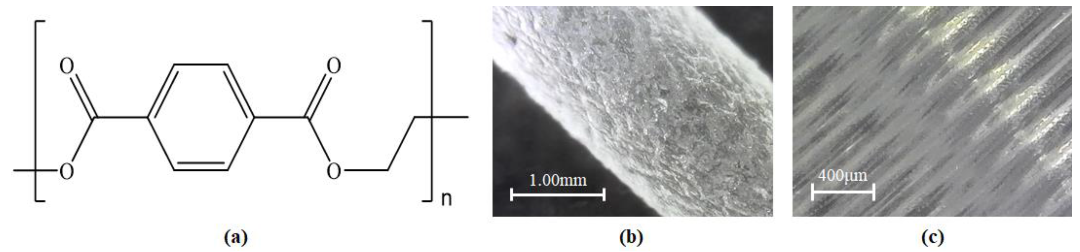
3.4. Polyethylene Terephthalate (PET)
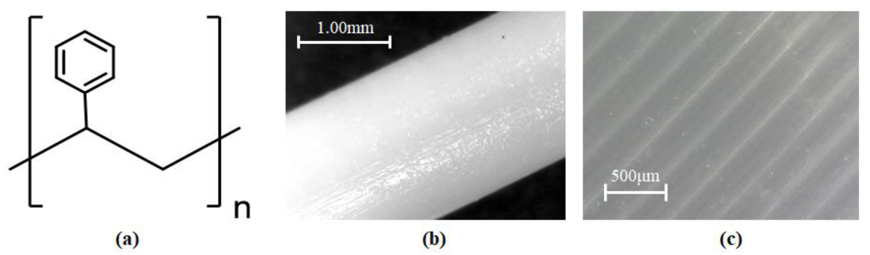
3.5. High-Impact Polystyrene (HIPS)
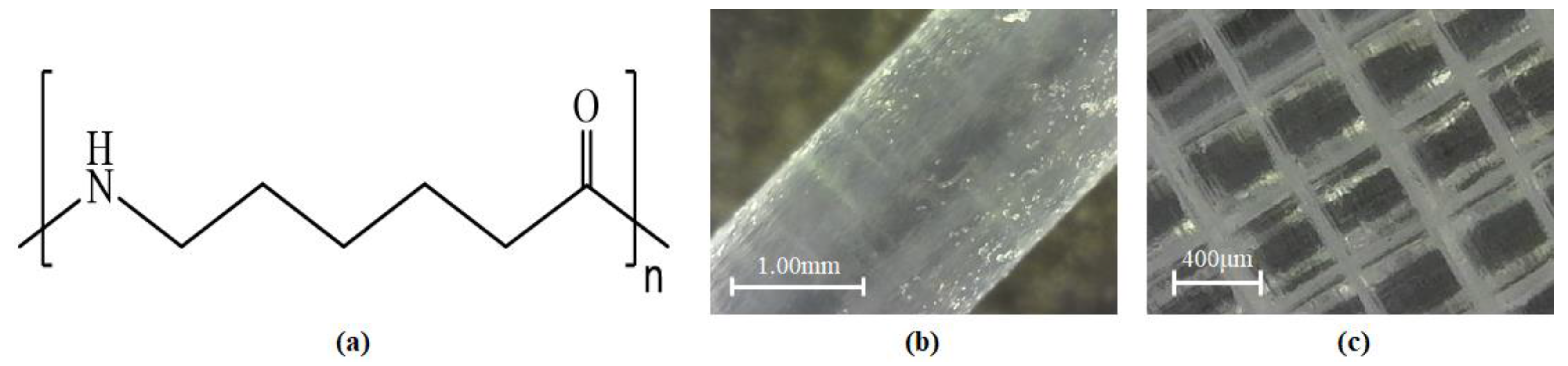
3.6. Synthetic Polyamide (Nylon)
3.7. Thermoplastic Polyurethane (TPU)
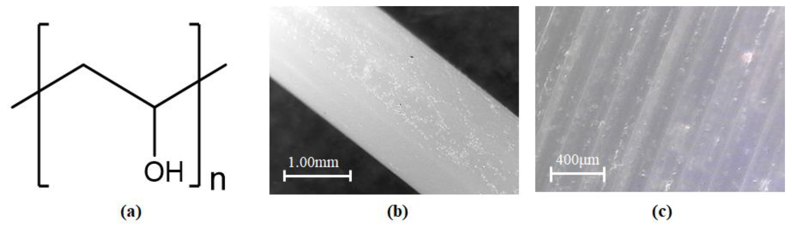
3.8. Polyvinyl Alcohol (PVA)
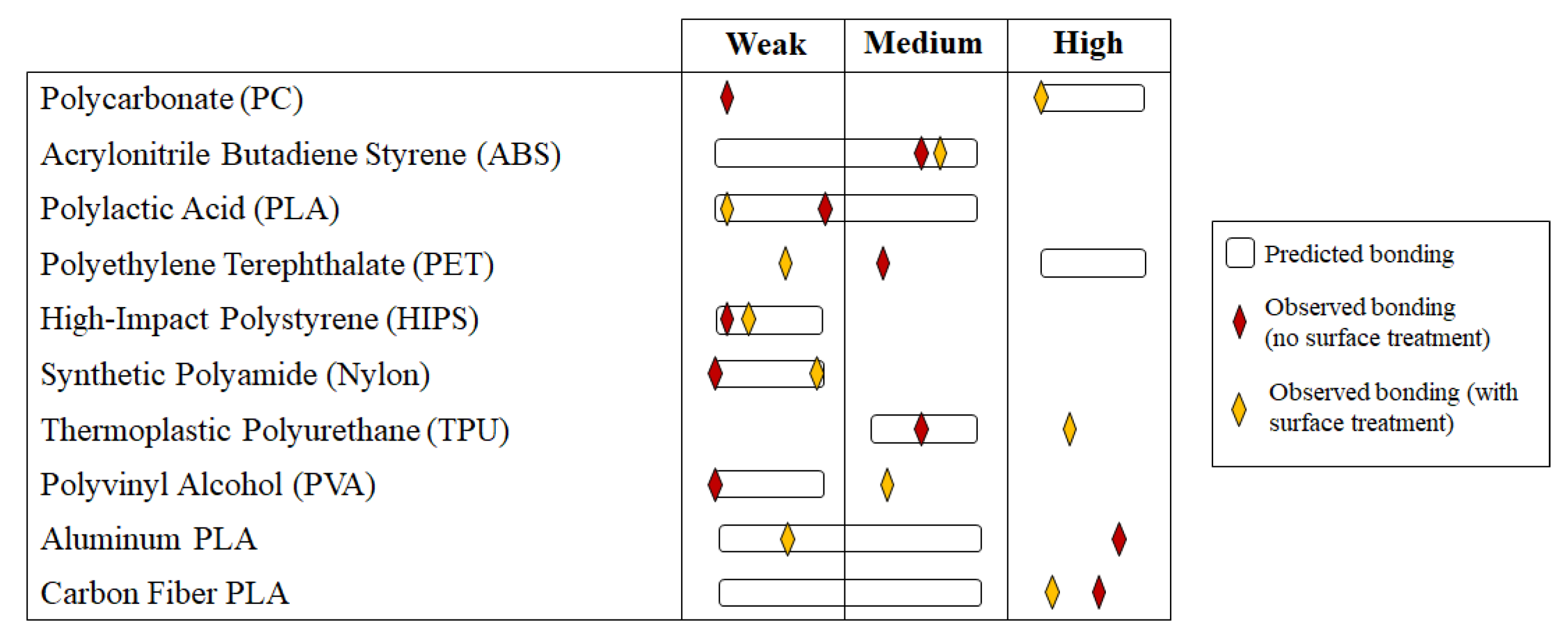
3.9. Summary of Bonding Predictions
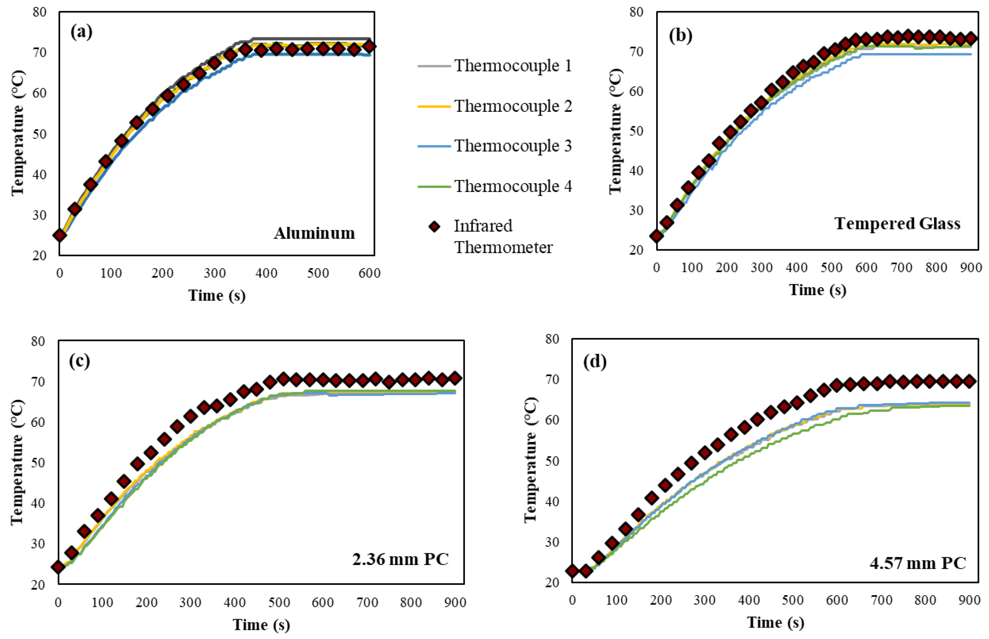
4. Thermal Behavior of AL-PC Composite Build Plate
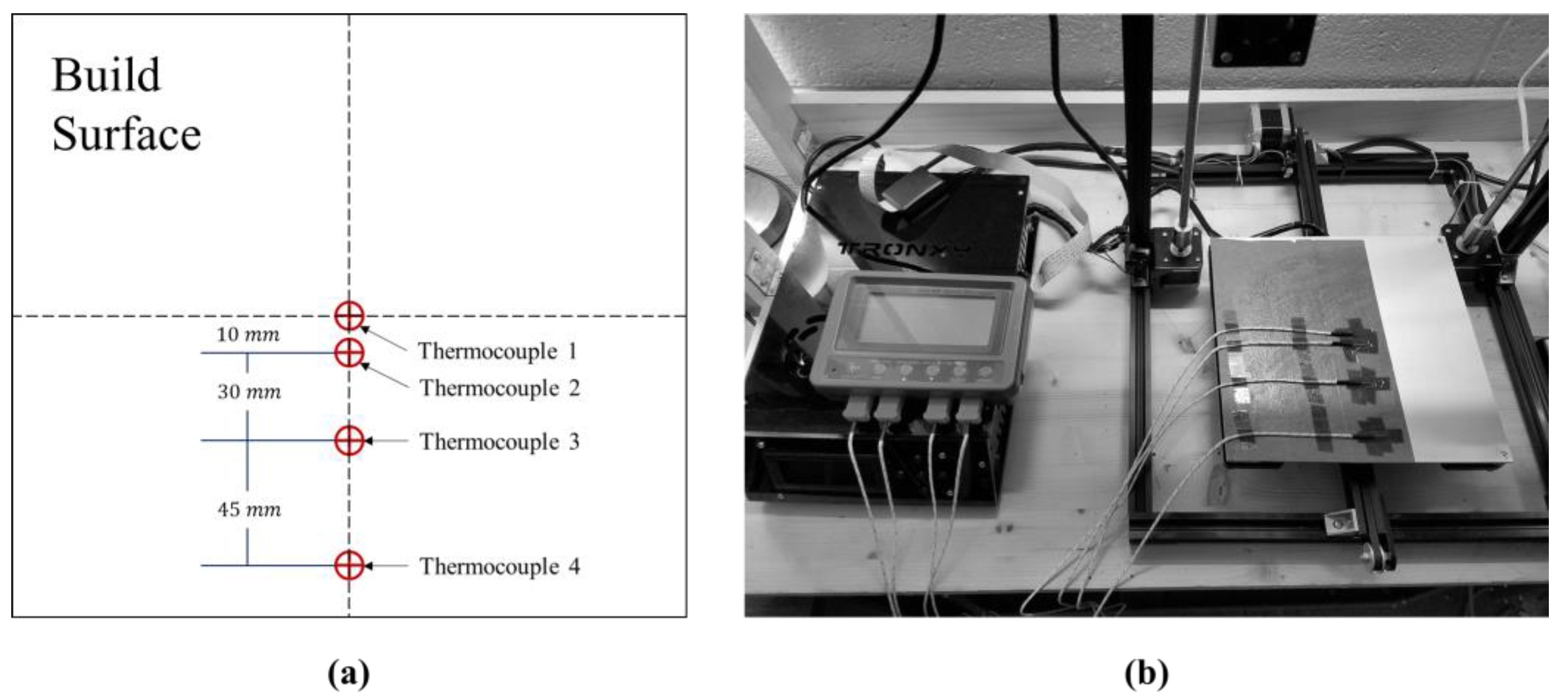
4.1. Experimental Heat Loss Characterization
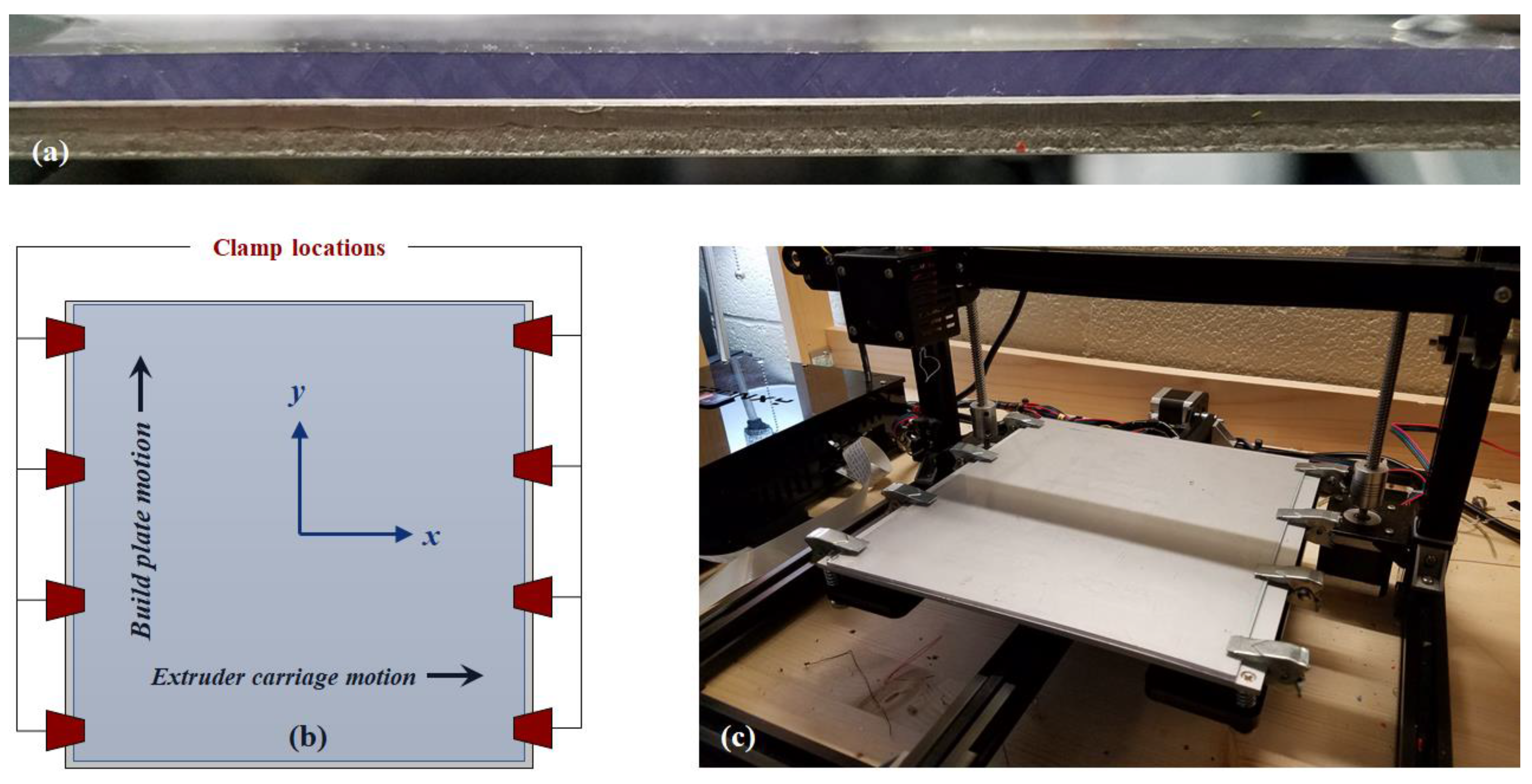
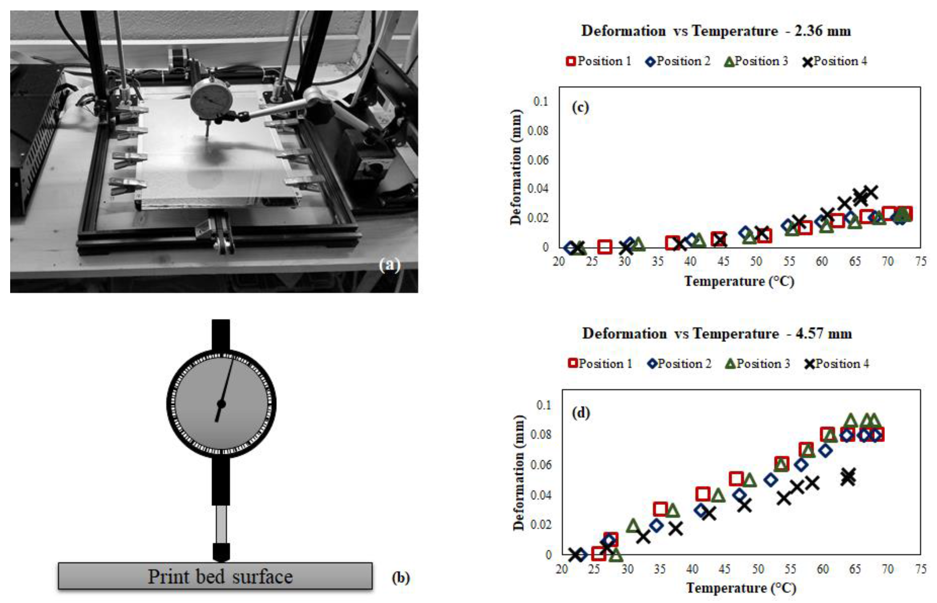
4.2. Deformation and Warping Behavior Characterization
5. Printing Behavior of the AL-PC Composite Build Plate
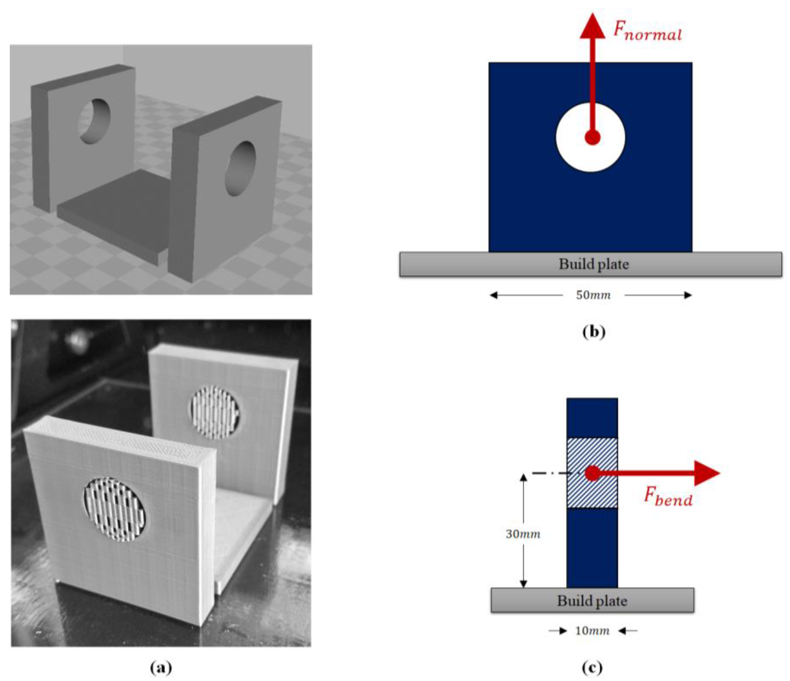
5.1. Experimental Setup and Parameter Selection
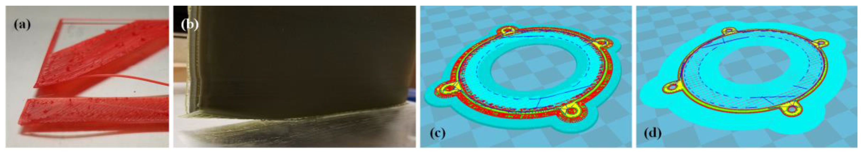
5.2. Experimental Results and Discussion
5.3. Preliminary Nozzle Deposition Heat Effects Study
6. Printability Comparison Study
7. Discussion of Results
8. Conclusions
Acknowledgments
Author Contributions
Conflicts of Interest
Appendix A. Table of Material Properties

| Material | Young’s Modulus (GPa) | Yield Strength (MPa) | Elongation at Break (%) | Thermal Expansion (μm/m °C) | Glass Temperature (°C) | Thermal Conductivity (W/m °C) | References |
|---|---|---|---|---|---|---|---|
| PC B | 2.21 | 72.4 | 100 | 70.2 | 145.0 | 0.19 | [39] |
| PC P | 2.31 | 65.0 | 12.2 | - | 144.0 | - | [93] |
| ABS B | 2.26 | 43.5 | 24 | 89.0 | 108.0 | 0.18 | [94,95] |
| ABS P | 2.00 | 34.8 | 32 | 89.0 | 96.0 | 0.20 | [96,97] |
| PLA B | 2.96 | 58.4 | 10 | 80.0 | 70.0 | 0.20 | [98,99,100] |
| PLA P | 3.50 | 61.0 | 3.5 | - | 60.0 | - | [97,101] |
| PET B | 2.76 | 59.3 | 70 | 39.0 | 82.0 | 0.18 | [99,102,103] |
| PET P | 0.80 | 43.0 | 9 | - | - | - | [104,105,106] |
| HIPS B | 1.90 | 32.0 | 40 | 80.0 | 100.0 | 0.22 | [107] |
| HIPS P | 1.55 | 22.0 | 50 | 80.0 | 100.0 | - | [108] |
| Nylon B | 2.70 | 55.0 | 67 | 84.0 | 40.0 | 0.25 | [109] |
| Nylon P | - | 36.0 | 186 | 62.0 | - | - | [110] |
| TPU B | None | 31.0 | 450 | - | <0 | - | [111] |
| TPU P | None | 40.0 | 702 | - | <0 | - | [14] |
| PVA B | - | 54.0 | 150 | - | - | - | [112] |
| PVA P | 3.90 | 78.0 | 10 | 75.0 | 60.2 | 0.31 | [113,114,115] |
| PLA + AL | - | - | - | - | - | - | - |
| PLA + CF | - | 45.5 | 32 | - | - | - | [116] |
References
- Crump, S.S. Apparatus and Method for Creating Three-Dimensional Objects. U.S. Patent 5,121,329, 9 June 1992. [Google Scholar]
- Turner, B.N.; Strong, R.; Gold, S.A. A review of melt extrusion additive manufacturing processes: I. Process design and modelling. Rapid Prototyp. J. 2014, 20, 192–204. [Google Scholar] [CrossRef]
- Mohamed, O.A.; Masoon, S.H.; Bhowmik, J.L. Optimization of fused deposition modeling process parameters: A review of current research and future prospects. Adv. Manuf. 2015, 3, 42–53. [Google Scholar] [CrossRef]
- Mohamed, O.A.; Masoon, S.H.; Bhowmik, J.L. Analytical Modelling and Optimization of the Temperature-Dependent Dynamic Mechanical Properties of Fused Deposition Fabricated Parts Made of PC-ABS. Materials 2016, 9, 895. [Google Scholar] [CrossRef] [PubMed]
- Sood, A.K.; Ohdar, R.; Mahapatry, S. Parametric appraisal of mechanical property of fused deposition modeling processed parts. Mater. Des. 2010, 31, 287–295. [Google Scholar] [CrossRef]
- Ryan, T.; Hubbard, D. 3-D Printing Hazards: Literature Review & Preliminary Hazard Assessment. Prof. Saf. 2016, 6, 56–62. [Google Scholar]
- TBERG. Enclosure Performance: Ultrafine Particles (UFPs) and Volatile Organic Compounds (VOCs) Removal Efficiency of Desktop 3D Printer Enclosures; Report 102/001; The Built Environment Research Group, Illinois Institute of Technology: Chicago, IL, USA, 2017; Available online: http://built-envi.com/wp-content/uploads/Report_UPBox_ABS_White_Clean.pdf (accessed on 2 January 2018).
- Zontek, T.L.; Ogle, B.R.; Jankovic, J.T.; Hollenbeck, S.M. An exposure assessment of desktop 3D printing. J. Chem. Health Saf. 2017, 2, 15–25. [Google Scholar] [CrossRef]
- McDonnel, B.; Guzman, X.J.; Dolack, M.; Simpson, T.W.; Cimbala, J. 3D Printing in the Wild: A Preliminary Investigation or Air Quality in College Maker Spaces. In Proceedings of the 2016 Solid Freeform Fabrication Conference, Austin, TX, USA, 8–10 August 2016; pp. 2457–2469. [Google Scholar]
- Olsson, A.; Hellsing, M.S.; Rennie, A.R. New possibilities using additive manufacturing with materials that are difficult to process and with complex structures. Phys. Scr. 2017, 92, 053002. [Google Scholar] [CrossRef]
- Sandoval, J. Modeling Abrasive Wear of a 3D Printer Extruder Drive Mechanism. Bachelor's Thesis, Massachusetts Institute of Technology, Cambridge, MA, USA, 8 July 2016. [Google Scholar]
- Trimmer, B.; Lewis, J.A.; Shepherd, R.F.; Lipson, H. 3D Printing Soft Materials: What is Possible? Soft Robot. 2015, 2, 3–6. [Google Scholar] [CrossRef]
- Arnitel® ID. Overcoming 3D Printing Speed Limitations of Flexible Soft Plastics with Arnitel® ID. Available online: https://www.dsm.com/content/dam/dsm/arnitel/en_US/documents/Arnitel%20ID%203D%20printing.pdf (accessed on 22 January 2018).
- Xiao, J.; Gao, Y. The manufacture of 3D printing of medical grade TPU. Prog. Addit. Manuf. 2017, 2, 117–123. [Google Scholar] [CrossRef]
- Zhang, W.; Wu, A.S.; Sun, J.; Quan, Z.; Gu, B.; Sun, B.; Cotton, C.; Heider, D.; Chou, T.-W. Characterization of residual stress and deformation in additively manufactured ABS polymer and composite specimens. Compos. Sci. Technol. 2017, 150, 102–110. [Google Scholar] [CrossRef]
- Tymrak, B.M.; Kreiger, M.; Pearce, J.M. Mechanical properties of components fabricated with open-source 3-D printers under realistic environmental conditions. Mater. Des. 2014, 58, 242–246. [Google Scholar] [CrossRef]
- Choi, Y.-H.; Kim, C.-M.; Jeong, H.-S.; Youn, J.-H. Influence of Bed Temperature on Heat Shrinkage Shape Error in FDM Additive Manufacturing of the ABS-Engineering Plastic. World J. Eng. 2016, 4, 186–192. [Google Scholar] [CrossRef]
- Xu, Y. Experimental Study of ABS Material Shrinkage and Deformation Based on Fused Deposition Modeling. MATEC Web Conf. 2016, 67, 03039. [Google Scholar] [CrossRef]
- Afinia.com. Four Ways to Prepare the Printing Surface of Your 3D Printer. Available online: http://www.afinia.com/afinia-downloads/Afinia-Preparing-The-Print-Surface.pdf (accessed on 20 December 2017).
- Makerbot. Replicator User Manual. Available online: http://download.makerbot.com/replicator/MB_Replicator_UserManual.pdf (accessed on 20 December 2017).
- 3D Systems. Cube 3rd Generation Personal Printer User Manual. Available online: http://cubify.s3.amazonaws.com/public/cube3/guides/cube3_user_guide.pdf (accessed on 20 December 2017).
- Prusa. 3D Printing Handbook. Available online: https://www.prusa3d.cz/downloads/manual/prusa3d_manual_175_en.pdf (accessed on 20 December 2017).
- Dynamism.com. TonerPlastics ABS 3D Filament Data Sheet. Available online: https://www.dynamism.com/download/2016/tonerplastics-ABS-SDS.pdf (accessed on 20 December 2017).
- Ultimaker. Ultimaker 2 User Manual. Available online: http://fab.cba.mit.edu/content/tools/ultimaker2/Ultimaker_2_User_Manual_V1.08.pdf (accessed on 20 December 2017).
- Pinshape.com. 4 3D Printer Surface Materials for Better Adhesion! Available online: https://pinshape.com/blog/4–3d-printer-bed-surface-materials-for-better-adhesion/ (accessed on 20 December 2017).
- Minetola, P.; Iuliano, L.; Marchiandi, G. Benchmarking of FDM machines through part quality using IT grades. Procedia CIRP 2016, 41, 1027–1032. [Google Scholar] [CrossRef]
- Espalin, D.; Ramirez, J.; Medina, F.; Wicker, R. Multi-Material, Multi-Technology FDM System. In Proceedings of the 2012 Solid Freeform Fabrication Conference, Austin, TX, USA, 6–8 August 2012; pp. 828–835. [Google Scholar]
- Alabdullah, F. Fused Deposition Modeling (FDM) Mechanism. Int. J. Sci. Eng. Res. 2016, 7, 41–43. [Google Scholar]
- Kumar, G.P.; Regalla, S.P. Optimization of Support Material and Build Time in Fused Deposition Modeling (FDM). Appl. Mech. Mater. 2012, 110, 2245–2251. [Google Scholar] [CrossRef]
- Gajdos, I.; Slota, J. Influence of Printing Conditions on Structures in FDM Prototypes. Tech. Gaz. 2013, 20, 231–236. [Google Scholar]
- Seigel, J.E.; Erb, D.C.; Ehrenberg, I.M.; Ehrenberg, I.M.; Jain, P.; Sarma, S.E. Local Viscosity Control Printing for High-Throughput Additive Manufacturing of Polymers. 3D Print. Addit. Manuf. 2016, 3, 252–261. [Google Scholar] [CrossRef]
- BuildTak.com. Available online: https://www.buildtak.com/ (accessed on 20 December 2017).
- LokBuild.com. Available online: http://www.lokbuild.com/ (accessed on 20 December 2017).
- Instructables.com. Reusable Print Beds. Available online: http://www.instructables.com/id/1-Reusable-Print-Beds/ (accessed on 20 December 2017).
- Adafruit.com. 3D Printing on PRINTinZ: Flexible Build Plate. Available online: https://cdn-learn.adafruit.com/downloads/pdf/3d-printing-on-ninjaplate-flexible-build-plate.pdf (accessed on 20 December 2017).
- 3D Systems. Magic Cube™ Glue Materials Safety Data Sheet. Available online: http://cubify.s3.amazonaws.com/Printers/Safety%20data%20sheets/cube1_sds_magic_cube_glue_english_eu.pdf (accessed on 22 January 2018).
- Tummala, P.; Turner, P.S.; Johnson, M.A. Adhesive for 3D Printing. U.S. Patent No. 9,757,881B2, 12 September 2017. [Google Scholar]
- Curbell Plastics. Polycarbonate Datasheet. Available online: http://www.masteran.co.il/uploads/PDF/polycarbonate-eng-datasheet-curbell.pdf (accessed on 23 January 2018).
- Gplastics.com. Polycarbonate Datasheet. Available online: http://www.gplastics.com/pdf/polycarbonate.pdf (accessed on 22 December 2017).
- Nunez, E.E.; Polycarpou, A.A. The effect of surface roughness on the transfer of polymer films under unlubricated testing conditions. Wear 2015, 326, 74–83. [Google Scholar] [CrossRef]
- Douglas, J.F. How Does Surface Roughness Affect Polymer-Surface Interactions? Macromolecules 1989, 22, 3707–3716. [Google Scholar] [CrossRef]
- Baumgartner, A.; Muthukumar, M. Effects of surface roughness on absorbed polymers. J. Chem. Phys. 1991, 94, 4062–4070. [Google Scholar] [CrossRef]
- Locktite. Design Guide for Bonding Plastics. 2011, Volume 6. Available online: http://na.henkel-adhesives.com/us/content_data/397189_LT2197_Plastic_Guide_v6_LR.pdf (accessed on 27 December 2017).
- Ghumatkar, A.; Budhe, S.; Sekhar, R.; Banea, M.D.; de Barros, S. Influence of Adherend Surface Roughness on the Adhesive Bond Strength. Latin Am. J. Solids Struct. 2016, 13, 2357–2370. [Google Scholar] [CrossRef]
- Aydin, S.; Solmaz, M.Y.; Turgut, A. The effects of adhesive thickness, surface roughness and overlap distance on joint strength in prismatic plug-in joints attached with adhesive. Int. J. Phys. Sci. 2012, 7, 2580–2586. [Google Scholar]
- Park, R.; Jang, J. The effect of surface roughness on the adhesion properties of ceramic/hybrid FRP adhesively bonded systems. J. Adhes. Sci. Technol. 1998, 12, 713–729. [Google Scholar] [CrossRef]
- Hareesh, K.; Sen, P.; Bhat, R.; Bhargavi, R.; Geetha, G. Nair, Sangappa, Ganesh Sanjeev. Proton and alpha particle induced changes in thermal and mechanical properties of Lexan polycarbonate. Vacuum 2013, 91, 1–6. [Google Scholar] [CrossRef]
- Caporossi, L.; Papaleo, B. Bisphenol A and Metabolic Diseases: Challenges for Occupational Medicine. Int. J. Environ. Res. Public Health 2017, 14, 959. [Google Scholar] [CrossRef] [PubMed]
- Idris, A.; Man, Z.; Maulud, A.S.; Khan, M.S. Effects of Phase Separation Behavior on Morphology and Performance of Polycarbonate Membranes. Membranes 2017, 7, 21. [Google Scholar] [CrossRef] [PubMed]
- Xu, Y.; Gao, T.; Wang, J.; Zhang, W. Experimentation and Modeling of the Tension Behavior of Polycarbonate at High Strain Rates. Polymers 2016, 8, 63. [Google Scholar] [CrossRef]
- Narijauskaite, B.; Palevicius, A.; Gaidys, R.; Janušas, G.; Sakalys, R. Polycarbonate as an Elasto-Plastic Material Model for Simulation of the Microstructure Hot Imprint Process. Sensors 2013, 13, 11229–11242. [Google Scholar] [CrossRef] [PubMed]
- Sivasankar, B. Engineering Chemistry; Tata McGraw-Hill: New Delhi, India, 2008. [Google Scholar]
- Duman, A.N.; Yilbar, B.S.; Pirim, H.; Ali, H. Texture Analysis of Hyrophobic Polycarbonate and Polydimethylsiloxane Surfaces via Persistent Homology. Coatings 2017, 7, 139. [Google Scholar] [CrossRef]
- Cantrell, J.T.; Rohde, S.; Damiani, D.; Gurnani, R.; DiSandro, L.; Anton, J.; Young, A.; Jerez, A.; Steinbach, D.; Kroese, C.; et al. Experimental characterization of the mechanical properties of 3D-printed ABS and polycarbonate parts. Rapid Prototyp. J. 2017, 23, 811–824. [Google Scholar] [CrossRef]
- Barwinkel, S.; Seidel, A.; Hobeika, S.; Hufen, R.; Mörl, M.; Altstädt, V. Morphology Formation in PC/ABS Blends during Thermal Processing and the Effects of the Viscosity Ratio of Blend Partners. Materials 2016, 9, 659. [Google Scholar] [CrossRef] [PubMed]
- Ahn, S.-H.; Montero, M.; Odell, D.; Roundy, S.; Wright, P.K. Anisotropic material propertied of fused deposition modeling ABS. Rapid Prototyp. J. 2002, 8, 248–257. [Google Scholar] [CrossRef]
- Olivera, S.; Muralidhara, H.B.; Venkatesh, K.; Gopalakrishna, K.; Vivek, C.S. Plating on acrylonitrile-butadiene-styrene (ABS): A review. J. Mater. Sci. 2016, 51, 3657–3674. [Google Scholar] [CrossRef]
- Tiganis, B.E.; Burn, L.S.; Davis, P.; Hill, A.J. Thermal degradation of acrylonitrile-butadiene-styrene (ABS) blends. Polym. Degrad. Stab. 2002, 76, 425–434. [Google Scholar] [CrossRef]
- Suzuki, M.; Wilkie, C.A. The thermal degradation of acrylonitrile-butadiene-styrene terpolymer as studied by TGA/FTIR. Polym. Degrad. Stab. 1995, 47, 217–221. [Google Scholar] [CrossRef]
- Lim, L.T.; Auru, R.; Rubino, M. Processing Technologies for Poly(lactic) Acid. Prog. Polym. Sci. 2008, 33, 820–852. [Google Scholar] [CrossRef]
- Cuiffo, M.A.; Snyder, J.; Elliot, A.M.; Romero, N.; Kannan, S.; Halada, G.P. Impact of the Fused Deposition Modeling (FDM) Printing Process on Polylactic Acid (PLA) Chemistry and Structure. Appl. Sci. 2017, 7, 579. [Google Scholar] [CrossRef]
- Drumright, R.E.; Gruber, P.R.; Henton, D.E. Polylactic Acid Technology. Adv. Mater. 2000, 12, 1841–1846. [Google Scholar] [CrossRef]
- Phuong, V.T.; Gigante, V.; Aliotta, L.; Coltelli, M.B.; Cinelli, P.; Lazzeri, A. Reactively extruded ecocomposites based on poly(lactic acid)/bisphenol A polycarbonate blends reinforced with regenerated cellulose microfibers. Compos. Sci. Technol. 2017, 139, 127–137. [Google Scholar] [CrossRef]
- Wang, Y.; Chiao, S.M.; Hung, T.-F.; Yang, S.-Y. Improvements in toughness and heat resistance of poly(lactic acid)/polycarbonate blend through twin-screw blending: Influence of the compatibilizer type. J. Appl. Polym. Sci. 2012, 125, E402–E412. [Google Scholar] [CrossRef]
- Licciardello, A.; Auditore, A.; Samperi, F.; Puglisi, C. Surface evolution of polycarbonate/polyethylene terephthalate blends induced by thermal treatments. Appl. Surf. Sci. 2003, 203–204, 556–560. [Google Scholar] [CrossRef]
- Beeva, D.A.; Borisov, A.K.; Mikitaev, M.K.; Beev, A.A.; Barokova, E.B. Controlling the barrier properties of polyethylene terephthalate. A review. Int. Polym. Sci. Technol. 2015, 42, 45–52. [Google Scholar]
- Feitor, M.C.; Alves, C., Jr.; Bezerra, C.M.; de Sousa, R.R.M.; de Carvalho Costa, T.H. Evaluation of Aging in Air of Poly (Ethylene Terephthalate) in Oxygen Plasma. Mater. Res. 2015, 18, 891–896. [Google Scholar] [CrossRef]
- Blanco, I.; Cicala, G.; Restuccia, C.L.; Latteri, A.; Battiato, S.; Scamporrino, A.; Samperi, F. Role of 2-hydroxyethyl end group on the thermal degradation of poly(ethylene terephthalate) and reactive melt mixing of poly(ethylene terephthalate)/poly(ethylene naphthalate) blends. Polym. Eng. Sci. 2012, 52, 2498–2505. [Google Scholar] [CrossRef]
- Mitchell, P. Tool and Manufacturing Engineers Handbook: A Reference for Manufacturing Engineers, Managers, and Technicians; Society of Manufacturing Engineers: Dearborn, MI, USA, 1996; Volume 8. [Google Scholar]
- Perepechko, I. Low Temperature Properties of Polymers; Franklin Book Company: Elkins Park, Philadelphia, PA, USA, 1994. [Google Scholar]
- Masood, M.T.; Heredia-Guerrero, J.A.; Ceseracciu, L.; Palazon, F.; Athanassiou, A.; Bayer, I.S. Superhydrophobic High Impact Polystyrene (HIPS) Nanocomposites with Wear Abrasion Resistance. Chem. Eng. J. 2017, 322, 10–21. [Google Scholar] [CrossRef]
- Hobbs, S.Y. The effect of rubber particle size on the impact properties of high impact polystyrene (HIPS) blends. Polym. Sci. Eng. 1986, 26, 74–81. [Google Scholar] [CrossRef]
- Fouda, I.; Shabana, H. Opto-structural characterization of proton (3MeV) irradiated polycarbonate and polystyrene. Polym. Int. 1999, 48, 198–204. [Google Scholar] [CrossRef]
- Vilaplana, F.; Ribes-Greus, A.; Karlsson, S. Degradation of recycled high-impact polystyrene. Simulation by reprocessing and thermos-oxidation. Polym. Degrad. Stab. 2006, 91, 2163–2170. [Google Scholar] [CrossRef]
- Ohishi, H.; Ikehara, T.; Nishi, T. Phase morphology of polystyrene-polyarylate block copolymer/polycarbonate blends and their application to disk substrates. J. Appl. Polym. Sci. 2001, 82, 2566–2582. [Google Scholar] [CrossRef]
- Cho, J.W.; Paul, D.R. Nylon 6 nanocomposites by melt compounding. Polymer 2001, 42, 1083–1094. [Google Scholar] [CrossRef]
- Fornes, T.D.; Yoon, P.J.; Keskkula, H.; Paul, D.R. Nylon 6 nanocomposites: The effect of matrix molecular weight. Polymer 2001, 42, 9929–9940. [Google Scholar] [CrossRef]
- Cheng, F.; Li, H.; Chen, D. Properties of Compatibilized Nylon 6/ABS Polymer Blends. J. Macromol. Sci. Part B Phys. 2006, 45, 557–561. [Google Scholar] [CrossRef]
- Kyulavska, M.; Bryaskova, R.; Bozukova, D.; Mateva, R.P. Synthesis, structure and behavior of new polycaprolactam copolymers based on poly (ethylene oxide)–poly (propylene oxide)–poly(ethylene oxide) macroactivators derived from Pluronic block copolymers. J. Polym. Res. 2014, 21, 471. [Google Scholar] [CrossRef]
- Borggreve, R.J.M.; Gaymans, R.J.; Schuijer, J.; Ingen Housz, J.F. Brittle-tough transition on nylon-rubber blends: Effect of rubber concentration and particle size. Polymer 1987, 28, 1489–1496. [Google Scholar] [CrossRef]
- Gattiglia, E.; Turturro, A.; Pedemonte, E. Blends of polyamide 6 with bisphenol-A polycarbonate. I. Thermal properties and compatibility aspects. J. Appl. Polym. Sci. 1989, 38, 1807–1818. [Google Scholar] [CrossRef]
- Wang, M.; Yuan, G.; Han, C.C. Reaction process in polycarbonate/polyamide bilayer film and blend. Polymer 2013, 54, 3612–3619. [Google Scholar] [CrossRef]
- Romin, R.; Nakason, C.; Thitithammawong, A. Blends of Thermoplastic Polyurethanes and Polyamide 12: Structure, Molecular Interactions, Relaxation, and Mechanical Properties. Adv. Mater. Res. 2012, 626, 58–61. [Google Scholar] [CrossRef]
- Alves, P.; Coelho, J.F.J.; Haack, J.; Rota, A.; Bruinink, A.; Gil, M.H. Surface modification and characterization of thermoplastic polyurethane. Eur. Polym. J. 2009, 45, 1412–1419. [Google Scholar] [CrossRef]
- Lu, Q.-W.; Macosko, C.W. Comparing the compatibility of various functionalized polypropylenes with thermoplastic polyurethane (TPU). Polymer 2004, 45, 1981–1991. [Google Scholar] [CrossRef]
- Fakirov, S. Handbook of Condensation Thermoplastic Elastomers; Wiley-VCH: Weinheim, Germany, 2005. [Google Scholar]
- Herrera, M.; Matuschek, G.; Kettrup, A. Thermal degradation of thermoplastic polyurethane elastomers (TPU) based on MDI. Polym. Degrad. Stab. 2002, 78, 323–331. [Google Scholar] [CrossRef]
- Rowe, A.A.; Tajvidi, M.; Gardner, D.J. Thermal stability of cellulose nanomaterials and their composites with polyvinyl alcohol (PVA). J. Therm. Anal. Calorim. 2016, 126, 1371–1386. [Google Scholar] [CrossRef]
- Mbhele, Z.H.; Salemane, M.G.; van Sittert, C.G.C.E.; Nedeljković, J.M.; Djoković, V.; Luyt, A.S. Fabrication and Characterization of Silver-Polyvinyl Alcohol Nanocomposites. Chem. Mater. 2003, 15, 5019–5024. [Google Scholar] [CrossRef]
- Baker, M.I.; Walsh, S.P.; Schwartz, Z.; Boyan, B.D. A review of polyvinyl alcohol and its uses in cartilage and orthopedic applications. J. Biomed. Mater. Res. Part B Appl. Biomater. 2012, 100B, 1451–1457. [Google Scholar] [CrossRef] [PubMed]
- Bewick, R.; Dunn, D.J. Plastics in Packaging: Western Europe and North America; Smithers Rapra Technology: Billingham, UK, 2002. [Google Scholar]
- Rolando, T.E. Solvent-Free Adhesives; Rapra Technology Limited: Shawbury, Shropshire, UK, 1998. [Google Scholar]
- Vexmatech. Polycarbonate Filament Specifications. Available online: http://vexmatech.com/PC-polycarbonate-FDM-technology-3dprinting-material.html (accessed on 22 January 2018).
- Teststandard.com. ABS Data Sheet. Available online: https://www.teststandard.com/data_sheets/ABS_Data_sheet.pdf (accessed on 22 December 2017).
- Matweb.com. ABS Datasheet. Available online: http://www.matweb.com/search/DataSheet.aspx? MatGUID=3a8afcddac864d4b8f58d40570d2e5aa&ckck=1 (accessed on 22 December 2017).
- 3D Academy “3D Printing. ABS Plastics”. Available online: https://www.3d-alchemy.co.uk/3d-printing-in-abs.html (accessed on 22 January 2018).
- IGEM.org. Comparison of Typical 3D Printing Materials. Available online: http://2015.igem.org/wiki/images/2/24/CamJIC-Specs-Strength.pdf (accessed on 12 November 2017).
- Ulprospector.com. Polylactic Acid (PLA) Typical Properties. Available online: https://plastics.ulprospector.com/generics/34/c/t/polylactic-acid-pla-properties-processing (accessed on 23 December 2017).
- SpecialChem.com. Polymer Properties: Coefficient of Linear Thermal Expansion. Available online: https://omnexus.specialchem.com/polymer-properties/properties/coefficient-of-linear-thermal-expansion. (accessed on 23 December 2017).
- Moldflow. Material Testing Report: NatureWorks PLA. 2007. Available online: https://www.natureworksllc.com/~/media/Technical_Resources/Properties_Documents/PropertiesDocument_7000DMoldFlowReport_pdf.pdf (accessed on 23 December 2017).
- Letcher, T.; Waytashek, M. Material Property Testing of 3D-Printed Specimen in PLA on an Entry-Level 3D Printer. In Proceedings of the ASME 2014 International Mechanical Engineering Congress & Exposition, Montreal, QC, Canada, 14–20 November 2014. Paper # IMECE2014–39379. [Google Scholar]
- Plastic-Products.com. PET (Polyethylene Terephthalate: Typical Property Values. Available online: www.plastic-products.com/part12.htm (accessed on 23 December 2017).
- Kenplas.com. What is PET (PolyEthylene Terephthalate)? Available online: http://www.kenplas.com/project/pet/ (accessed on 23 December 2017).
- TonerPlastics. Tensile Testing Results of Toner Plastics 3D Filament. Available online: http://toner-plastics.com/tesile-testing-results-of-toner-plastics-3d-filament/ (accessed on 23 January 2018).
- Szykiedans, K.; Credo, W.; Osinski, D. Selected mechanical properties of PETG 3-D prints. Procedia Eng. 2017, 177, 455–461. [Google Scholar] [CrossRef]
- Patterson, A.E.; Bahumanyam, P.; Katragadda, R.; Messimer, S.L. Automated assembly of discrete parts using fused deposition modeling. Rapid Prototyp. J. 2018, in press. [Google Scholar] [CrossRef]
- MakeItFrom.com. High Impact Polystyrene (HIPS). Available online: https://www.makeitfrom.com/material-properties/High-Impact-Polystyrene-HIPS (accessed on 23 December 2017).
- Vexmatech. High-Impact Polystyrene Filament. Available online: http://vexmatech.com/hips-high-impact-polystyrene-3dprinting-material.html (accessed on 23 January 2018).
- MakeItFrom.com. Dry Unfilled PA 6. Available online: https://www.makeitfrom.com/material-properties/Dry-Unfilled-PA-6 (accessed on 23 December 2017).
- Vexmatech. Nylon Filament. Available online: http://vexmatech.com/nylon.html (accessed on 23 January 2018).
- Ulprospector.com. Thermoplastic Polyurethane (TPU) Typical Properties Generic TPU Alloy. Available online: https://plastics.ulprospector.com/generics/54/c/t/thermoplastic-polyurethane-tpu-properties-processing (accessed on 23 December 2017).
- Peijs, T.; van Vught, R.J.M.; Govaert, L.E. Mechanical properties of poly(vinyl alcohol) fibers and composites. Composites 1995, 26, 83–90. [Google Scholar] [CrossRef]
- Ultimaker PVA Technical Data Sheet. Available online: https://www.utwente.nl/en/rpl/Data%20sheets/Ultimaker%203/PVA.pdf (accessed on 23 December 2017).
- Bian, H.; Hannawi, K.; Takarli, M.; Molez, L.; Prince, W. Effects of thermal damage on physical properties and cracking behavior of ultrahigh-performance fiber-reinforced concrete. J. Mater. Sci. 2016, 51, 10066–10076. [Google Scholar] [CrossRef] [Green Version]
- Xie, X.; Li, D.; Tsai, T.-H.; Liu, J.; Braun, P.V.; Cahill, D.G. Thermal Conductivity, Heat Capacity, and Elastic Constants of Water-Soluble Polymers and Polymer Blends. Macromolecules 2016, 49, 972–978. [Google Scholar] [CrossRef]
- Vexmatech. Carbon Fiber PLA Filament. Available online: http://vexmatech.com/carbon-fiber-pla.html (accessed on 23 January 2018).


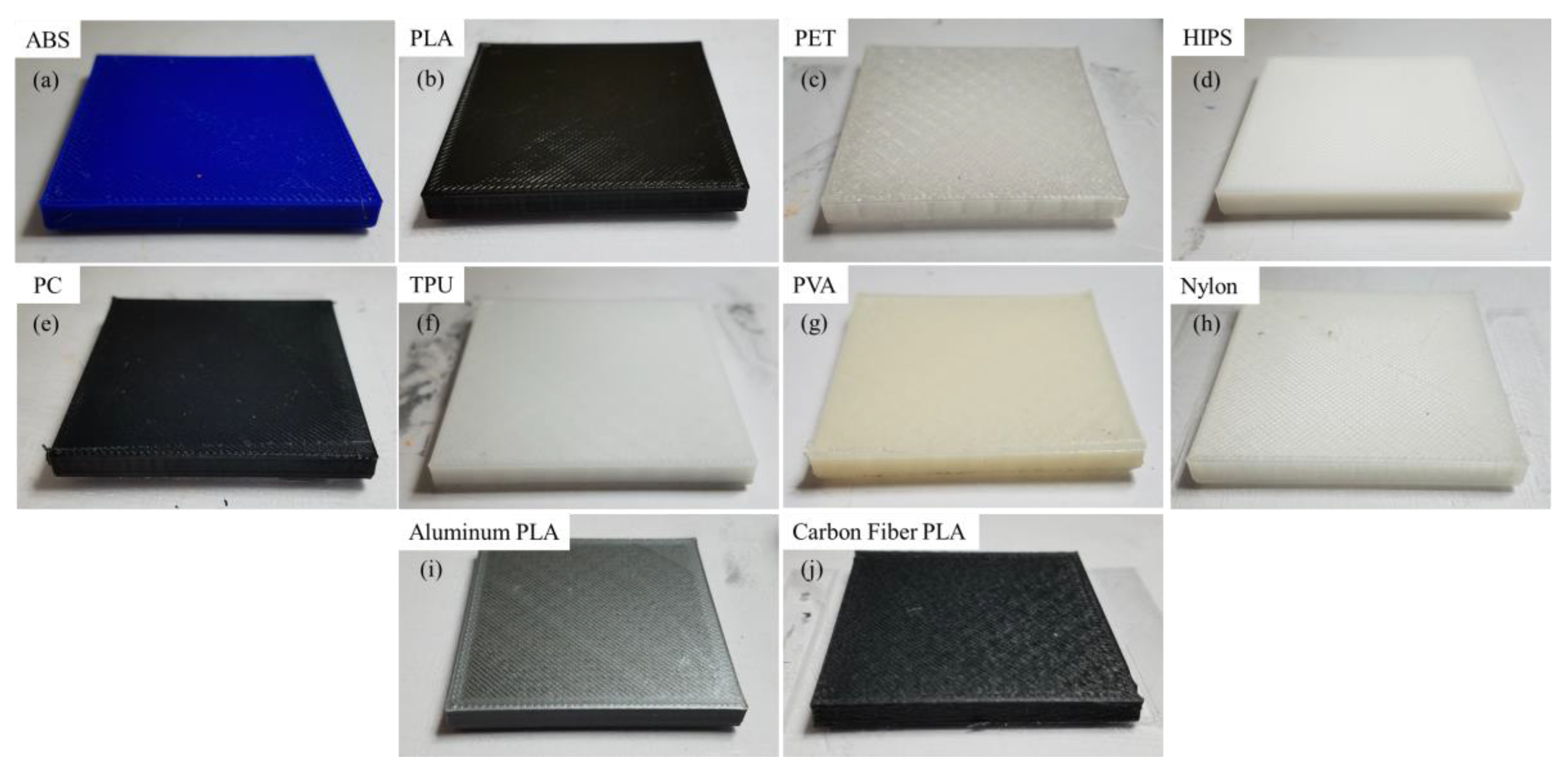


| Material | Formal Name/Composition | Material Source | |
|---|---|---|---|
| PC | Polycarbonate | eSUN | www.esun3d.net |
| ABS | Acrylonitrile butadiene styrene | Hatchbox | www.hatchbox3d.com |
| PLA | Polylactic acid | Hatchbox | www.hatchbox3d.com |
| PET | Polyethylene terephthalate | Gizmodorks | www.Gizmodorks.com |
| HIPS | High-impact polystyrene | Gizmodorks | www.Gizmodorks.com |
| Nylon | Synthetic polyamide | eSUN | www.esun3d.net |
| TPU | Thermoplastic polyurethane | ZIRO | www.ziro3d.com |
| PVA | Polyvinyl alcohol | Sainsmart | www.sainsmart.com |
| PLA + AL | PLA with 40% aluminum powder impregnation | Sainsmart | www.sainsmart.com |
| PLA + CF | PLA with 15% carbon fiber impregnation | Solutech | www.3dsolutech.com |
| Surface Roughness (μm) | Mean | SD |
|---|---|---|
| Aluminum | 8.19 | 2.96 |
| Aluminum with painter’s tape | 100.58 | 10.50 |
| Tempered glass | 1.62 | 1.32 |
| Tempered glass with CubeGlue | 46.31 | 11.01 |
| Polycarbonate | 24.96 | 3.60 |
| Polycarbonate with CubeGlue | 56.51 | 10.48 |
| Printed Material | (°C) | (°C) | (μm) | (μm) | (%) | (mm/s) |
|---|---|---|---|---|---|---|
| PC | 245 | 80 | 200 | 800 | 20 | 60 |
| ABS | 230 | 90 | 200 | 800 | 20 | 60 |
| PLA | 205 | 70 | 200 | 800 | 20 | 60 |
| PET | 245 | 80 | 200 | 800 | 20 | 60 |
| HIPS | 240 | 90 | 200 | 800 | 20 | 60 |
| Nylon | 240 | 70 | 200 | 800 | 20 | 60 |
| TPU | 220 | 70 | 200 | 800 | 20 | 20 |
| PVA | 205 | 70 | 200 | 800 | 20 | 60 |
| Aluminum PLA | 205 | 70 | 200 | 800 | 20 | 60 |
| Carbon Fiber PLA | 220 | 70 | 200 | 800 | 20 | 80 |
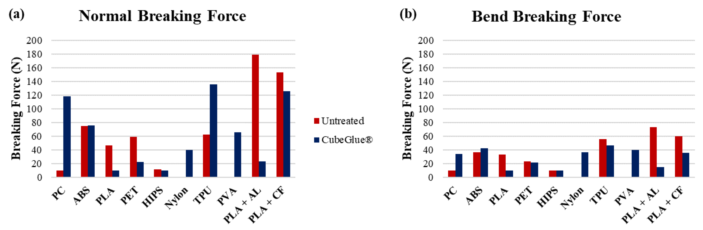
| Printed Material | Adhesion | Normal Breaking Force (N) | Bend Breaking Force (N) | Plate Surface Damage |
|---|---|---|---|---|
| PC | Fair | <10 | <10 | None observed |
| ABS | Good | 74.8 | 36.4 | None observed |
| PLA | Good | 46.5 | 33.3 | None observed |
| PET | Good | 58.7 | 23.5 | None observed |
| HIPS | Good | 11.8 | <10 | None observed |
| Nylon | None | Part Failed | Part Failed | None observed |
| TPU | Good | 62.4 | 55.8 | None observed |
| PVA | None | Part Failed | Part Failed | None observed |
| Aluminum PLA | Good | 179 | 73.5 | Etching (Mean = 27 μm) |
| Carbon Fiber PLA | Good | 153 | 59.8 | Etching (Mean = 86 μm) |
| Printed Material | Adhesion | Normal Breaking Force (N) | Bend Breaking Force (N) | Plate Surface Damage |
|---|---|---|---|---|
| PC | Good | 118 | 34.3 | None observed |
| ABS | Good | 75.6 | 42.6 | None observed |
| PLA | Good | <10 | <10 | None observed |
| PET | Good | 22.5 | 21.8 | None observed |
| HIPS | Good | <10 | <10 | None observed |
| Nylon | Good | 40.2 | 36.4 | None observed |
| TPU | Good | 136 | 46.9 | None observed |
| PVA | Good | 65.4 | 40.2 | None observed |
| Aluminum PLA | Good | 23.5 | 15.3 | None observed |
| Carbon Fiber PLA | Good | 126 | 36.2 | None observed |
| Material | Plate Configuration | Results |
|---|---|---|
| PC | Untreated tempered glass | Part detached and failed halfway through print |
| Tempered glass with CubeGlue® | Partial detachment, but part was able to complete | |
| Untreated aluminum | Complete detachment and failure on first layer | |
| Aluminum with painter’s tape | Successful print | |
| ABS | Untreated tempered glass | Partial detachment, but part was able to complete |
| Tempered glass with CubeGlue® | Successful print | |
| Untreated aluminum | Complete detachment and failure on first layer | |
| Aluminum with painter’s tape | Partial detachment, but part was able to complete | |
| PLA | Untreated tempered glass | Successful print |
| Tempered glass with CubeGlue® | Successful print | |
| Untreated aluminum | Successful print | |
| Aluminum with painter’s tape | Successful print | |
| PET | Untreated tempered glass | Successful print |
| Tempered glass with CubeGlue® | Successful print | |
| Untreated aluminum | Complete detachment and failure on first layer | |
| Aluminum with painter’s tape | Successful print | |
| HIPS | Untreated tempered glass | Successful print |
| Tempered glass with CubeGlue® | Successful print | |
| Untreated aluminum | Complete detachment and failure on first layer | |
| Aluminum with painter’s tape | Successful print | |
| Nylon | Untreated tempered glass | Partial detachment, but part was able to complete |
| Tempered glass with CubeGlue® | Successful print | |
| Untreated aluminum | Complete detachment and failure on first layer | |
| Aluminum with painter’s tape | Successful print | |
| TPU | Untreated tempered glass | Part detached and failed halfway through print |
| Tempered glass with CubeGlue® | Successful print | |
| Untreated aluminum | Complete detachment and failure on first layer | |
| Aluminum with painter’s tape | Successful print | |
| PVA | Untreated tempered glass | Successful print |
| Tempered glass with CubeGlue® | Successful print | |
| Untreated aluminum | Complete detachment and failure on first layer | |
| Aluminum with painter’s tape | Successful print | |
| PLA + AL | Untreated tempered glass | Successful print |
| Tempered glass with CubeGlue® | Successful print | |
| Untreated aluminum | Partial detachment, but part was able to complete | |
| Aluminum with painter’s tape | Successful print | |
| PLA + CF | Untreated tempered glass | Successful print |
| Tempered glass with CubeGlue® | Successful print | |
| Untreated aluminum | Part detached and failed halfway through print | |
| Aluminum with painter’s tape | Successful print |
© 2018 by the authors. Licensee MDPI, Basel, Switzerland. This article is an open access article distributed under the terms and conditions of the Creative Commons Attribution (CC BY) license (http://creativecommons.org/licenses/by/4.0/).
Share and Cite
Messimer, S.L.; Patterson, A.E.; Muna, N.; Deshpande, A.P.; Rocha Pereira, T. Characterization and Processing Behavior of Heated Aluminum-Polycarbonate Composite Build Plates for the FDM Additive Manufacturing Process. J. Manuf. Mater. Process. 2018, 2, 12. https://doi.org/10.3390/jmmp2010012
Messimer SL, Patterson AE, Muna N, Deshpande AP, Rocha Pereira T. Characterization and Processing Behavior of Heated Aluminum-Polycarbonate Composite Build Plates for the FDM Additive Manufacturing Process. Journal of Manufacturing and Materials Processing. 2018; 2(1):12. https://doi.org/10.3390/jmmp2010012
Chicago/Turabian StyleMessimer, Sherri L., Albert E. Patterson, Nasiha Muna, Akshay P. Deshpande, and Tais Rocha Pereira. 2018. "Characterization and Processing Behavior of Heated Aluminum-Polycarbonate Composite Build Plates for the FDM Additive Manufacturing Process" Journal of Manufacturing and Materials Processing 2, no. 1: 12. https://doi.org/10.3390/jmmp2010012