Article

Application of Finite Element Method to Analyze the Influences of Process Parameters on the Cut Surface in Fine Blanking Processes by Using Clearance-Dependent Critical Fracture Criteria

1
Graduate School of Science and Engineering, Saga University, 1 Honjo, Saga 840-8502, Japan
2
Department of Mechanical Engineering, Saga University, 1 Honjo, Saga 840-8502, Japan
3
Industry Technology Center of Saga, 114 Yaemizo, Nabeshima-cho, Saga 849-0932, Japan
*
Author to whom correspondence should be addressed.
J. Manuf. Mater. Process. 2018, 2(2), 26; https://doi.org/10.3390/jmmp2020026
Submission received: 29 March 2018 / Revised: 17 April 2018 / Accepted: 19 April 2018 / Published: 23 April 2018
(This article belongs to the Special Issue Precision Manufacturing)

Abstract

:
The correct choice of process parameters is important in predicting the cut surface and obtaining a fully-fine sheared surface in the fine blanking process. The researchers used the value of the critical fracture criterion obtained by long duration experiments to predict the conditions of cut surfaces in the fine blanking process. In this study, the clearance-dependent critical ductile fracture criteria obtained by the Cockcroft-Latham and Oyane criteria were used to reduce the time and cost of experiments to obtain the value of the critical fracture criterion. The Finite Element Method (FEM) was applied to fine blanking processes to study the influences of process parameters such as the initial compression, the punch and die corner radii and the shape and size of the V-ring indenter on the length of the sheared surface. The effects of stress triaxiality and punch diameters on the cut surface produced by the fine blanking process are also discussed. The verified process parameters and tool geometry for obtaining a fully-fine sheared SPCC surface are described. The results showed that the accurate and stable prediction of ductile fracture initiation can be achieved using the Oyane criterion.

1. Introduction

The fine blanking process is used to produce fine sheared surfaces in metal forming processes. It is used in the manufacturing of high-quality and precision components such as aircraft and automobile parts. The initial compression plays an important role, and the V-ring indenter, which provides compressive hydrostatic stress, is pressed into the blank before cutting in the fine blanking processes. The counter punch force holds the sheet to prevent bending of the sheet during blanking. The tool geometry characteristics of fine blanking, such as the size and shape of the V-ring indenter, the punch-die corner radii and the small clearance of less than 1% of the sheet thickness, are parameters that need to be chosen appropriately for an accurate fine blanking process.
Researchers have used various criteria, taking into account different influenced parameters, in the prediction of the nature of cut surfaces produced by the conventional punching and fine blanking processes. The predictive accuracies of phenomenological fracture criteria in the fine blanking process have been studied by Zhao et al. In that work, the Rice-Tracey criterion was modified by considering the effects of the volume and shape change of the voids for the accurate prediction of fracture initiation [1].
Hambli used a pressure-dependent damage model for fine blanking processes, and the results showed that the exponential damage evolution model was the best one [2]. The relationships between the punch-die clearance and the length of the sheared surface in the fine blanking process were investigated by Kwak et al. In that work, the Cockcroft-Latham criterion was used, and the influence of the punch-die clearance on the fracture zone, shear zone and die-roll were described [3]. A finite element method incorporating void damage was developed by Yu-min Li et al. to study the influences of process parameters on the fine blanking process [4].
Thipprakmas analyzed the V-ring indenter mechanism in the fine blanking process, and the effects of the V-ring on the compressive stress and material flow during the cutting phase were described [5]. Tanaka et al. used the Cockcroft-Latham, Oyane and Rice and Tracey criteria to study the shear droop on the punched surface in the fine blanking process and found that the differences between the shear droops obtained from FEM simulations and the experimental values could be reduced by implementing a remeshing function [6].
The forming quality of part shape in the fine blanking process with the Oyane fracture criterion was studied by Liu et al., and the relationships between the part shape and the die-roll height and crack surface height were described [7]. The predictive accuracies of the Ayada and Cockcroft-Latham criteria for micro-forming processes were studied by Meng et al. [8]. The V-ring was replaced with a trough, and the conditions of the cut surfaces were studied by Wang et al., with the results showing that a fully sheared surface was obtained with a trough on the die [9]. Mao et al. investigated the discontinuous dot indenter effect in the fine blanking process to reduce the difficulties in the manufacture of V-ring indenters. The Oyane fracture criterion was used, and a clean-cut surface part was obtained with the discontinuous dot indenter blank holder [10]. The Oyane criterion was used by Tang et al. to propose a new die design, showing that the size of the die-roll was reduced with the proposed die design [11].
The nesting strategy was used by Voigts et al. in the fine blanking process to investigate the height of die-roll [12]. Luo et al. used the Oyane fracture criterion and proposed a method for minimizing the length of die-roll in the fine blanking process. In that work, a method that was easier than negative clearance blanking and counter shearing cutting was proposed [13]. The Cockcroft-Latham, Ayada and Brozzo criteria were used by Yoshida et al. to decide the critical damage values, and the results indicated that the critical damage values varied with the initial ratio of thickness to width, and that the critical damage value was not a material unique constant [14].
In the above-mentioned research, the critical damage value was determined experimentally and that value was set to be constant for one material and was used in the fracture initiation analysis. Hence, experiments with long durations are required to obtain the critical damage value, and experimental costs are high. In order to reduce these conditions, the clearance-dependent critical ductile fracture criterion (C) determined by Cockcroft-Latham and the Oyane fracture criterion obtained from a previous publication [15] were used in this study. Hence, the costs and time required for the experiments to obtain the value of the critical ductile fracture criterion can be reduced or eliminated. The influence of the punch and die corner radii on the cut surface was studied, and the results showed that the sheared surface length is affected by the punch and die corner radii. The influences of initial compression, stress triaxiality and the V-ring on the cut surface are discussed. The process parameters and tool geometry for the production of a fully fine sheared surface of SPCC, the verification of optimized parameters and the effect of the punch diameter are described.

2. Ductile Fracture Criteria and Determination of Critical Fracture Criteria, (C)

2.1. Ductile Fracture Criteria

Three steps—initiation of voids, growth of existing voids, and hole coalescence—are involved in the ductile fracture process. The coupled and uncoupled models are used for predicting ductile fracture initiation in metal forming processes. The coupled models have material constants that are necessary to identify through experiments. In this study, empirical criteria or uncoupled criteria were used for the prediction of shear limit point or fracture initiation point.
Empirical criteria or uncoupled criteria are easy to implement in FEM code, and the critical values of these criteria can be determined by using known parameters such as stress and strain. The common uncoupled criteria chosen from the aforementioned research and literature, the Cockcroft-Latham and Oyane criteria, were used in this study. The Cockcroft-Latham criterion has no constant. The maximum principal stress over the plastic strain path was considered in that criterion [16]. There is only one material constant in the Oyane criterion, and it can be changed depending on the type of material [17].
0 ϵ ¯ f σ m a x σ e q d ϵ ¯ = C 1 ( C o c k c r o f t   a n d   L a t h a m )
0 ϵ ¯ f ( α + σ H σ e q ) d ϵ ¯ = C 2 ( O y a n e )
In the above criteria, σ m a x is the maximum principal stress, ϵ ¯ is the equivalent strain at fracture initiation, σ H is the hydrostatic pressure, σ e q is the equivalent von Mises stress, and α is the constant, the value of which depends on the material. In this study, an α value of 0.55 [15] was used.

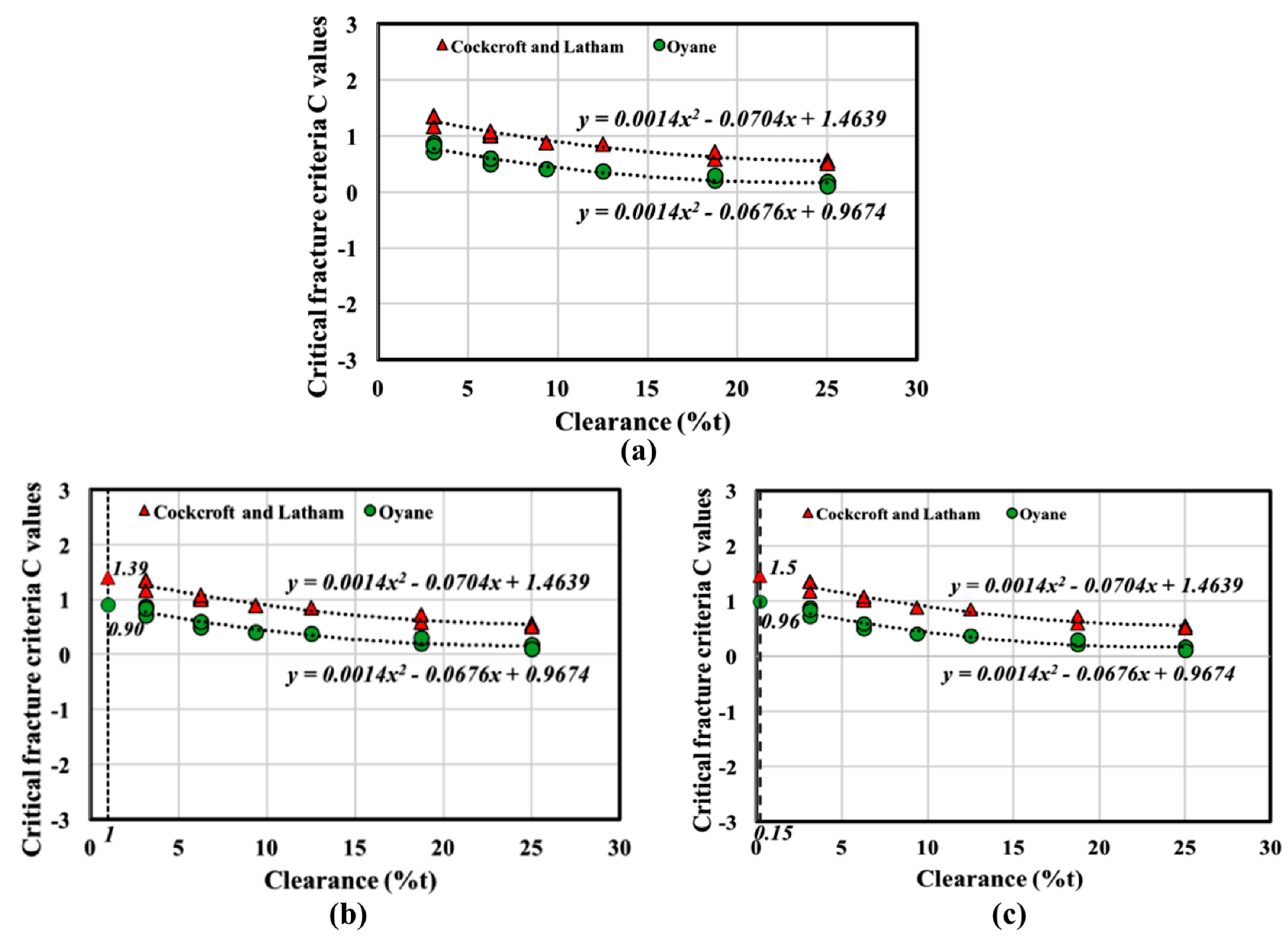
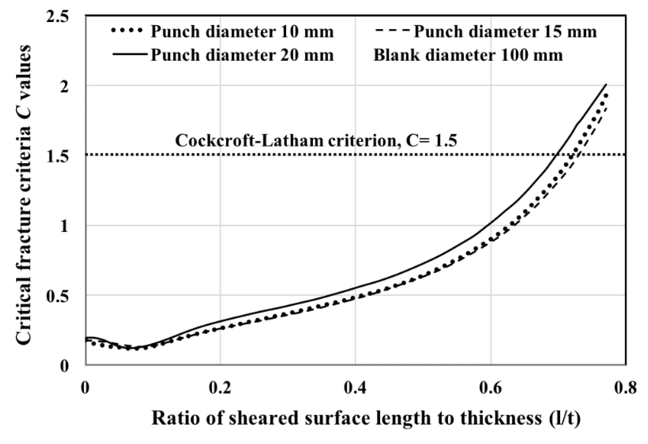
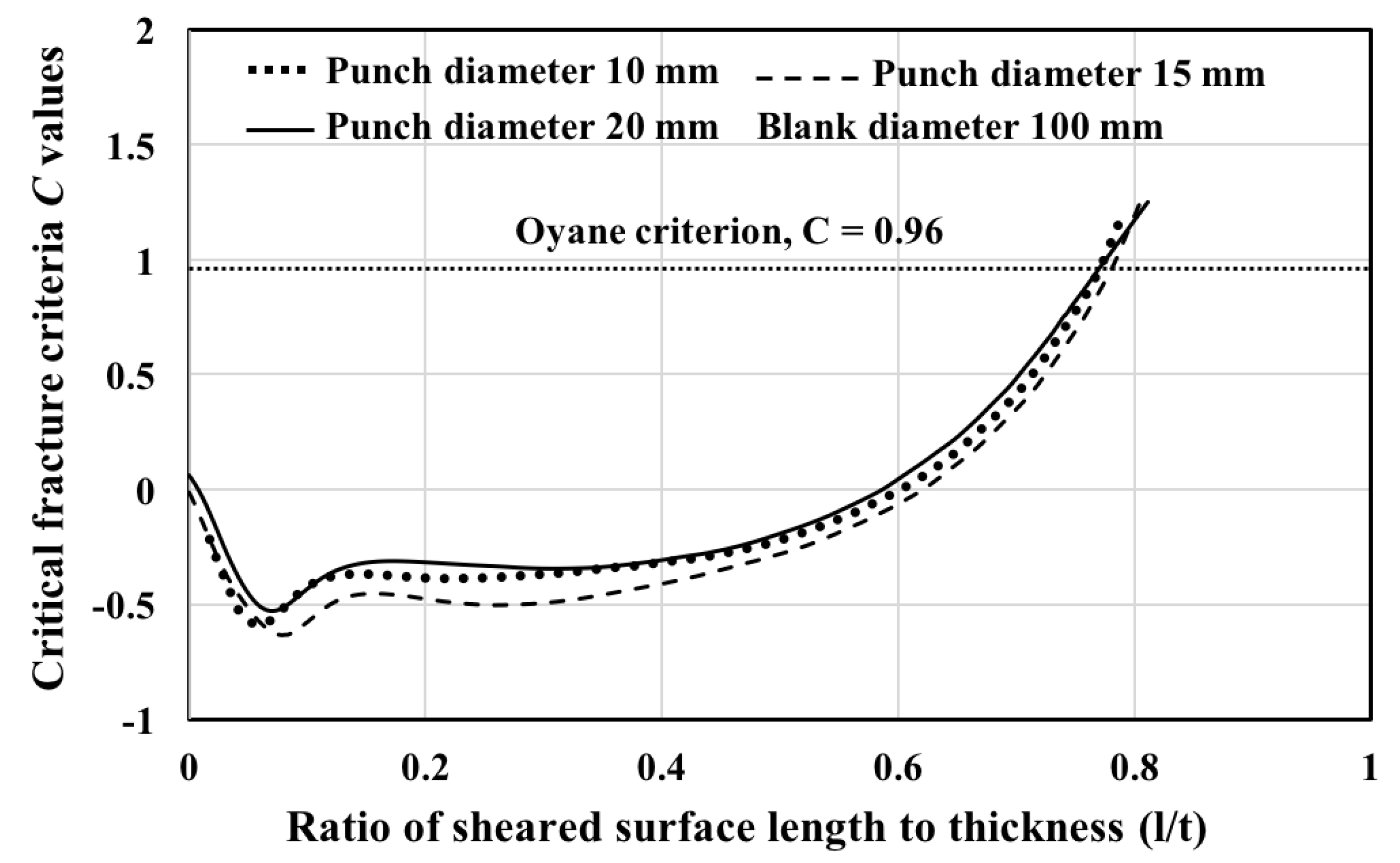
2.2. Determination of Critical Fracture Criteria, (C)

Some authors assume that the critical fracture criterion (C) is a material constant for one ductile fracture model, and that the value can be determined by experiments, such as tensile or compression tests. However, it was found in [15] that the value of the critical fracture criterion (C) varies with the clearance between the punch and the die. In that work, the values of the critical fracture criteria were determined by the combination of experiments and numerical analyses. The relationships between the ratios of sheared surface length to thickness and the clearances were obtained from punching experiments. The distributions of fracture criteria along the cutting length were obtained from the Finite Element Analysis (FEA) of the punching process. The ratios of sheared surface length to thickness obtained from the experiments and the cutting lengths obtained from the FEA were compared, and an accurate critical fracture criterion (C) was obtained through a best-fit of the experimental data. The results indicated that the critical value depends on the clearance. The relationships between the critical ductile fracture value (C) and clearance for SPCC at a maximum punch diameter of 25 mm are described in Figure 1a [15].
In order to reduce the time and costs associated with long-duration experiments for obtaining the value of the critical fracture criteria, the clearance-dependent critical fracture criteria obtained from Figure 1a were used to study the influences of process parameters in the fine blanking processes. The critical value of the ductile fracture criterion (C) can be obtained from Figure 1a for different clearances and various thicknesses of the blank with a maximum punch diameter of 25 mm without requiring experiments.
The small clearance of less than 1% of the sheet thickness is one of the important characteristics of the fine blanking processes. In this work, the critical ductile fracture criteria for the clearances of 1%t and 0.15%t were calculated from Figure 1a and used in predicting the nature of the cut surface. The critical fracture criteria values are shown in Figure 1b,c. The critical fracture criteria (C) values are 1.39 and 1.5 (Cockcroft and Latham), 0.9 and 0.96 (Oyane), assuming clearances of 1%t and 0.15%t.

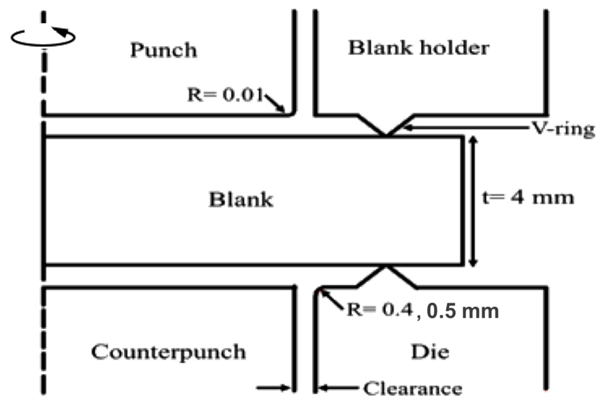
3. Finite-Element Analysis of Fine Blanking Processes

In order to analyze the influences of process parameters on the cut edge in the fine blanking process, a FEA model was created in the commercial FEM package MSC.Marc.Mentat and MSC.Marc. The axisymmetric model and geometrical data used in the simulations are shown in Figure 2. The blank diameter is 20 mm and the blank thickness is 4 mm. The V-ring indenter height is 0.7 mm and the diameter of punch used in the analysis is 10 mm.
The punch and die corner radii are 0.01 mm, 0.4 and 0.5 mm. Axisymmetric quadrangular four-node elements with remeshing function are used. The element length after remeshing is 0.01 mm. The blank is as assumed to be an elastic-plastic deformable body and the punch and the die are taken as rigid bodies. The effect of friction is more significant in metal forming processes such as the deep drawing process, and hence the friction between the material and the tool is not considered in this study. The quasi-static phenomenon is used, and the initial compression for hydrostatic compressive stress is initially set to 0.01 mm. The initial number of elements is 6250, and the initial element length is 0.08 mm.
The material SPCC was used in this study, and its properties were determined by the uniaxial tensile test. The Young’s modulus, E = 200 GPa, Poisson’s ratio, ν = 0.3 and yield stress, 154 MPa. The material properties used in the FEA are shown in Table 1.
The relations of multi-linear stress-strain were used in the FEA for approximation by the full Newton-Raphson iteration method. The ELEVAR user subroutine and plotv in MSC.Marc were used to create a program to study the distributions of fracture criteria and to decide critical fracture criteria by FEA.

4. Results and Discussion

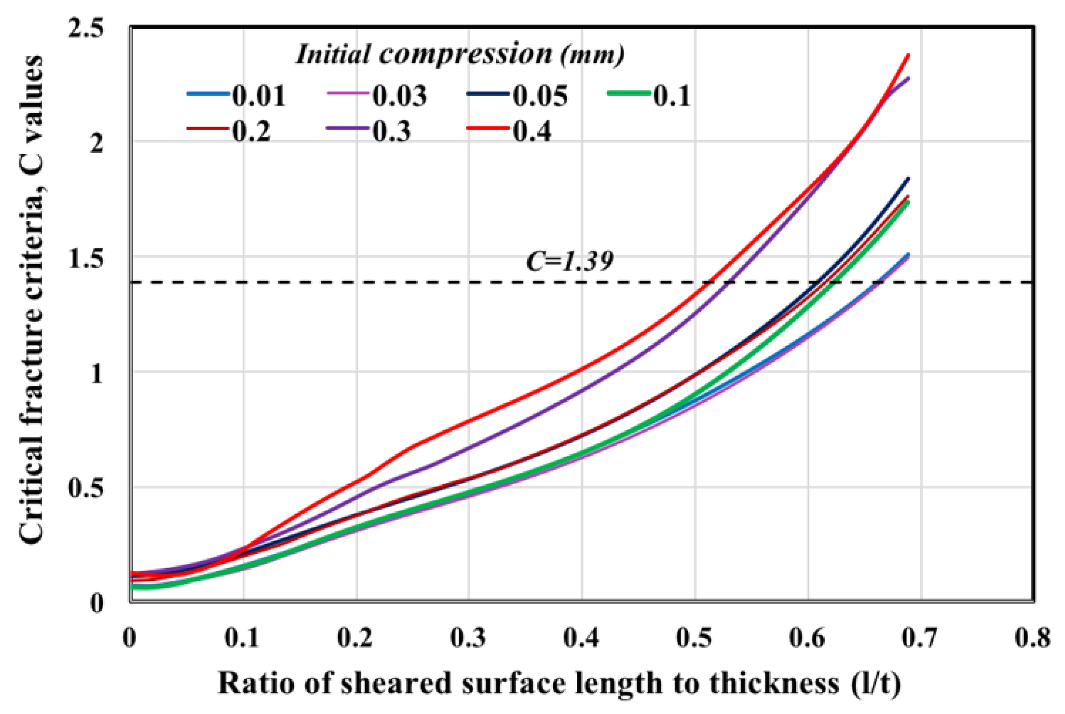
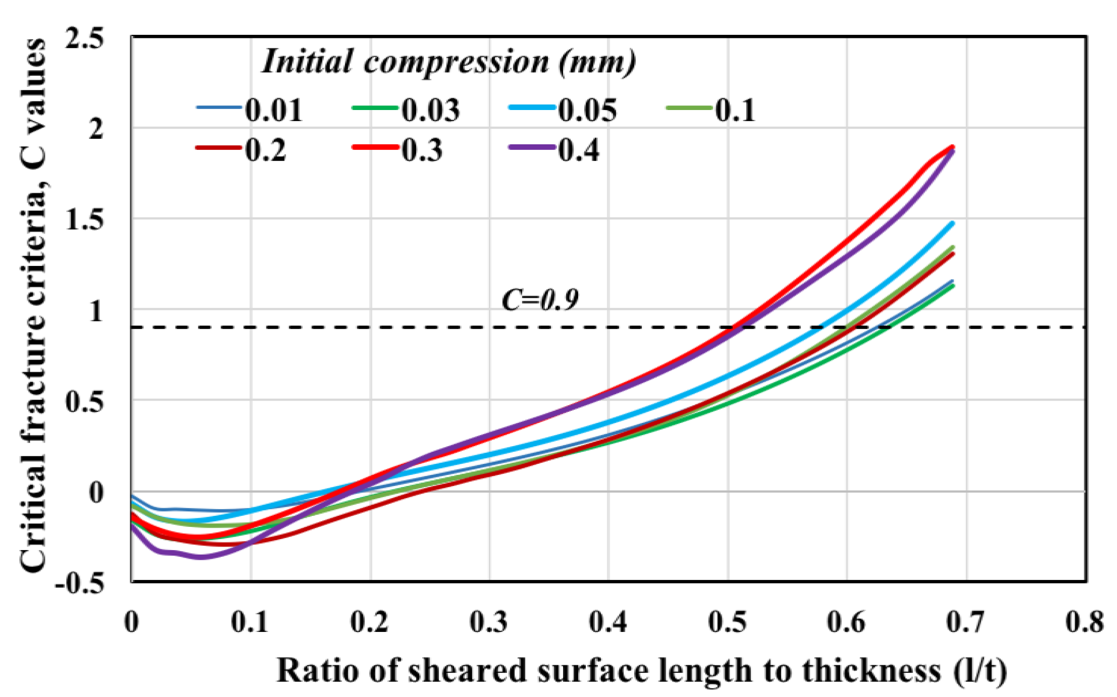
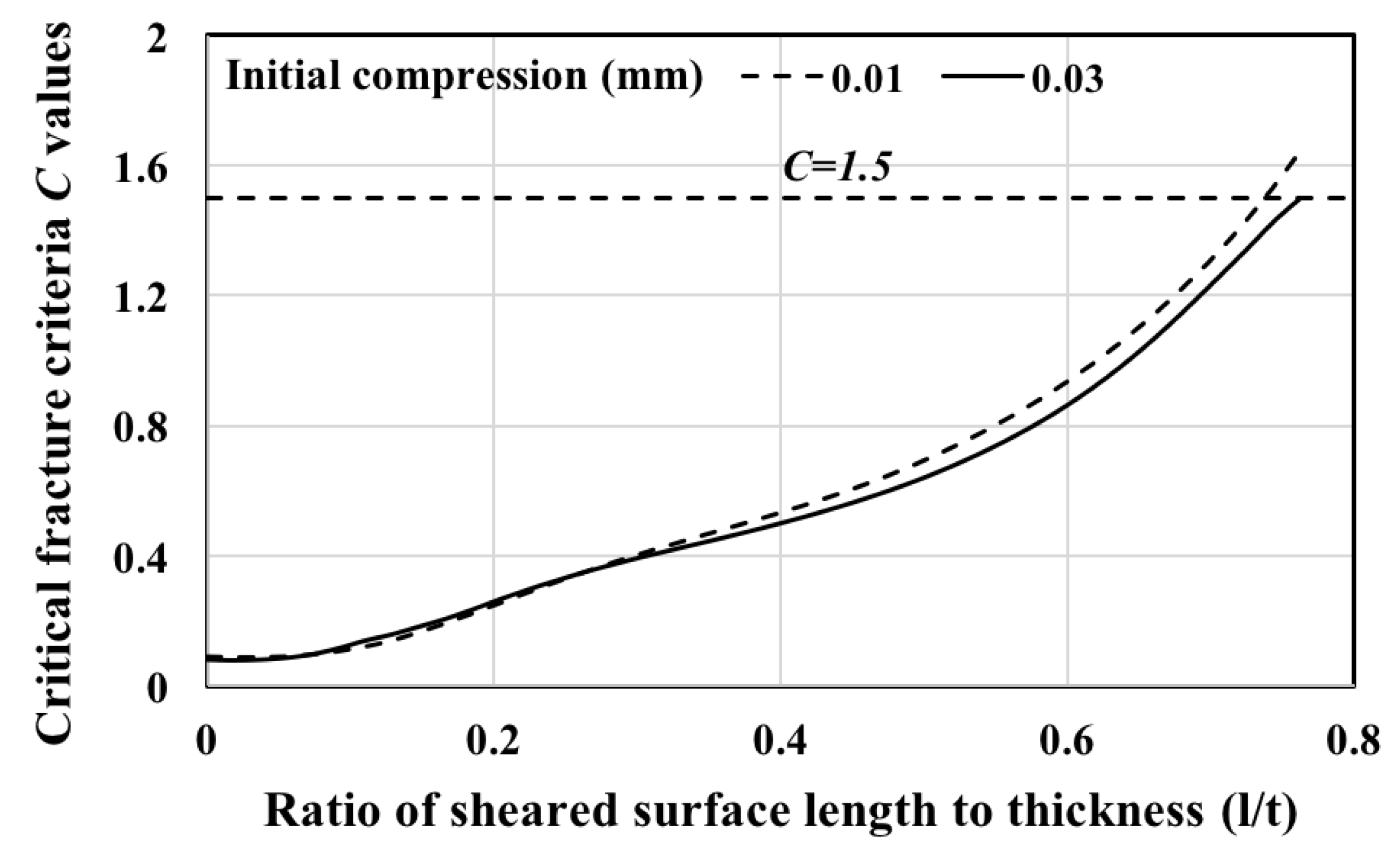
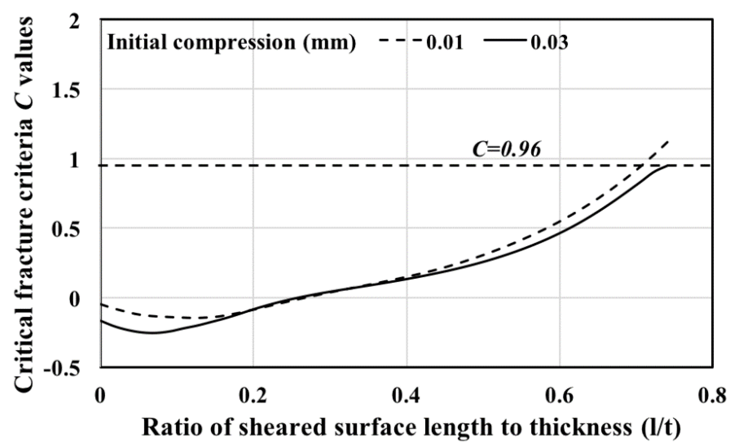
4.1. Effect of Initial Compression on the Sheared Surface Length

Swelling conditions were found between the counterpunch and the lower die when the tool geometry was not appropriately selected. This is due to the effect of initial compression and tool geometry, including lower die corner radius. The lower die corner radius was initially set to 0.4 mm, and the effects of initial compression on fracture initiation at a clearance of 1%t were studied. The lengths of the sheared surfaces with various initial compressions were predicted by using the threshold values of the Cockcroft-Latham and Oyane models. The results are depicted in Figure 3 and Figure 4.
Generally, the increase in the initial compression causes an increase in hydrostatic compressive stress. This postpones the fracture initiation point. From the other side, the increase in the initial compressive stress changes the stress state, and early fracture initiation can be found. This means that the increase in hydrostatic stress causes an increase in the range of stress triaxiality, and leads to fracture initiation. Hence, the right choice of initial compression is important. The figures show that larger sheared surfaces were obtained in the cases with initial compressions of 0.01 and 0.03 mm, and the minimum sheared surface lengths were obtained with initial compressions of 0.3 and 0.4 mm. These results indicate that there is a threshold value of initial compression for obtaining larger sheared surfaces under the same clearance value and the same critical fracture criterion (C) in the fine blanking process. Hence, the initial compression of 0.03 mm was initially chosen to analyze the effects of other process parameters on the fracture initiation point.

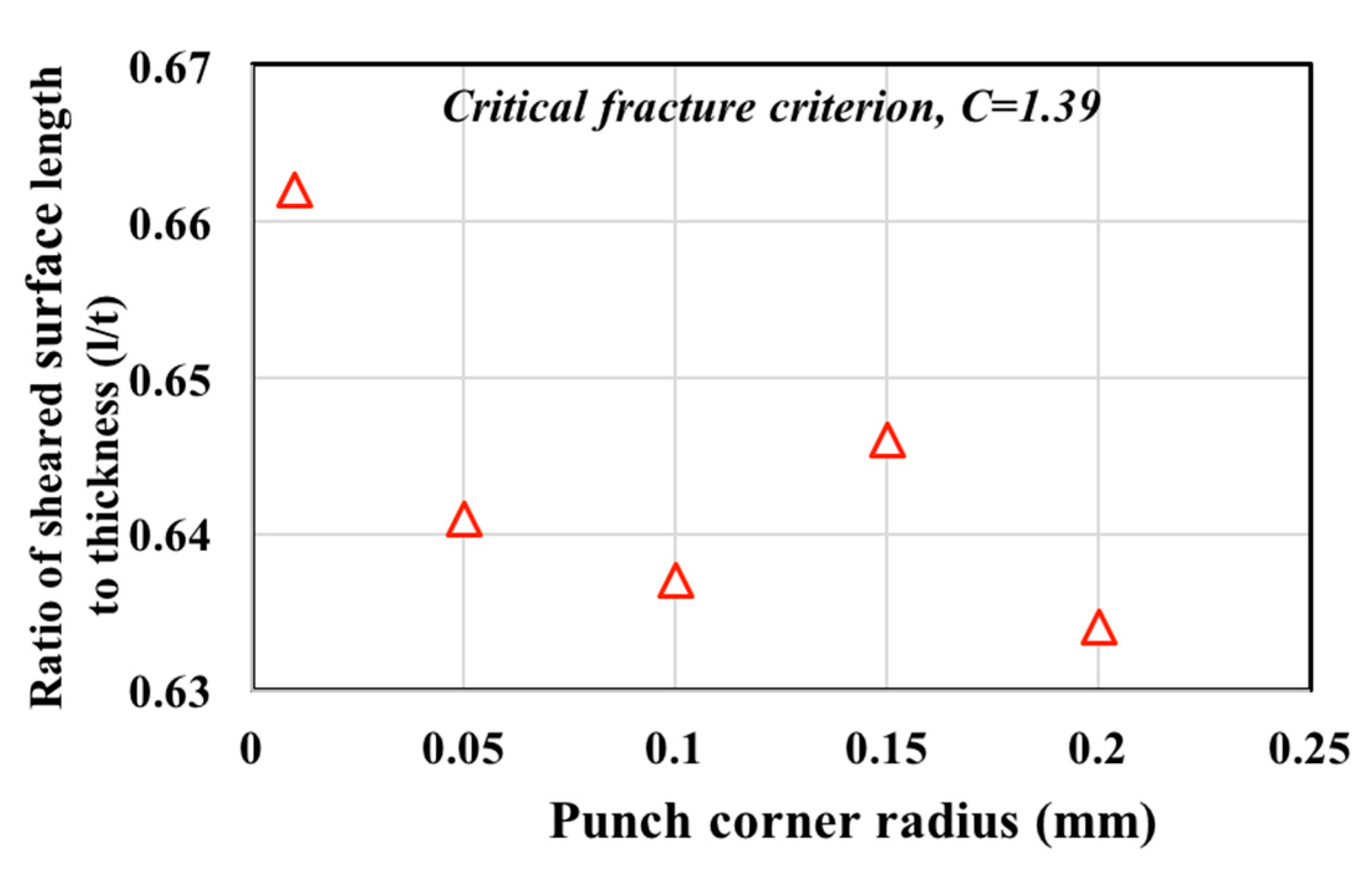
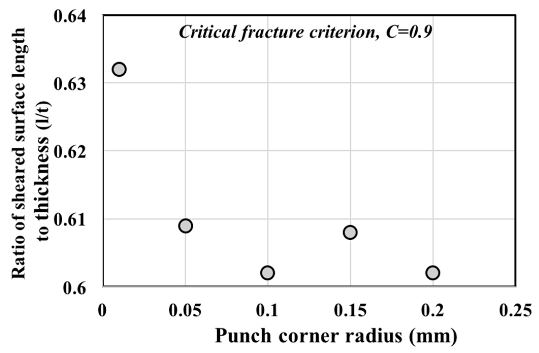
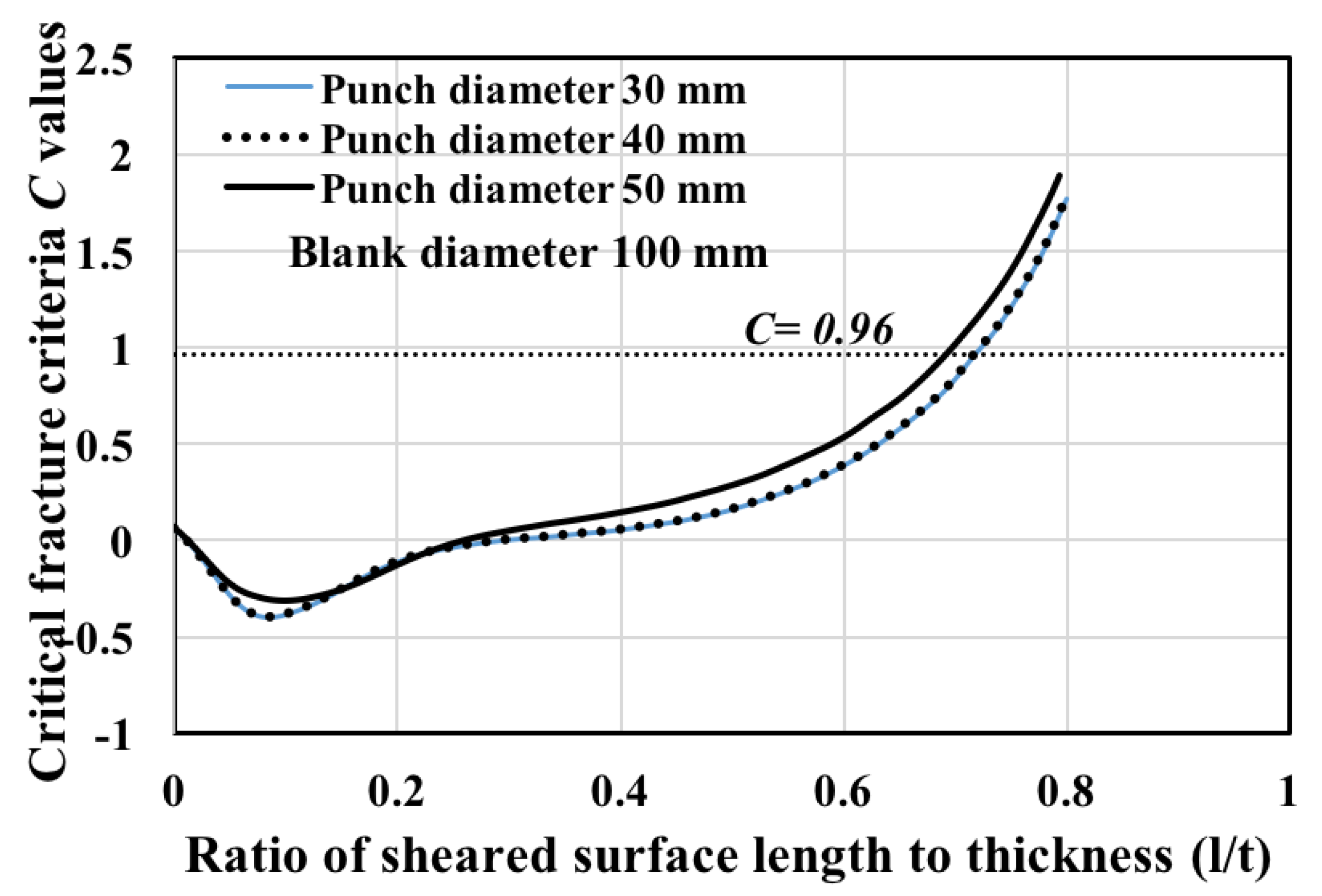
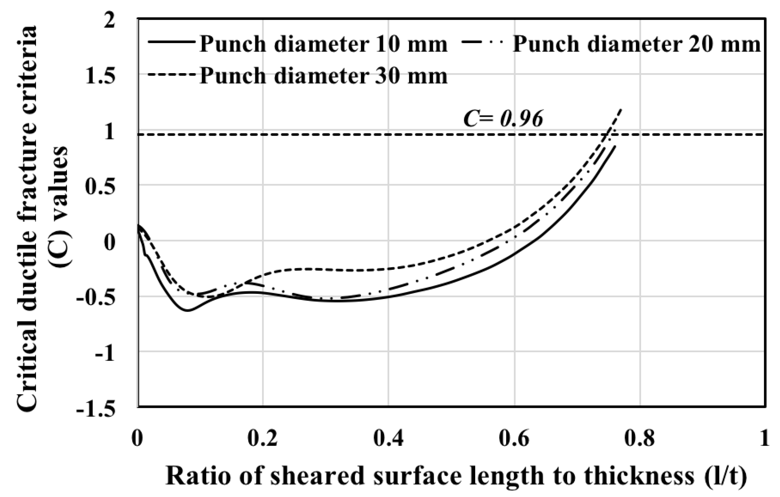
4.2. Effect of Punch Corner Radius on the Cut Surface

The tool geometry effect on the cut surface was also studied. The tool designs were not considered from an economical point of view or a wear point of view. The effect of punch corner radius on the length of sheared surface was studied at a clearance of 1%t and an initial compression of 0.03 mm. The relationships between punch corner radius and the length of the sheared surface can be seen in Figure 5 and Figure 6.
The condition of the cut surface also depends on the punch corner radius. Figure 5 and Figure 6 illustrate that a larger sheared surface was obtained with a smaller punch corner radius, and the largest length was obtained with a punch corner radius of 0.01 mm. The stress and strain values, and the length of the sheared surface decreased with an increase in the punch corner radius. The smaller punch corner radius causes higher compressive stress in the sheet and postpones fracture initiation at early punch displacements. From a wear point of view, researchers have found that the corner radius of the punch has a significant influence on the stress of the punch. The punch stress decreases with increasing punch corner radius, and the tool life also increases [18].

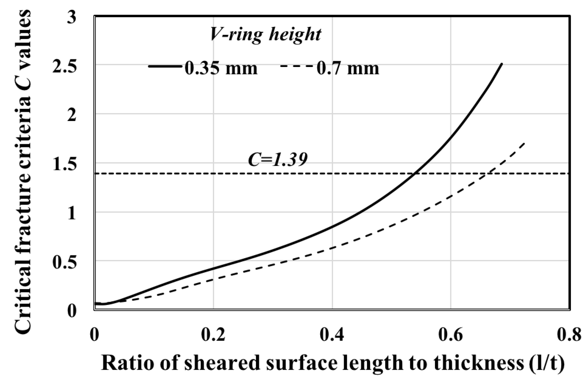
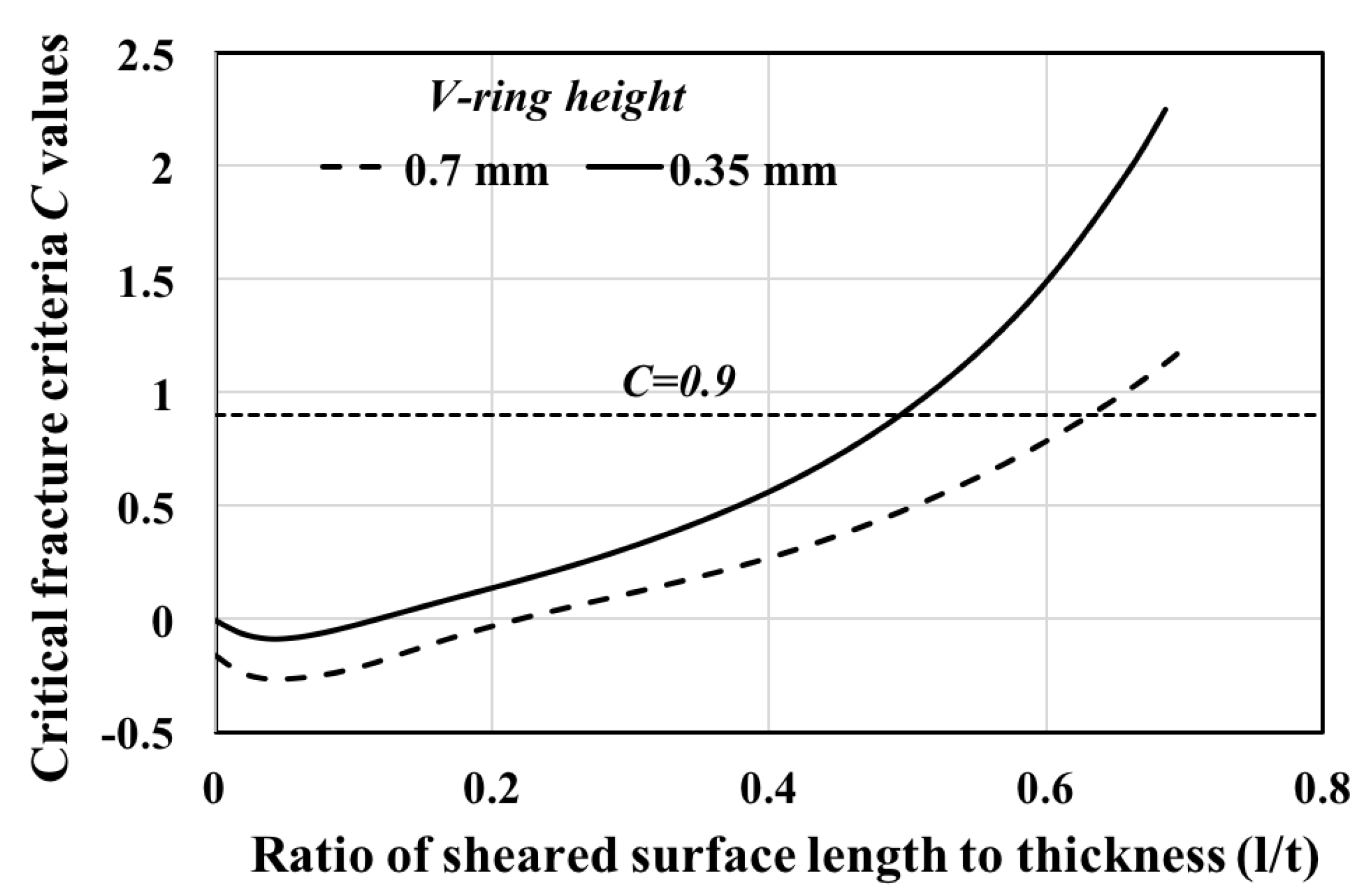
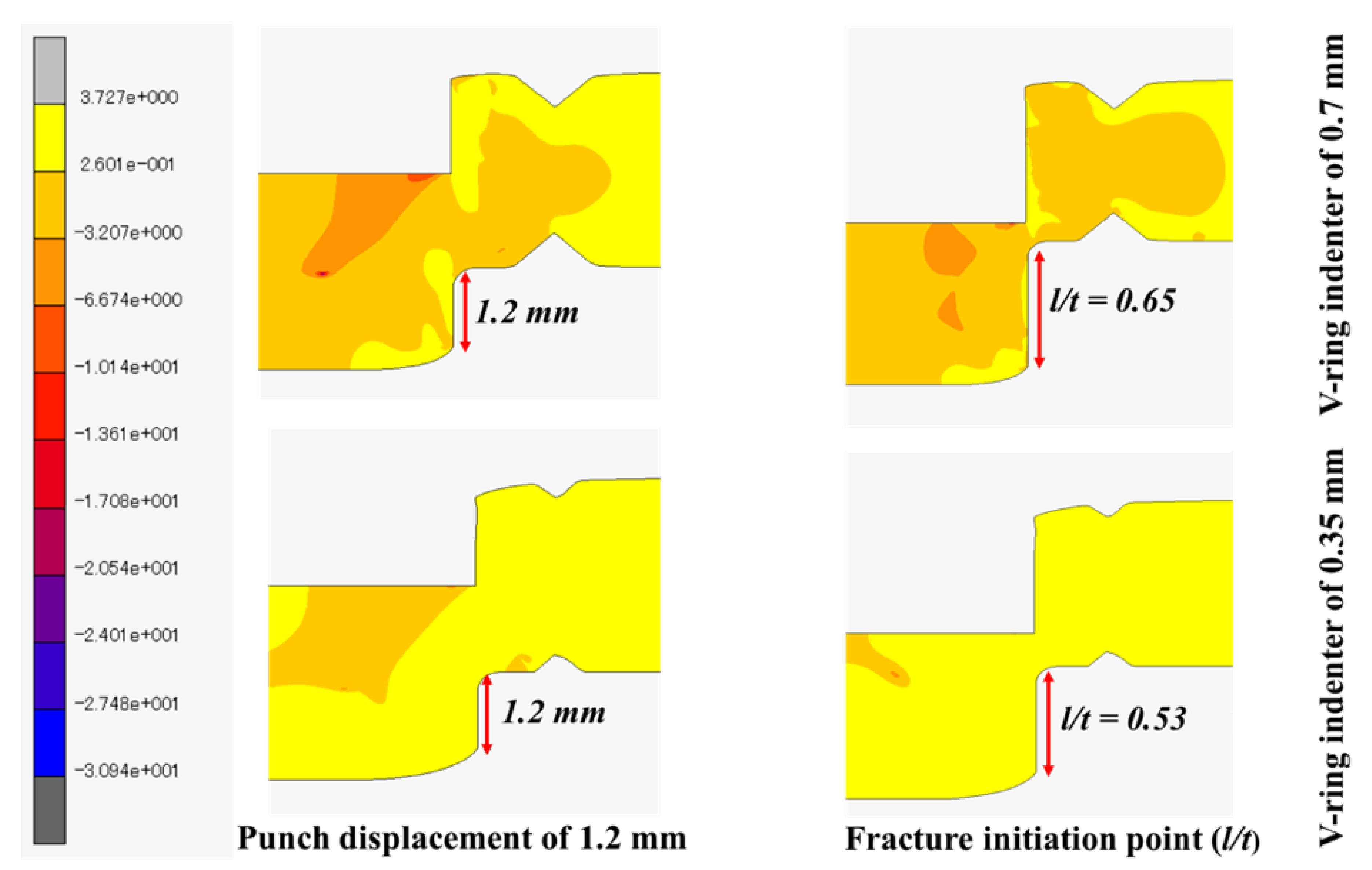
4.3. Effect of V-Ring Indenter on the Cut Surface

A V-ring indenter blank holder is used in fine blanking processes. The V-ring indenter is difficult to manufacture, and the effect of V-ring indenter parameters, such as the height, position and angle of the V-ring indenter, are important in the fine blanking process. The V-ring height should be chosen depending on the thickness of the blank to obtain a fully-fine sheared surface. In this study, the effect of the V-ring indenter height on the sheared surface length was studied using heights of 0.35 mm and 0.7 mm. The angle of the V-ring indenter for both cases was set to 90 and the distance from the punch was 1 mm.
The ratios of the length of sheared surface to thickness at V-ring indenter heights of 0.35 mm and 0.7 mm at a clearance of 1%t were investigated, and the results are shown in Figure 7 and Figure 8.
The figures illustrate that the right choice of V-ring indenter shape and size plays an important role in obtaining larger smooth surfaces in fine blanking processes. The ratio of sheared surface length to thickness was affected by the height of V-ring. The length of sheared surface with a V-ring indenter height of 0.7 mm was larger than the sheared surface length with a V-ring indenter height of 0.35 mm. This shows that higher V-ring indenter heights increase the compressive hydrostatic stress around the shear band, leading to high ductility and postponing early fracture initiation [19]. These results indicate that a V-ring height of 0.7 mm is more reliable for a sheet thickness of 4 mm.

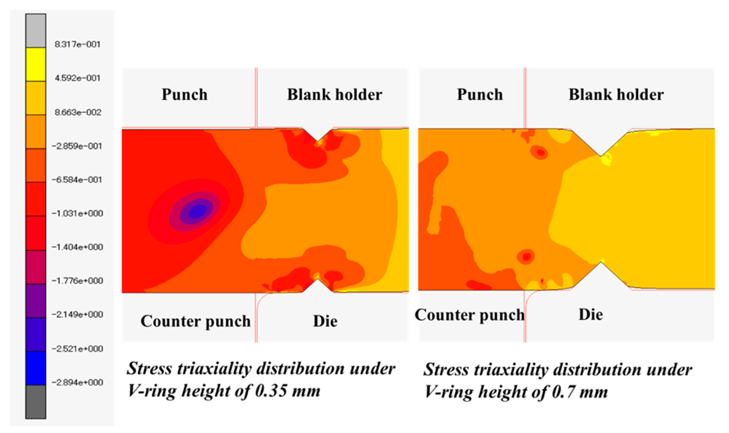
4.4. Effect of Stress Triaxiality

Complicated loading conditions are involved in the blanking process: tension, compression and shear. The range of variation of stress triaxiality (from negative values to positive values) is high during the blanking process. At negative triaxiality, the shear mode controls the process of fracturing. At high stress triaxiality, it is controlled by the growth of voids, and void growth together in combination with shear mode controls it at low values. Hence, the fracture lines are curved in the space of stress triaxiality [20].
The effect of stress triaxiality on the length of clean cut surfaces in fine blanking was also studied. The distribution of stress triaxiality under the V-ring indenter heights 0.35 and 0.7 mm can be seen in Figure 9.
High stress triaxiality was developed around the V-ring indenter. The highest stress triaxiality developed at the V-ring height of 0.7 mm. This decreased toward the inside of the blank and in the clearance zone (shearing zone). The compressive stress was increased by the V-ring indenter in the blank before cutting, which caused the rotation of material flow and an increase in hydrostatic compressive stress [5]. Hence, the sheared surface length was also affected by the V-ring indenter, which increases the hydrostatic stress before the cutting phase. The stress triaxiality variations during the punching process and at the fracture initiation point or shear limit point (l/t) are depicted in Figure 10.
The distributions of stress during the process of blanking at different V-ring indenter heights under the same clearance of 1%t were studied. The results from Figure 10 show the variations of stress triaxiality at a punch displacement of 1.2 mm and at the fracture initiation point (l/t) with different V-ring indenters. For the V-ring indenter height of 0.7 mm, at the stage of punch displacement, 1.2 mm, the highest stress triaxiality developed around the V-ring, and low stress triaxiality (negative value) was found in the clearance zone, at the middle of the blank. This prevents the formation of early fracture initiation. When the punch reaches the fracture initiation point (l/t), high stress triaxiality was acting along the cutting surface. The negative stress triaxiality in the middle decreased with the decrease in thickness. The triaxiality around the V-ring decreased, and high stress triaxiality developed in the clearance zone, leading to fracturing. For the V-ring indenter height of 0.35 mm, the distribution of stress triaxiality was significantly different from the V-ring indenter height of 0.7 mm. High stress triaxiality developed at the punch movement of 1.2 mm, and high stress triaxiality appeared in the whole blank at the fracture initiation or shear limit point. Earlier fracture initiation occurred due to the high stress triaxiality, and hence the sheared surface length at a V-ring height of 0.35 mm is smaller.

4.5. Selection of Optimized Parameters for Fine Blanking Process

The process parameters that give the largest sheared surface were selected based on the results obtained from the case of a clearance of 1%t and were used to predict the conditions of the cut surfaces under a clearance of 0.15%t. A V-ring height of 0.7 mm, initial compressions of 0.01 and 0.03 mm (from which larger sheared surfaces were obtained), and a punch corner radius of 0.01 mm were selected. The length of the sheared surface to thickness ratios with the selected parameter values were predicted at a clearance of 0.15%t by using the Cockcroft-Latham and Oyane critical criteria of 1.5 and 0.96. The result with the Cockcroft-Latham criterion is shown in Figure 11, and the result with the Oyane criterion is shown in Figure 12.
The distribution of damage values along the cutting length was above the critical fracture criteria (C) value for the initial compression of 0.01 mm. However, the damage distribution was below the threshold values of 1.5 (Cockcroft-Latham) and 0.96 (Oyane) for the initial compression of 0.03 mm, which means that the cut surface was fully sheared. The figures show that the fully sheared surface can be obtained using the optimized parameters with an initial compression of 0.03 mm, a punch corner radius of 0.01 mm, and a V-ring indenter height of 0.7 mm at a clearance of 0.15%t. These results indicate the importance of choosing appropriate process parameters for obtaining a fully sheared surface.

4.6. Verification of the Optimized Parameters

The parameters that give a fully sheared surface of SPCC in the fine blanking process were selected by using a punch diameter of 10 mm and a blank diameter of 20 mm. The predictions of the behavior of the cut surfaces were performed using the same clearance of 0.15%t by using a larger blank diameter (100 mm) and punch diameters (10, 15, 20, 30, 40 and 50 mm) to verify whether the optimized parameters and clearance-dependent ductile fracture criteria can be used for other conditions, such as larger blank diameters and larger punch diameters. The initial element length of 0.08 mm and the element length after remeshing, 0.01 mm, are the same as the former case of a blank diameter of 20 mm; the total number of elements is 31,250. The predicted cut surfaces for the blank diameter of 100 mm and the punch diameters of 10, 15 and 20 mm under the clearance of 0.15%t using the optimized parameters are shown in Figure 13 and Figure 14.
The figures show the conditions of the cut surfaces predicted by the Cockcroft-Latham and Oyane criteria. The results obtained from both criteria indicate that the predicted cut surfaces are not fully sheared for all punch diameters or for the blank diameter of 100 mm at the same clearance. The predicted cut surfaces using punch diameters of 30, 40 and 50 mm at the clearance of 0.15%t are shown in Figure 15 and Figure 16.
Figure 15 and Figure 16 show that the cut surfaces predicted by the Cockcroft-Latham and Oyane critical criteria (C) values are not fully sheared. The damage distribution along the cutting plane is larger than the threshold value. The die corner radius used in the previous predictions was 0.4 mm. Hence, the die corner radius was changed to 0.5 mm to obtain optimized parameters in the fine blanking process. The predicted cut surface lengths are shown in Figure 17 and Figure 18.
Figure 17 and Figure 18 show that the largest sheared surface can be obtained with a die corner radius of 0.5 mm for the various diameters at the same clearance of 0.15%t. Figure 17 shows the cut surfaces predicted with the Cockcroft-Latham criterion. The distribution of the Cockcroft-Latham fracture criterion is above the critical value of 1.5, meaning that the predicted cut surfaces are not fully sheared. Figure 18 shows the cut surfaces predicted with the Oyane criterion. The distribution of the Oyane fracture criterion along the cutting length is below the threshold value for the punch diameters of 10 and 20 mm. However, it is above the threshold value for the punch diameter of 30 mm. The predicted cut surfaces with a punch diameter of 30 mm are not fully sheared surfaces for the die corner radii of 0.4 mm and 0.5 mm, but the sheared surface length obtained with 0.5 mm is larger than the sheared surface length obtained with 0.4 mm.
These results verify that a fully sheared surface of SPCC can be obtained by using the following optimized parameters: initial compression of 0.03 mm, punch corner radius of 0.01 mm, die corner radius of 0.5 mm, and V-ring height of 0.7 mm. The figures also indicate that the clearance-dependent critical ductile fracture criteria obtained from [15] can be used to predict fracture initiation in the conventional punching and fine blanking processes up to a maximum punch diameter of 25 mm.

5. Conclusions

FEA was performed to observe the nature of cut surfaces of SPCC in the fine blanking process. The clearance-dependent critical ductile fracture criteria (C) determined by the Cockcroft-Latham and Oyane fracture criteria, described in a previous publication [15], were used. Based on the results, the conclusions are as follows.
In the fine blanking process, the quality of the product is affected by the punch-die clearance, the punch and die corner radii, the initial compression and the V-ring indenter. The correct choice of the process parameters plays an important role in predicting the conditions of cut surfaces in the fine blanking processes. The increase in the punch corner radius decreases the sheared surface length of the blank. The increase in the initial compression decreases the length of the sheared surface and the correct choice of the initial compression is crucial for compressive hydrostatic stress, which postpones the fracture initiation point.
The length of sheared surface obtained by the fine blanking process is also significantly affected by the V-ring. The results indicate that the sheared surface length obtained at a V-ring indenter height of 0.7 mm is larger than that at 0.35 mm. The V-ring height of 0.7 mm is appropriate for a blank thickness of 4 mm. The effect of stress triaxiality on the length of sheared surface was also studied, showing that the compressive stress was increased by the V-ring in the blank before cutting, causing material flow rotation, which affects the sheared surface length.
It was found that the fully sheared surface could be obtained by using the following optimized parameters: initial compression of 0.03 mm, punch corner radius of 0.01 mm, die corner radius of 0.5 mm and V-ring height of 0.7 mm
The results also indicate that cut surfaces obtained using the Oyane criterion with the chosen process parameters are fully sheared. It was also found that the accurate and stable prediction of ductile fracture initiation can be obtained using stress triaxiality and the equivalent plastic strain-based criterion, Oyane. The clearance-dependent critical damage value of the fracture criteria obtained from the previous publication [15] can be used in the prediction of the fracture initiation point of SPCC in the conventional punching process and the fine blanking process with a maximum punch diameter of up to 25 mm. Hence, the time required for experiments and the costs of experiments can be minimized by using these clearance-dependent critical ductile fracture criteria. Based on these results, it was also found that the influence of punch diameter on the length of sheared surface should also be considered in the prediction of fracture initiation in the blanking processes.

Acknowledgments

This research was funded by the Amada Foundation (AF-2011020), and the authors would like to thank the foundation for their funding support.

Author Contributions

Seiya Hagihara, Phyo Wai Myint and Toru Tanaka conceived and designed the analysis procedure. Seiya Hagihara, Phyo Wai Myint, Shinya Taketomi and Yuichi Tadano analyzed the data and wrote the paper.

Conflicts of Interest

The authors declare no conflict of interest.

References

  1. Zhao, Z.; Zhuang, X.; Xie, X. An improved ductile fracture criterion for fine blanking process. J. Shanghai Jiaotong Univ. 2008, 13, 702–706. [Google Scholar] [CrossRef]
  2. Hambli, R. Finite element simulation of fine blanking processes using a pressure dependent damage model. J. Mater. Process. Tech. 2001, 116, 252–264. [Google Scholar] [CrossRef]
  3. Kwak, T.S.; Kim, Y.J.; Bae, W.B. Finite element analysis on the effect of die clearance on shear planes in fine blanking. J. Mater. Process. Tech. 2002, 130–131, 462–468. [Google Scholar] [CrossRef]
  4. Li, Y.; Peng, Y. Fine-blanking process simulation by rigid viscous-plastic FEM coupled with void damage. J. Finite Elem. Anal. Des. 2003, 39, 457–472. [Google Scholar] [CrossRef]
  5. Thipprakmas, S. Finite element analysis of V-ring indenter mechanism in fine blanking process. J. Mater. Des. 2008. [Google Scholar] [CrossRef]
  6. Tanaka, T.; Hagihara, S.; Tadano, Y.; Yoshimura, S.; Inada, T.; Mori, T.; Fuchiwaki, K. Analysis of shear droop on cut surface of high-strength steel in fine blanking process. Mater. Trans. JSTP 2011, 52, 447–451. [Google Scholar] [CrossRef]
  7. Liu, Y.; Hua, L.; Mao, H.; Feng, W. Finite element simulation of effect of part shape on forming quality in fine blanking process. Procedia Eng. 2014, 81, 1108–1113. [Google Scholar] [CrossRef]
  8. Meng, B.; Fu, M.W.; Fu, C.M.; Chen, K.S. Ductile fracture and deformation behavior in progressive micro-forming. J. Mater. Des. 2015, 83, 14–25. [Google Scholar]
  9. Wang, J.P. A novel fine blanking approach. Int. J. Adv. Manuf. Technol. 2015, 78, 1015–1019. [Google Scholar] [CrossRef]
  10. Mao, H.; Zhou, F.; Liu, Y.; Hua, L. Numerical and experimental investigation of the discontinuous dot indenter in the fine blanking process. J. Manuf. Process. 2016, 24, 90–99. [Google Scholar] [CrossRef]
  11. Tang, B.; Liu, Y.; Mao, H. Investigation of a novel modified die design for fine-blanking process to reduce the die-roll size. Proc. Eng. 2017, 20, 1546–1551. [Google Scholar] [CrossRef]
  12. Voigt, H.; Trauth, D.; Feuerhack, A.; Mattfeld, P.; Klocke, F. Dependencies of the die-roll height during fine blanking of case hardening steel 16MnCr5 V-ring using a nesting strategy. Int. J. Adv. Manuf. Technol. 2018, 95, 3083–3091. [Google Scholar] [CrossRef]
  13. Luo, C.; Chen, Z.; Zhou, K.; Yang, X.; Zhang, X. A novel method to significantly decrease the die roll during fine blanking process with verification by simulation and experiments. J. Mater. Process. Tech. 2017, 250, 254–260. [Google Scholar] [CrossRef]
  14. Yoshida, Y.; Ishikawa, T. Determination of ductile damage parameters by notched plate tensile test using image analysis. J. Mater. Res. Innov. 2011, 15, s422–s425. [Google Scholar] [CrossRef]
  15. Phyo, W.M.; Hagihara, S.; Tanaka, T.; Taketomi, S.; Tadano, Y. Determination of the values of critical ductile fracture criteria to predict fracture initiation in punching processes. J. Manuf. Mater. Process. 2017, 1, 12. [Google Scholar] [CrossRef]
  16. Cockcroft, M.G.; Latham, D.J. Ductility and workability of metals. J. Inst. Metals 1968, 96, 33–39. [Google Scholar]
  17. Oyane, M.; Sato, T.; Okimoto, K.; Shima, S. Criteria for ductile fracture and their applications. J. Mech. Work. Tech. 1980, 4, 65–81. [Google Scholar] [CrossRef]
  18. Pacas, I.; Hernandez, R.; Casellas, D.; Valls, I. Strategies to increase the tool performance in punching operations of UHSS. In Proceedings of the 50th Anniversary Conference (IDDRG), Graz, Austria, 31 May–2 June 2010; pp. 325–334. [Google Scholar]
  19. Kwak, T.S.; Kim, Y.J.; Seo, M.K.; Bae, W.B. The effective of V-ring indenter on the sheared surface in the fine blanking process of pawl. J. Mater. Process. Tech. 2003, 143–144, 656–661. [Google Scholar] [CrossRef]
  20. Bao, Y.; Wierzbicki, T. On fracture locus in the equivalent strain and stress triaxiality space. Int. J. Mach. Sci. 2004, 46, 81–98. [Google Scholar] [CrossRef]
Figure 1. (a) The variation of the critical fracture criteria (C) with clearance, the relationship between critical fracture criterion (C) value and the clearance (b) at a clearance of 1%t and (c) at a clearance of 0.15%t, obtained by the polynomial equation in (a).
Jmmp 02 00026 g001
Figure 2. Axisymmetric model of the blank, blank holder with V-ring, punch, counter punch and punch corner radius (R = 0.01), die corner radii (R = 0.4, 0.5 mm) and blank thickness (t = 4 mm) used in the simulation of the fine blanking process.
Jmmp 02 00026 g002
Figure 3. The sheared surface length-to-thickness ratio predicted by the Cockcroft-Latham fracture criterion at a clearance of 1%t with various of initial compressions (mm).
Jmmp 02 00026 g003
Figure 4. The sheared surface length-to-thickness ratio predicted by the Oyane fracture criterion at a clearance of 1%t with various initial compressions (mm).
Jmmp 02 00026 g004
Figure 5. The relationships between the punch corner radius and the ratio of the sheared surface length to thickness at a clearance of 1%t (Cockcroft-Latham).
Jmmp 02 00026 g005
Figure 6. The relationships between the punch corner radius and the ratio of sheared surface length to thickness at a clearance of 1%t (Oyane).
Jmmp 02 00026 g006
Figure 7. The ratios of the length of sheared surface to thickness with reference to the heights of the V-ring indenter, 0.3 and 0.7 mm, with the Cockcroft-Latham criterion at a clearance of 1%t.
Jmmp 02 00026 g007
Figure 8. The ratios of the length of sheared surface to thickness with reference to the heights of the V-ring indenter, 0.3 and 0.7 mm, with the Oyane criterion at a clearance of 1%t.
Jmmp 02 00026 g008
Figure 9. The stress triaxiality distribution after V-rings (0.35 mm and 0.7 mm) were totally immersed in the blank at a clearance of 1%t.
Jmmp 02 00026 g009
Figure 10. The distributions of stress triaxiality during punch displacement (1.2 mm) and at the initiation of fracture (l/t) at V-ring indenter heights of 0.35 and 0.7 mm at a clearance of 1%t.
Jmmp 02 00026 g010
Figure 11. The ratios of the length of sheared surface to thickness predicted by using the selected parameters at a clearance of 0.15%t and a punch diameter of 10 mm for initial compressions of 0.01 mm and 0.03 mm (Cockcroft and Latham).
Jmmp 02 00026 g011
Figure 12. The ratios of the length sheared surface to thickness predicted by using the selected parameters at a clearance of 0.15%t and a punch diameter of 10 mm for initial compressions of 0.01 mm and 0.03 mm (Oyane).
Jmmp 02 00026 g012
Figure 13. The ratios of sheared surface length to thickness (l/t) predicted by the critical value of the Cockcroft-Latham criterion and the selected parameters (initial compression 0.03 mm, punch corner radius 0.01 mm, die corner radius 0.4 mm) at a clearance of 0.15%t for punch diameters of 10, 15, 20 mm and a blank diameter of 100 mm.
Jmmp 02 00026 g013
Figure 14. The ratios of sheared surface length to thickness (l/t) predicted by the critical value of the Oyane criterion and the selected parameters (initial compression 0.03 mm, punch corner radius 0.01 mm, die corner radius 0.4 mm) at a clearance of 0.15%t for punch diameters of 10, 15, 20 mm and a blank diameter of 100 mm.
Jmmp 02 00026 g014
Figure 15. The ratios of sheared surface length to thickness (l/t) predicted by the critical value of the Cockcroft-Latham criterion and the selected parameters (initial compression 0.03 mm, punch corner radius 0.01 mm, die corner radius 0.4 mm) at a clearance of 0.15%t for punch diameters of 30, 40, 50 mm and a blank diameter of 100 mm.
Jmmp 02 00026 g015
Figure 16. The ratios of the sheared surface length to thickness (l/t) predicted by the critical value of the Oyane criterion and selected parameters (initial compression 0.03 mm, punch corner radius 0.01 mm, die corner radius 0.4 mm) at a clearance of 0.15%t for punch diameters of 30, 40, 50 mm and a blank diameter of 100 mm.
Jmmp 02 00026 g016
Figure 17. The ratios of sheared surface length to thickness (l/t) predicted by the critical value of the Cockcroft-Latham criterion and selected parameters (initial compression 0.03 mm, punch corner radius 0.01 mm, die corner radius 0.5 mm) at a clearance of 0.15%t for punch diameters of 10, 20, 30 mm and a blank diameter of 100 mm.
Jmmp 02 00026 g017
Figure 18. The ratios of sheared surface length to thickness (l/t) predicted by the critical value of the Oyane criterion and selected parameters (initial compression 0.03 mm, punch corner radius 0.01 mm, die corner radius 0.5 mm) at a clearance of 0.15%t for punch diameters of 10, 20, 30 mm and a blank diameter of 100 mm.
Jmmp 02 00026 g018
Table 1. The relations of multi-linear stress-strain obtained from the uniaxial tensile test to simulate punching process.
Flow Stress (MPa)154182201.7218232.0244.6255.3264.7273.1280.7287.6294296.6
Plastic Strain00.010.020.030.040.050.060.070.080.090.10.110.114

