New Observations on High-Speed Machining of Hardened AISI 4340 Steel Using Alumina-Based Ceramic Tools


1
Faculty of Engineering, Department of Mechanical Engineering, McMaster University, Hamilton, ON L8S4L7, Canada
2
Department of Mechanical Design and Production, Technical Research Center, Cairo 11461, Egypt
*
Author to whom correspondence should be addressed.
J. Manuf. Mater. Process. 2018, 2(2), 27; https://doi.org/10.3390/jmmp2020027
Submission received: 1 April 2018
/
Revised: 28 April 2018
/
Accepted: 30 April 2018
/
Published: 3 May 2018
(This article belongs to the Special Issue New Findings and Approaches in Machining Processes)
Abstract
:High-speed machining (HSM) is used in industry to improve the productivity and quality of the cutting operations. In this investigation, pure alumina ceramics with the addition of ZrO2, and mixed alumina (Al2O3 + TiC) tools were used in the dry hard turning of AISI 4340 (52 HRC) at different high cutting speeds of 150, 250, 700 and 1000 m/min. It was observed that at cutting speeds of 150 and 250 m/min, pure alumina ceramic tools had better wear resistance than mixed alumina ones. However, upon increasing the cutting speed from 700 to 1000 m/min, mixed alumina ceramic tools outperformed pure ceramic ones. Scanning electron microscopy (SEM) and X-ray photoelectron spectroscopy (XPS) were used to investigate the worn cutting edges and analyze the obtained results. It was found that the tribo-films formed at the cutting zone during machining affected the wear resistances of the tools and influenced the coefficient of friction at the tool-chip interface. These observations were confirmed by the chip compression ratio results at different cutting conditions. Raising cutting speed to 1000 m/min corresponded to a remarkable decrease in cutting force components in the dry hard turning of AISI 4340 steel.
1. Introduction
High-speed machining (HSM) is used in different industrial applications, including the machining of molds, dies, and superalloys [1]. The term “high speed” depends on the mechanical and microstructural properties of the workpiece material. HSM is characterized by increased strain, strain rate, and high temperature generation in the primary and secondary deformation zones. HSM usually achieves high productivity and acceptable quality [2].
Hard turning continues to replace cylindrical grinding operation. The reduction of the total machining cost as well as the time consumed by setting up the machine tool and performing the cutting action are the main advantages of hard turning compared to grinding [3].
Dry cutting is usually applied to ceramic tools to avoid thermal shocks at the cutting tool edge [4]. Moreover, removal of cutting fluid will align machining operations closer with green manufacturing technologies favored by state regulatory policy [5]. However, the combination of high speed and dry cutting of hard-to-cut materials still represents an issue with regard to economic, environmental and health aspects of machining.
The use of cutting tools with a predictable performance is an essential factor in undertaking a successful high-speed machining operation. Proper understanding of the abrasive, adhesive, and chemical tool wear mechanisms aids in estimating the tool life under different cutting conditions [6]. Flank wear, crater wear, notching, plastic deformation, fracture, and chipping are different criteria for the tool life [7]. Flank wear can be considered to be mechanically driven wear resulting from the abrasion of the hard particles inside the workpiece material with the cutting tools [8]. Crater wear is affected by the temperature at the tool-chip interface and the chemical affinity between the tool and the workpiece material. Diffusion, adhesion and, to a lesser extent, abrasion contribute to cratering [1,9,10].
Ceramics, as potential refractory materials for cutting tools, are successfully employed in high-performance cutting. When compared to carbides, ceramics have superior hot hardness and chemical wear resistance. In the finishing operations of hardened alloy steels, it was found that mixed alumina ceramic tools (Al2O3 + TiC) exhibited better wear resistance than low-content PCBN tools [11].
Pure alumina ceramics (Al2O3) comprise one category of ceramic tool material; zirconia (ZrO2) is added to this category to toughen the material and inhibit grain size growth, which is essential in cutting tool material applications [12]. Thermal conductivity and hardness of pure alumina can be increased by adding titanium carbide (TiC), forming another type of ceramic tool [13].
Generally, alumina-based tools exhibit high hardness and good chemical stability. As such, they are suitable tools for cutting ferrous alloys [14]. However, the low fracture toughness and the low bending strength of alumina-based ceramic tools has to be accounted for by avoiding shocks and interruptions during cutting [15,16].
SiC whisker reinforcement in alumina matrix increases strength and fracture toughness of the composite material. This type of ceramic tool is applied in the machining of nickel-based alloys [17]. Silicon carbide whiskers tend to dissolve in steel and be replaced by Fe [18]. However, this ceramic tool material is not recommended for machining of ferrous alloys
Most of the mechanical work consumed during the machining process is converted to heat. However, high cutting temperatures induced in HSM influence tool life, surface integrity, chip formation mechanism, and can cause plastic deformation of the tool edge. Final workpiece accuracy may be affected by the high amount of heat generated during HSM. As cutting speed increases, the machining process tends to be more adiabatic. Therefore, the heat generated due to the shearing action in the primary deformation zone will be mainly concentrated in this zone. Thus, a greater temperature decreases the flow stress of the workpiece material and can reduce the cutting force components [19].
Under high temperatures (such as in HSM), tribo-films can be generated at the frictional surfaces during cutting [20]. They are formed due to interactions between the workpiece, the tool material, and the environment. Oxygen from the environment can penetrate along the tool-chip interface and react with active elements near the surface to form different tribo-films [11]. Different types of tribo-films can be generated in this way [21]; protective and thermal barrier tribo-films reduce chemical tool wear and help to decrease the thermal effects on the cutting tool. They can also act as high-temperature lubricants, lowering the adhesion effect of the chip on the tool face [22].
Due to the relatively high cutting forces produced during cutting of hardened materials [23], determination of these forces is essential for not exceeding the elastic limit of the Machine-Fixture-Tool-Workpiece (MFTW) system [24]. The increase of the cutting forces above this limit usually affects the dynamics of the machining process and can cause chatter. Therefore, reaching a range of cutting speeds results in decreasing the cutting forces can positively influence the stability of the machining process and the accuracy of the machined component [25]. Moreover, it can decrease the power consumed during cutting.
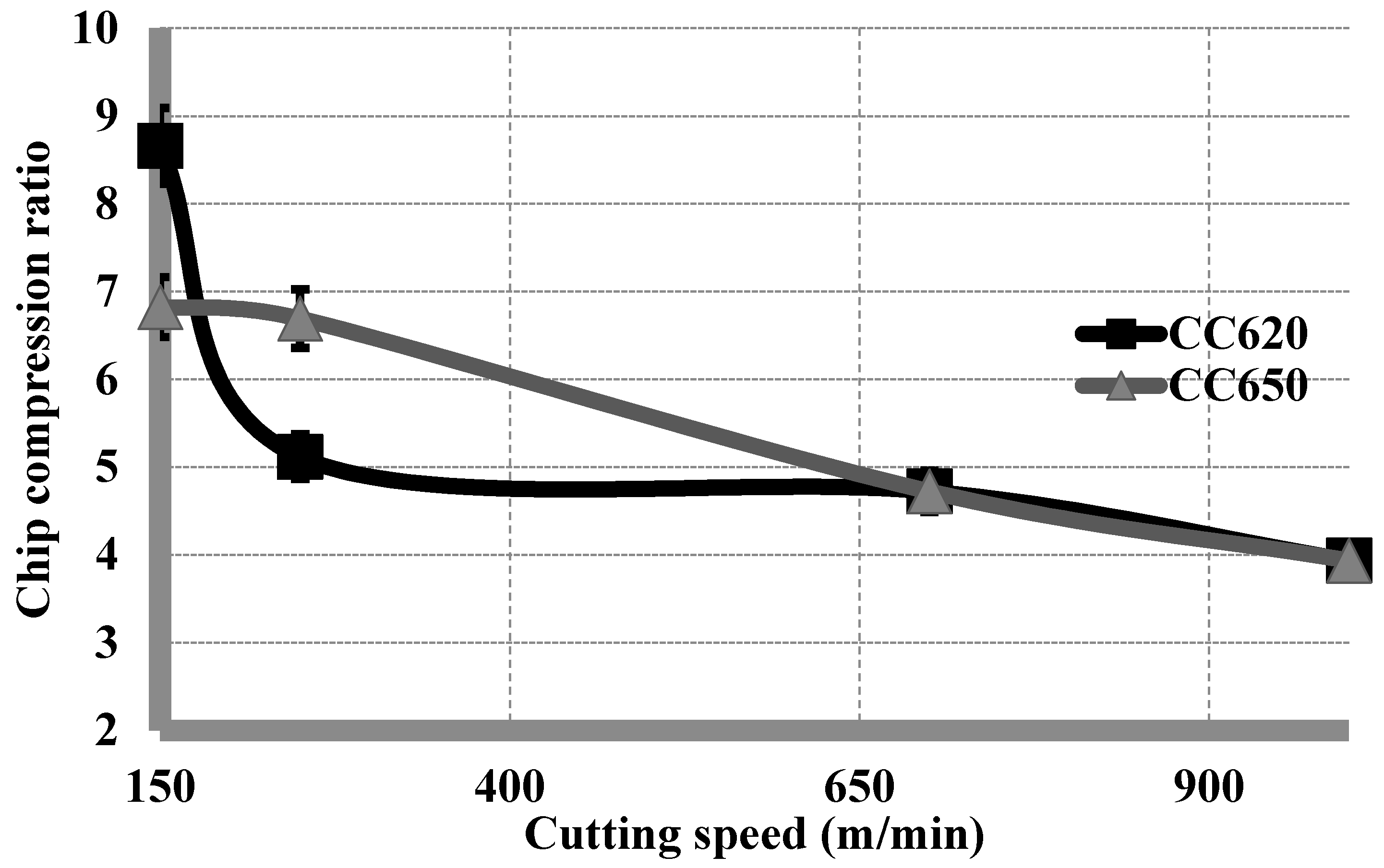
Chip compression ratio is defined as the ratio between the deformed and the undeformed chip thicknesses. This represents the energy spent during plastic deformation occurring during cutting. Therefore, it can be used as an indication of the frictional behavior of the cutting process [26]. The higher values of the chip compression ratio indicate an increase of the coefficient of friction at the tool chip-interface.
Hardened 4340 steel is used in the automotive industry in power transmission shafts and gears. Aircraft landing gears can also be manufactured from the same material. It can be cut at cutting speeds of up to 250 m/min using coated carbide tools [27]. A maximum cutting speed of 420 m/min [28] and 270 m/min [29] have previously been used in the machining of hardened AISI 4340 steel using ceramic tools. Thermally enhanced cutting can be used at higher speeds, but with greater costs and complications [30].
According to the literature, alumina-based ceramic tools are one of the optimal choices for machining hardened steels due to their high hot hardness and chemical stability. The objective of the present work is to investigate the performance of the pure alumina ceramic with the addition of ZrO2 and the mixed alumina (Al2O3 + TiC) tools in the high-speed dry turning of AISI 4340 steel, hardened to 52 HRC. No previous work has considered the effect of tribo-chemical reactions in the cutting region on tool wear resistance at the selected machining conditions. The range of the cutting speeds at which the cutting force components decrease, needs to be explored. The exploration of this range is essential to have the beneficial effects of HSM [31]. Chip compression ratio can be used to find the effect of the used machining conditions on the coefficient of friction at the tool-chip interface.
This work can be utilized for optimization of this HSM operation for the sake of reducing the total machining cost. The optimization methodology has to consider that the hourly cost for modern machining centers is considerably higher than that of the cutting tools. This supports the application of HSM, regardless the expected short tool life obtained at the very high cutting speeds [31].
2. Experimental Work
Bars of AISI 4340 steel 120 mm in diameter, and 600 mm in length, hardened to 52 HRC, were used as the workpiece material in this work. Their chemical composition is presented in Table 1.
The ceramic cutting tools used were pure alumina ceramic with the addition of ZrO2, CC620, and mixed alumina (Al2O3 + TiC), CC650. The two types of tools were mounted on the same tool holder and had the same geometrical configurations except for the chamfering width, which is wider in CC620 than in CC650. The higher chamfering width of CC620 was performed by the manufacturer to increase the strength of the cutting edge of the pure alumina ceramic tool to alleviate fracture and chipping that may occur during cutting. This chamfering width difference would not affect the comparative results, as the used depth of cut was smaller than the chamfering width of both tools. Table 2 illustrates complete descriptions of the used ceramic tool materials and tool holder.
Four cutting speeds—150, 250, 700 and 1000 m/min—were used. The tool nose radius was 1.2 mm. The depth of cut and feed were 0.125 mm and 0.1 mm/rev, respectively. Using feeds in the range of finishing operation can help to reduce the amount of residual stresses on the machined surface, especially in dry cutting [32]. This feed would produce surface roughness values that are close to the values attained by cylindrical grinding (0.35–0.4 μm, Ra). Machining tests were carried out on an Okuma CNC centre lathe. A digital tool maker’s microscope, with a resolution of 0.01 mm, was used to measure the tool flank wear land width. Machining tests were stopped at 0.2 mm flank wear to avoid any adverse effect on the workpiece accuracy and the surface roughness [33]. Wear curves were plotted against the machining time, in minutes. The presented values of tool flank wear were based on the average value of three different measurements; the uncertainty of the measurements was 6%. Scanning electron microscope (SEM) was used to study the wear patterns of the ceramic cutting tools at the different used cutting speeds.
To determine the deformed chip thickness, the produced chips were collected, and their thicknesses were measured three times at three different areas, using a digital micrometer, with 10 μm resolution. The uncertainty of the carried out measurements of the chip thickness was around 5%. The average undeformed chip thickness was calculated based on a previously published work [34]. The ratio between the deformed to the undeformed chip thickness was used to express the “chip compression ratio”.
X-ray photoelectron spectroscopy (XPS) was used to study the tribo-films formed due to the phase transformations occurred at the cutting tool/chip interface. The XPS equipment consisted of a Physical Electronics (PHI) Quantera II spectrometer with a hemispherical energy analyzer, an Al anode source for X-ray generation, and a quartz crystal monochromatic for focusing the generated X-rays. The samples were sputter-cleaned before collecting the data. The beam for data collecting was 100 micrometers, and all spectra were obtained at a 45° take off-angle. The neutralization of all samples was ensured.
Using fresh cutting edges, cutting force components were measured three times by a 3-component tool force Kistler dynamometer with a data acquisition system. The resolution of the used dynamometer is 0.1 N. The forces’ signals were captured by Kistler 5010-type amplifier and then recorded on a computer using LABVIEW software. The plotted values of the forces were the averages of the three experiments, with uncertainty of 2%.
3. Results and Discussion
3.1. Wear Curves
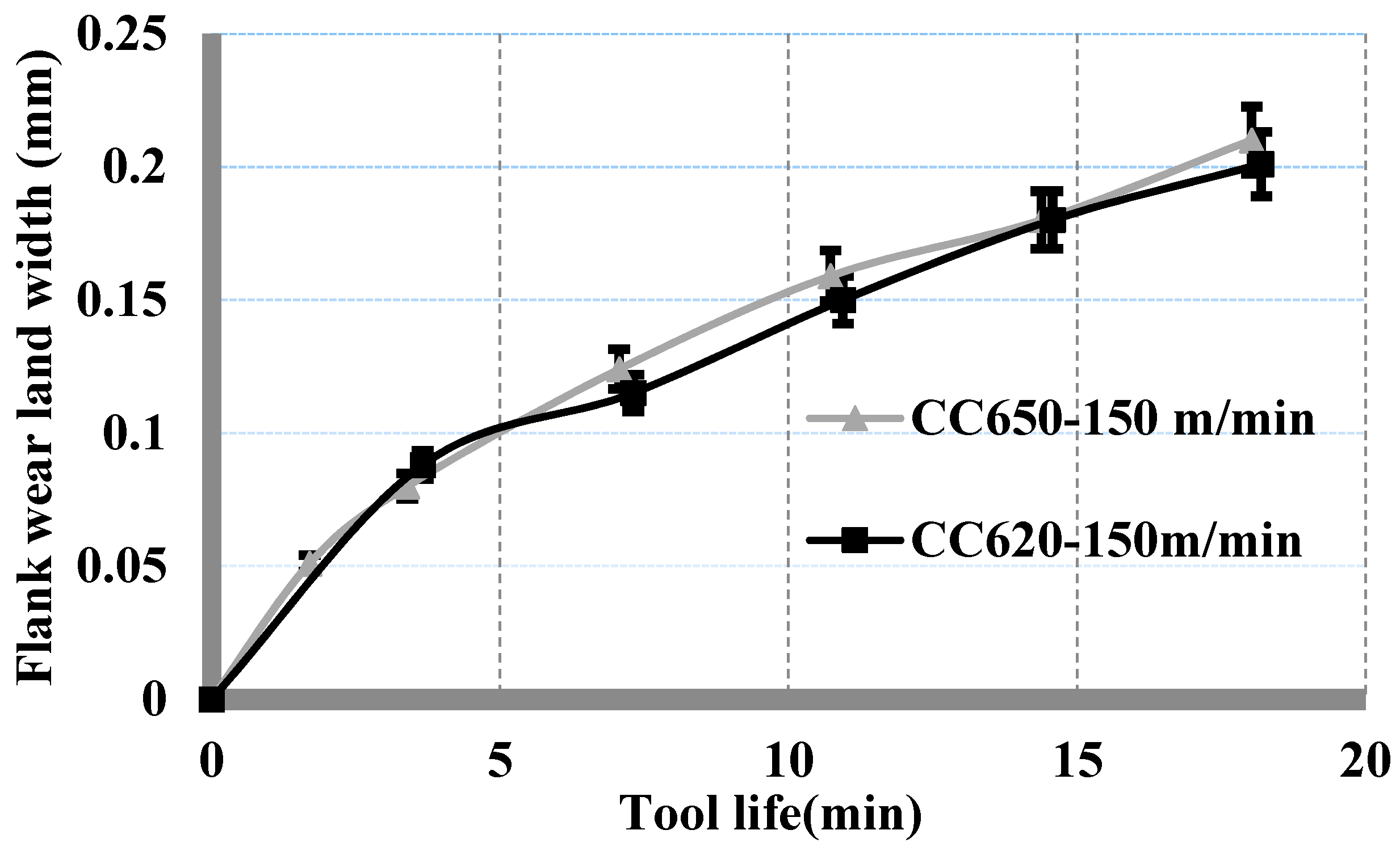
Figure 1 illustrates the wear curves of the used ceramic tools at 150 m/min. The behavior of the curves was almost the same, but tool life was slightly longer using CC620 compared to CC650 (18 min for CC620, 17 min for CC650).
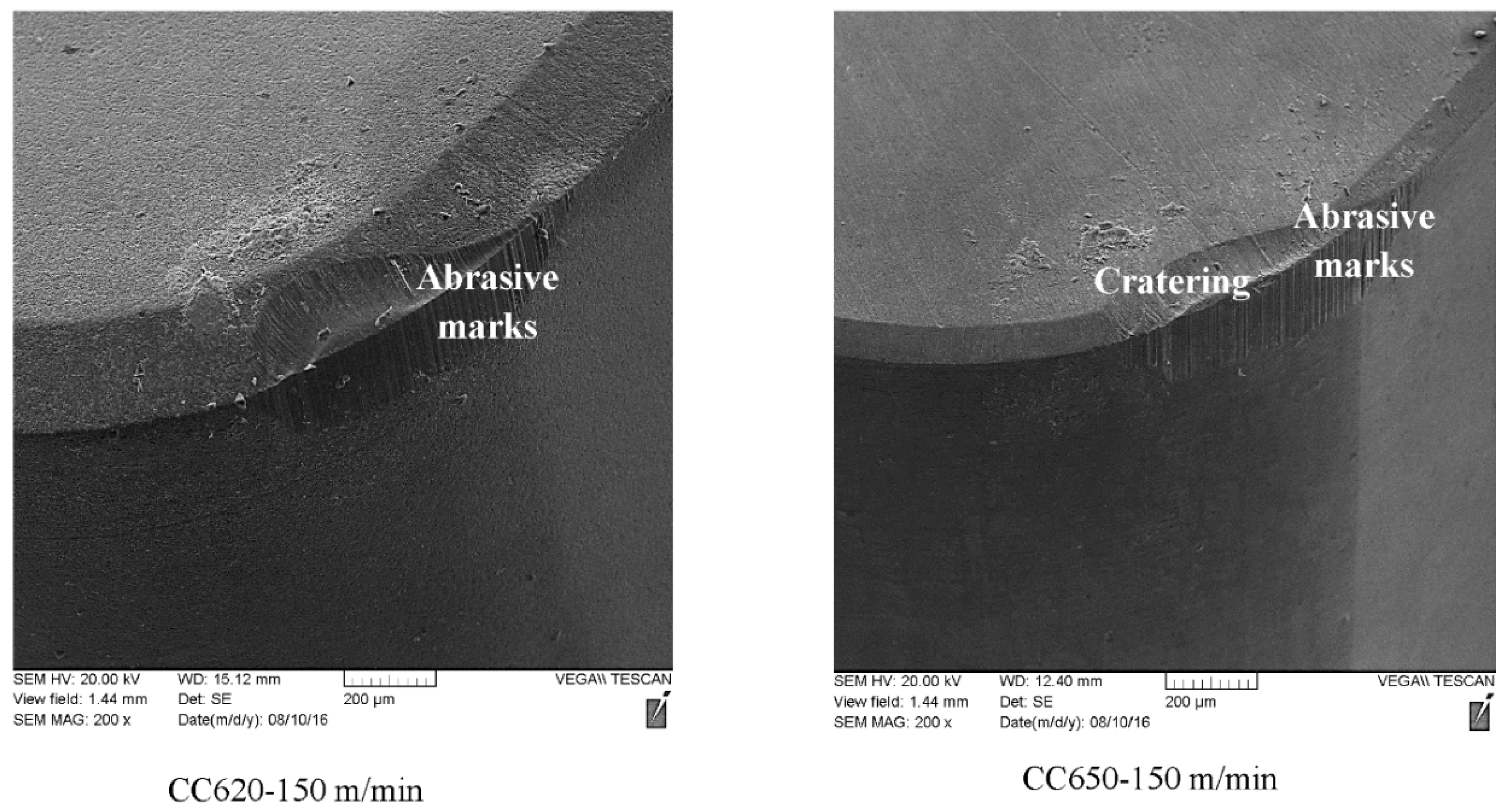
In Figure 2, cratering at the chamfered edge of CC650 was noted, which was not present in CC620. This indicates a higher chemical stability of CC620 compared to CC650 containing 30% of TiC with higher solubility in iron [35]. The abrasive wear mechanism could be deduced from the abrasive marks on the tools flank of each tool.
Increasing the cutting speed to 250 m/min resulted in a markedly longer tool life for CC620 than for CC650 (12 min for CC620, 9 min for CC650), this was indicated in Figure 3. In Figure 4, crater wear was more obvious on CC650 than on CC620. Abrasive marks were present for the two types of tools.
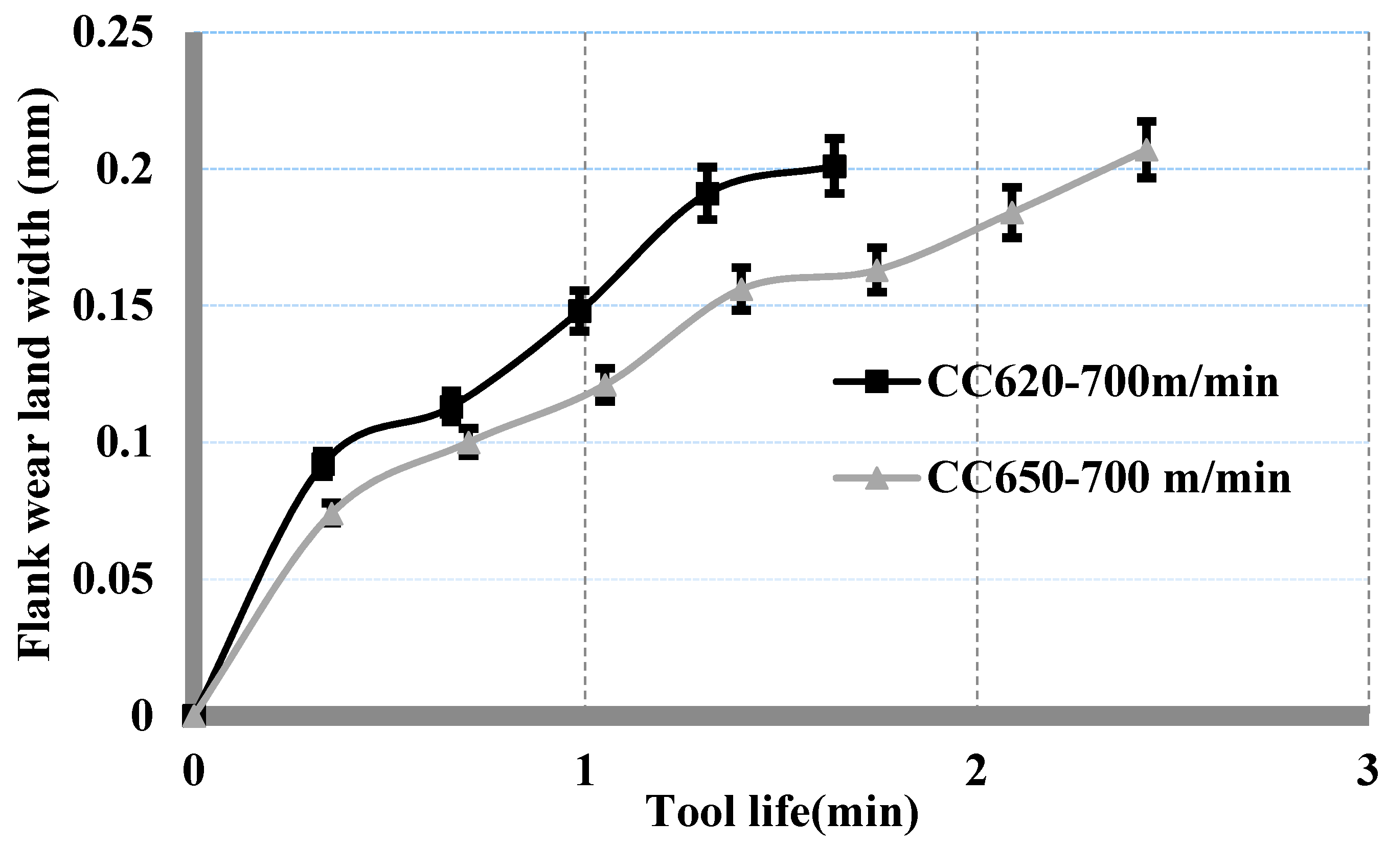
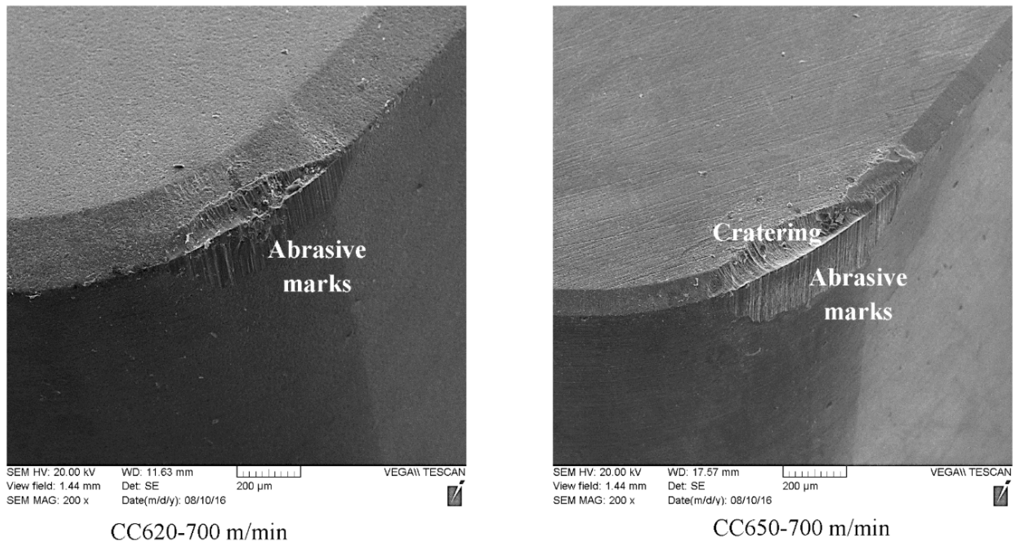
At a cutting speed of 700 m/min, CC650 outperformed CC620 (2.3 min tool life for CC650, 1.6 min tool life for CC620), as presented in Figure 5. As observed before, Figure 6 shows cratering occurred at the chamfered edge of CC650, while this cratering was not present in CC620.
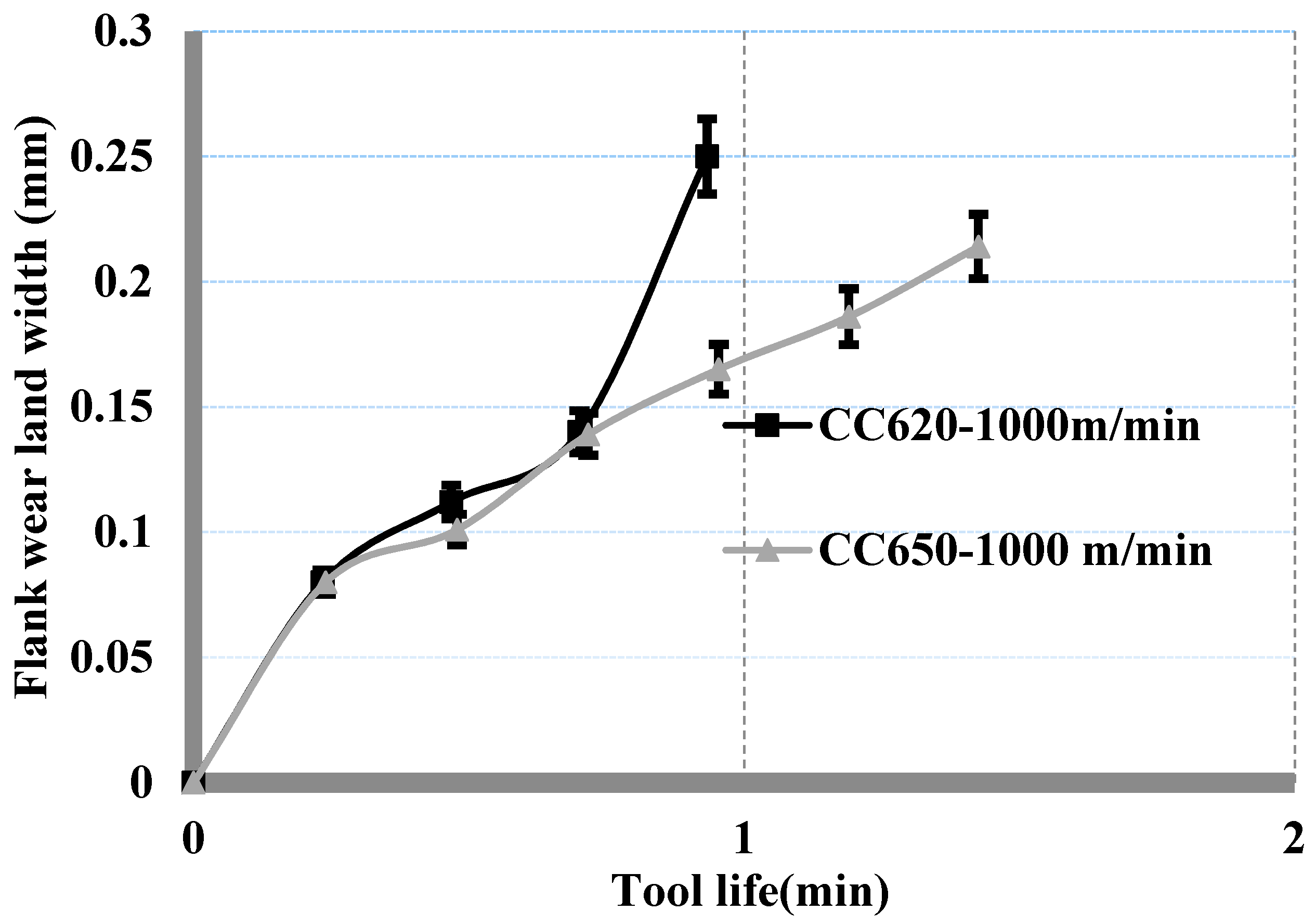
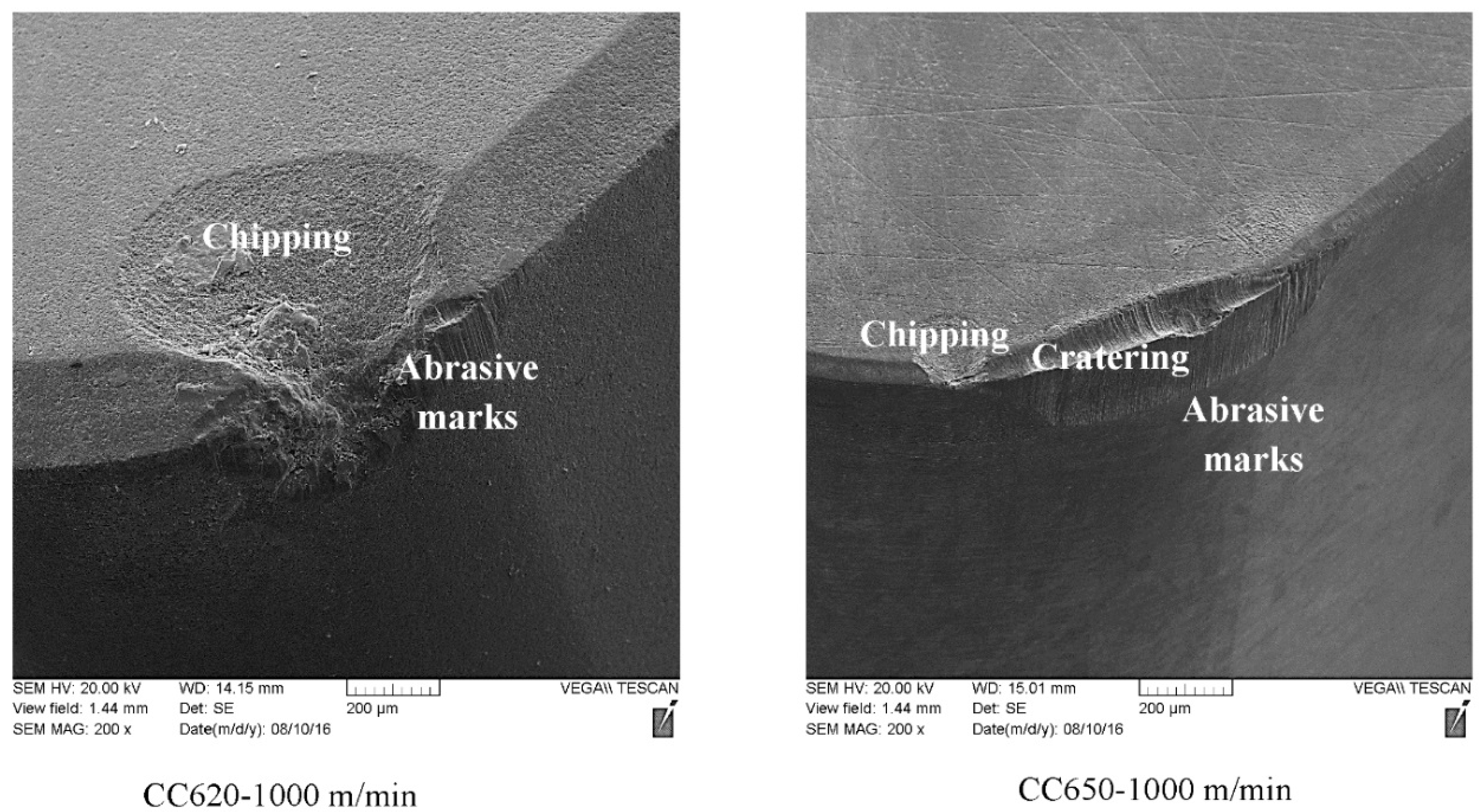
At 1000 m/min, a catastrophic tool failure was observed in CC620 after 0.7 min of machining, Figure 7. In the same figure, CC650 continued with a gradual wear behavior approaching a tool life of 1.4 min. Figure 8 shows the SEM micrographs of the cutting tools after machining at 1000 m/min, illustrating a complete chipping of the cutting edge of CC620. In contrast, CC650 exhibited crater wear, and a small chipping area at the main cutting edge of the insert was present.
It can be concluded that CC620 (pure alumina with the addition of ZrO2) demonstrates superior wear resistance at cutting speeds of 150 and 250 m/min. However, under ultra-high speed values (700, 1000 m/min), CC650 (mixed alumina, Al2O3 + TiC) is recommended. Analysis of these results was carried out through chip study and XPS.
3.2. Chip Study
The effect of the cutting speed on the chip compression ratio is presented in Figure 9. At 150 m/min, CC620 had a higher value than CC650 (9 for CC620, 7 for CC650). This is due to the higher hardness of CC650, which affects the tribological behavior at the tool-chip interface. The increase in the hardness of frictional surfaces during dry friction, reduces the value of the resulted coefficient of friction [20]. Upon reaching a cutting speed of 250 m/min, a remarkable decrease of the chip compression ratio value produced by CC620 was observed (from 9 to 5), while the chip compression value for CC650 was 6.7. At 700 and 1000 m/min, the values of the chip compression ratio were the same for the used ceramic tools (4.7 at 700 m/min, 3.9 at 1000 m/min).
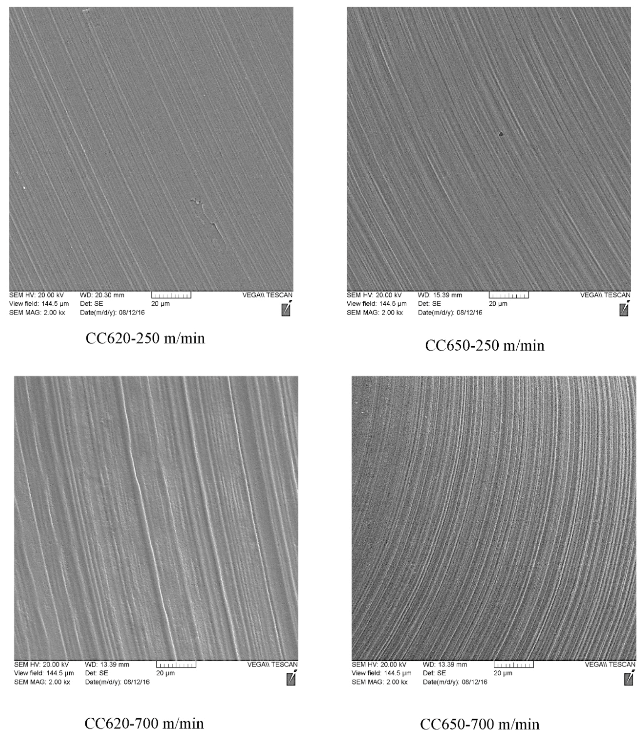
The intensity of the adhesive marks at the chip undersides can be used as an indication of the severity of the adhesive wear mechanism [36]. However, selected chip underside micrographs were presented in Figure 10. At 250 m/min, the intensity of the adhesive marks on the chip underside produced by CC620 was less than the intensity of these marks on the chip underside produced by CC650. At 700 m/min, CC650 produced less intense adhesive marks than CC620. The results deduced from Figure 10 are in agreement with the results obtained from the chip compression ratio curves presented in Figure 9 and the wear curves in Figure 3 and Figure 5.
However, it’s worth mentioning that increasing cutting speed decreased the chip compression ratio and, consequently, the coefficient of friction at the tool-chip interface. This can be considered as an advantage of applying HSM on the hardened AISI 4340 steel.
3.3. XPS Analyses
The higher performance of CC620 at 250 m/min, and the better wear resistance of CC650 at 700 m/min led to performing XPS analysis for these tools at the aforementioned cutting speeds.
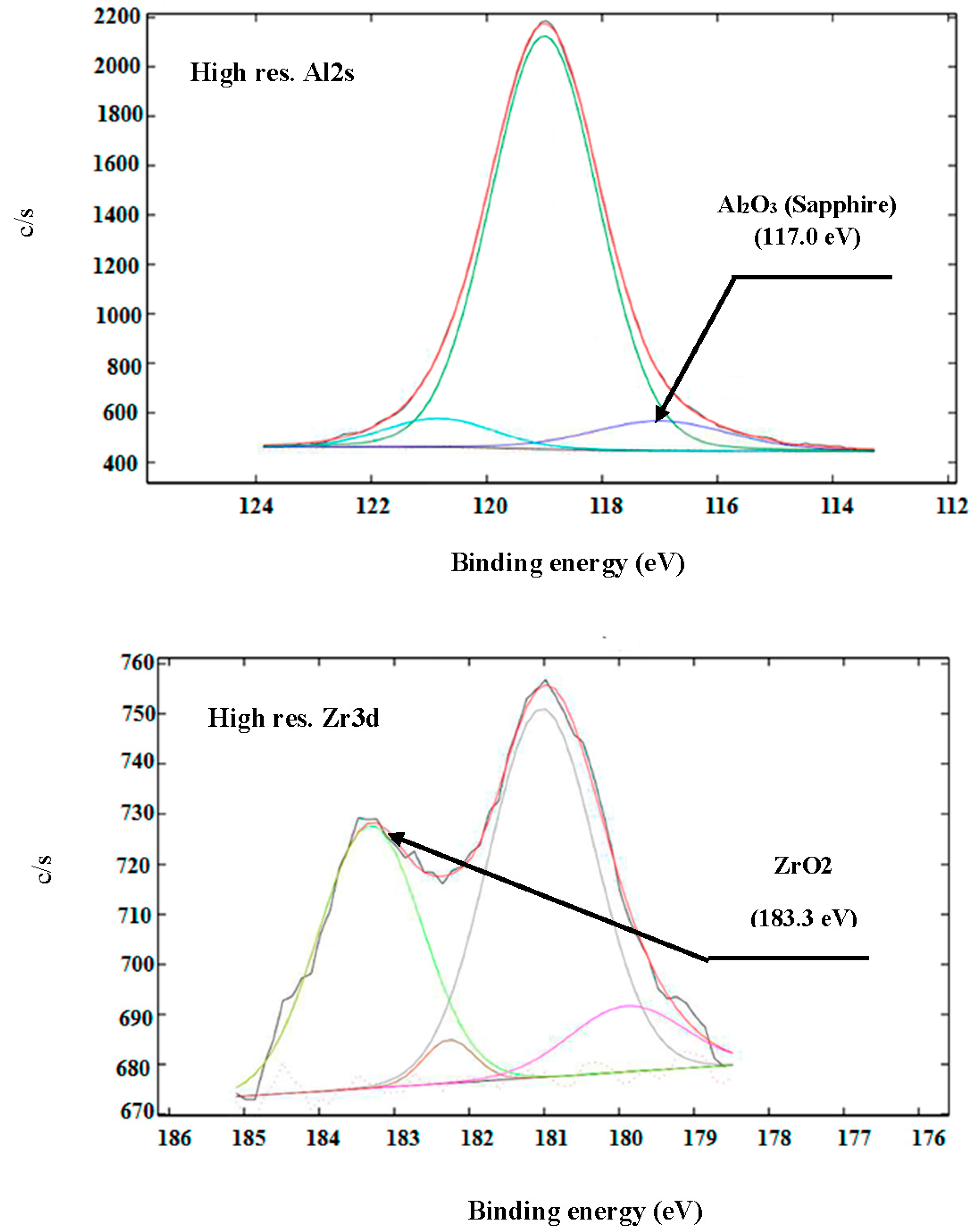
XPS spectra of CC620 at 250 m/min are presented in Figure 11. An adequate amount of alumina (Al2O3) tribo-film with sapphire crystal structure was found (HR Al2s spectrum, binding energy of 117 eV). This tribo-film acts as a thermal barrier at elevated cutting temperatures prevents heat penetration to the tool surface and subsurface that can cause the tool damage; moreover, this tribo-film formation reduces the adhesive wear effect [20]. ZrO2 tribo-film was detected in Figure 11 (HR Zr3d spectrum, binding energy of 183.3 eV). Its formation decreases the coefficient of friction at the tool-chip interface [37]. The detection of these tribo-films supported the results obtained from the wear curve at 250 m/min in Figure 3, chip compression ratio presented in Figure 9, and the chip underside micrographs illustrated in Figure 11. When the cutting speed reaches 700 m/min, ZrO2 tribo-film becomes ineffective due to the expected increase of the cutting temperature to more than 900 °C. This was shown by the wear curve in Figure 5.
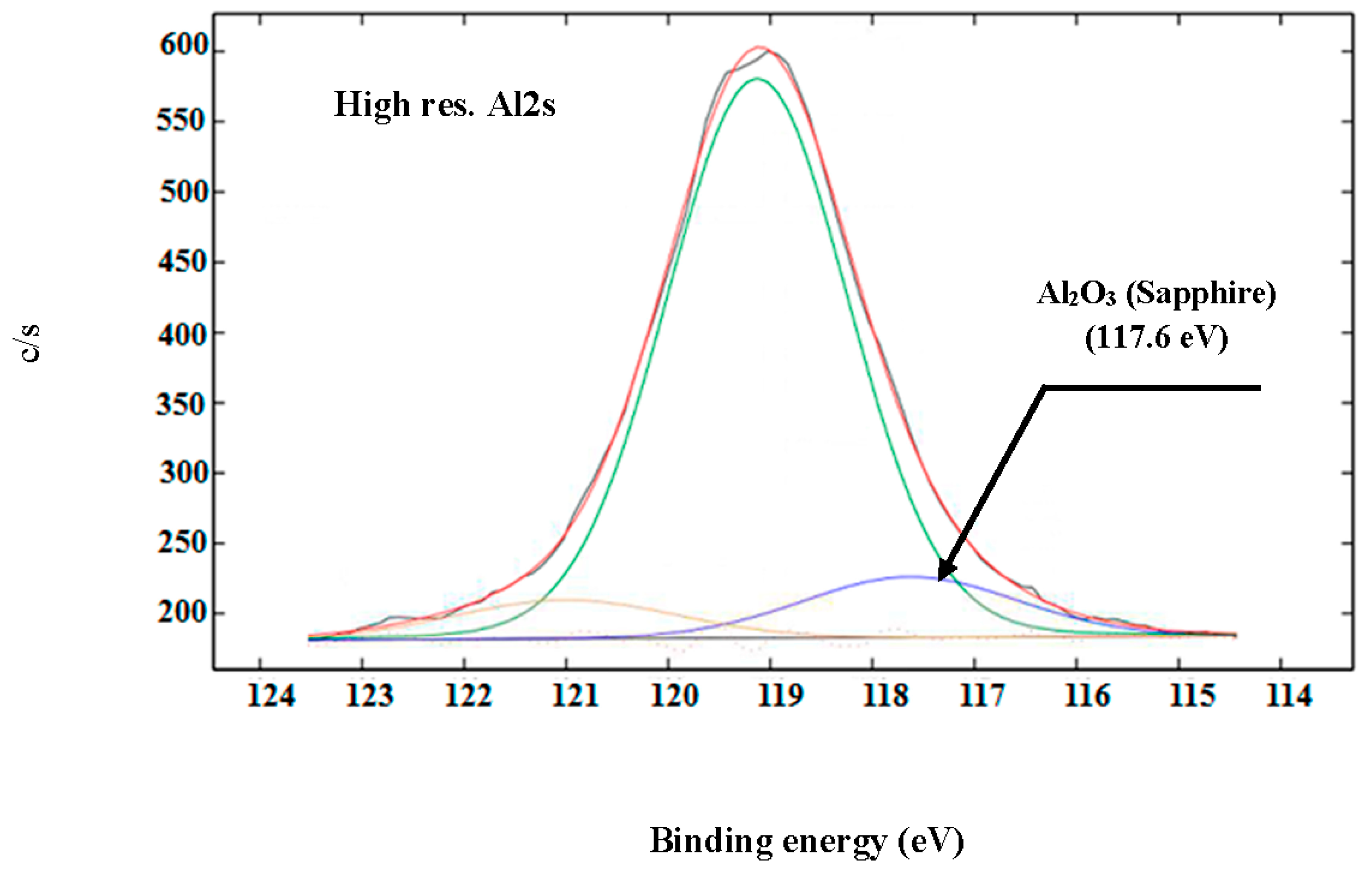
The XPS spectra of CC650 at 700 m/min are shown in Figure 12. An alumina-based layer with sapphire crystal structure was detected (HR Al2s region, binding energy of 117.6 eV). The amount was higher than that found on CC620 at 250 m/min (10.8% compared with 8.3% for CC620 at 250 m/min). This helps the CC650 ceramic tool have longer tool life than CC620 for cutting at this high a speed. Moreover, as indicated in Table 2, CC650 has higher hot hardness and thermal conductivity than CC620, which also enhances its wear resistance.
3.4. Cutting Force Component Measurement
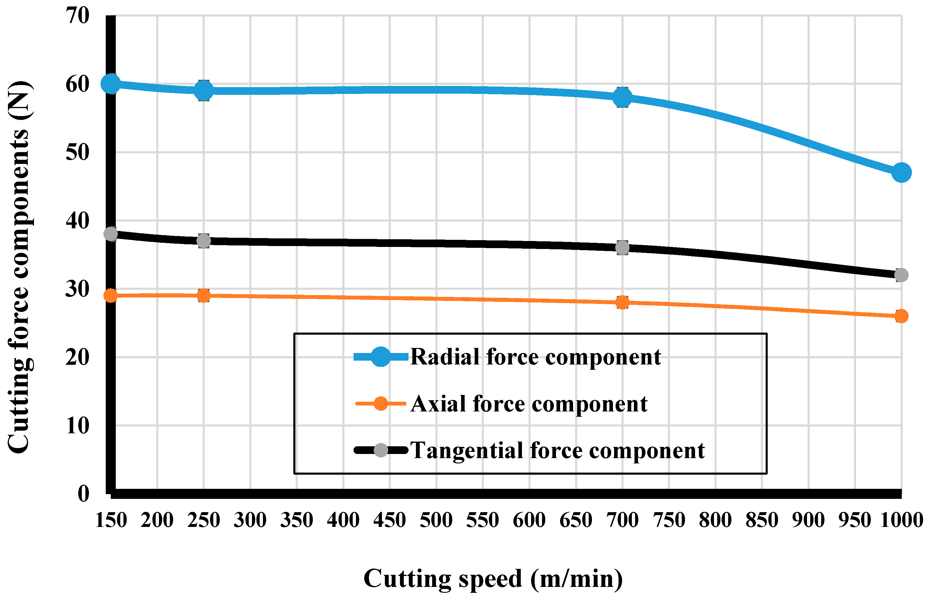
The effect of the cutting speed on the cutting force components when using the CC650 cutting tool is presented in Figure 13. The radial force component was the largest component due to the increased value of the tool nose radius (1.2 mm) when compared to the depth of cut (0.125 mm) [34]. All the components showed a steady behavior with no remarkable reduction in their values until cutting speed reached 700 m/min. By increasing the cutting speed to 1000 m/min, the radial and the tangential force components decreased by 20% and 12%, respectively, which can be attributed to the thermal softening effect. The reduction in the cutting force components and the chip compression ratio upon increasing the cutting speed to 1000 m/min, indicated the decrease of the coefficient of friction at the tool-chip interface when HSM is applied.
4. Conclusions
Several novel observations were noted in the dry high-speed hard turning of AISI 4340 using alumina-based ceramic tools. At cutting speeds of 150 and 250 m/min, the pure alumina ceramic tools with the addition of ZrO2 have higher wear resistance than the mixed alumina tools. XPS analysis carried out on the worn area of the pure alumina ceramic tool at 250 m/min showed the formation of a protective alumina tribo-film with sapphire crystal structure as well as a ZrO2 tribo-film that decreased the coefficient of friction at the tool-chip interface. This was indicated by the chip compression ratio results and the chip underside micrographs. Increasing cutting speed to 700 m/min diminishes the protective effect of the ZrO2 tribo-film when using the pure alumina tools as indicated by the wear curve and the chip compression ratio at this speed. A higher amount of sapphire formed at the worn edge of the mixed alumina ceramic tool at 700 m/min. Moreover, this tool has a higher hardness and thermal conductivity than the pure alumina ceramic tool. Taking these factors into account, the mixed alumina ceramic tool outperforms the pure alumina one at 700 and 1000 m/min. The increase of the cutting speed from 700 to 1000 m/min demonstrated a reduction in the radial force component by 20% and the tangential force component by 12%, which could potentially improve the workpiece accuracy. The value of the cutting force components and chip compression ratio, indicated a decrease of the coefficient of friction at the tool-chip interface upon applying HSM.
Author Contributions
M.S. designed, performed relevant experiments and wrote the manuscript; S.V. supervised the experiments and reviewed the manuscript. The coauthors have read and approved the final manuscript.
Funding
This research was supported by Natural Sciences and Engineering Research Council of Canada (NSERC) under the Canadian Network for Research and Innovation in Machining Technology (CANRIMT) Strategic Research Network Grant NETGP 479639-15.
Acknowledgments
The authors would like to thank G.S. Fox-Rabinovich and G. Dosbaeva from McMaster University for all of their assistances.
Conflicts of Interest
The authors declare no conflict of interest.
References
- Kumar, A.; Durai, A.; Sornakumar, T. Wear behaviour of alumina-based ceramic cutting tools on machining steels. Tribol. Int. 2006, 39, 191–197. [Google Scholar] [CrossRef]
- Schulz, H.; Moriwaki, T. High-speed Machining. CIRP Ann. Manuf. Technol. 1992, 41, 637–643. [Google Scholar] [CrossRef]
- Tönshoff, H.; Arendt, C.; Ben Amor, R. Cutting of hardened steels. CIRP Ann. Manuf. Technol. 2000, 49, 547–566. [Google Scholar] [CrossRef]
- Lima, F.F.; Sales, W.F.; Costab, E.S.; Silva, F.J.; Machadob, A.Á.R. Wear of ceramic tools when machining Inconel 751 using argon and oxygen as lubri-cooling atmospheres. Ceram. Int. 2017, 43, 677–685. [Google Scholar] [CrossRef]
- Yoon, H.S.; Kim, E.S.; Min, S.K.; Lee, J.Y.; Lee, G.B.; Ahn, S.H. Towards greener machine tools—A review on energy saving strategies and technologies. Renew. Sustain. Energy Rev. 2015, 48, 870–891. [Google Scholar] [CrossRef]
- Fernández-Valdivielso, A.; López de Lacalle, L.N.; Urbikain, G.; Rodriguez, A. Detecting the key geometrical features and grades of carbide inserts for the turning of nickel-based alloys concerning surface integrity. Proc. IMechE Part C J. Mech. Eng. Sci. 2016, 230, 3725–3742. [Google Scholar] [CrossRef]
- Ferreira, R.; Řehor, J.; Lauro, C.H.; Carou, D.; Davim, J.P. Analysis of the hard turning of AISI H13 steel with ceramic tools based on tool geometry: Surface roughness, tool wear and their relation. J. Braz. Soc. Mech. Sci. Eng. 2016, 38, 2413–2420. [Google Scholar] [CrossRef]
- Panda, A.; Sahoo, A.K.; Rout, A.K.; Kumar, R.; Das, R.K. Investigation of flank wear in hard turning of AISI 52100 grade using multilayer coated carbide and mixed ceramic inserts. Procedia Manuf. 2018, 20, 365–371. [Google Scholar] [CrossRef]
- Kumar, R.; Shoo, A.K.; Mishra, P.C.; Das, R.K. Comparative investigation towards machinability improvement in hard turning using coated and uncoated carbide inserts: Part I experimental investigation. Adv. Manuf. 2018, 6, 52–70. [Google Scholar] [CrossRef]
- Grzesik, W. Wear development on wiper Al2O3–TiC mixed ceramic tools in hard machining of high strength steel. Wear 2009, 266, 1021–1028. [Google Scholar] [CrossRef]
- Fox-Rabinovich, G.; Gershman, I.; El Hakim, M.; Shalaby, M.; Krzanowski, J.; Veldhuis, S. Tribofilm Formation as a Result of Complex Interaction at the Tool/Chip Interface during Cutting. Lubricants 2014, 2, 113–123. [Google Scholar] [CrossRef]
- Fei, Y.H.; Huang, C.Z.; Liu, H.L.; Zou, B. Mechanical properties of Al2O3–TiC–TiN ceramic tool materials. Ceram. Int. 2014, 40, 10205–10209. [Google Scholar] [CrossRef]
- North, B. Ceramic Cutting Tools. Int. J. High Technol. Ceram. 1987, 3, 113–127. [Google Scholar] [CrossRef]
- Brandt, G. Flank and crater wear mechanisms of alumina-based cutting tools when machining steel. Wear 1986, 112, 39–56. [Google Scholar] [CrossRef]
- Cui, X.; Wang, D.; Guo, J. Influences of tool rake angle and cutting speed on ceramic tool failure in continuous and intermittent turning of hardened steel. Ceram. Int. 2016, 42, 12390–12400. [Google Scholar] [CrossRef]
- Komanduri, R. Advanced ceramic tool materials for machining. Sadhana 1988, 13, 119–137. [Google Scholar] [CrossRef]
- Bushlya, V.; Zhou, J.; Avdovic, P.; Ståhl, J. Wear mechanisms of silicon carbide-whisker-reinforced alumina (Al2O3–SiCw) cutting tools when high-speed machining aged Alloy 718. Int. J. Adv. Manuf. Technol. 2013, 68, 1083–1093. [Google Scholar] [CrossRef]
- Brandt, G.; Gerendas, A.; Mikus, M. Wear mechanisms of Ceramic Cutting Tools When machining Ferrous and Non-ferrous alloys. J. Eur. Ceram. Soc. 1990, 6, 273–290. [Google Scholar] [CrossRef]
- Abukhshim, N.A.; Mativenga, P.T.; Sheikh, M.A. Heat generation and temperature prediction in metal cutting: A review and implications for high speed machining. Int. J. Mach. Tools Manuf. 2006, 46, 782–800. [Google Scholar] [CrossRef]
- Fox-Rabinovich, G.; Yamamoto, K.; Beake, D.; Gershman, S.; Kovalev, A.; Veldhuis, S. Hierarchical adaptive nanostructured PVD coatings for extreme tribological applications: The quest for nonequilibrium states and emergent behavior. Sci. Technol. Adv. Mater. 2012, 13, 043001. [Google Scholar] [CrossRef] [PubMed]
- Fox-Rabinovich, G.; Kovalev, A.; Veldhuis, S.; Yamamoto, K.; Endrino, J.; Gershman, I.; Rashkovskiy, A.; Aguirre, M.; Wainstein, D. Spatio-temporal behaviour of atomic-scale tribo-ceramic films in adaptive surface engineered nano-materials. Sci. Rep. 2015, 5, 8780. [Google Scholar] [CrossRef] [PubMed]
- Yuan, J.; Fox-Rabinovich, G.; Veldhuis, S. Control of tribofilm formation in dry machining of hardened AISI D2 steel by tuning the cutting speed. Wear 2018, 402–403, 30–37. [Google Scholar] [CrossRef]
- Kurt, A.; Yalçin, B.; Yilmaz, N. The cutting tool stresses in finish turning of hardened steel with mixed ceramic tool. Int. J. Adv. Manuf. Technol. 2015, 80, 315–325. [Google Scholar] [CrossRef]
- Archenti, A.; Nicolescu, M.; Casterman, G.; Hjelm, S. A new method for circular testing of machine tools under loaded condition. Procedia CIRP 2012, 1, 575–580. [Google Scholar] [CrossRef]
- Shalaby, M.A.; El Hakim, M.A.; Abdelhameed, M.M.; Veldhuis, S.C. Compensation of deflection-induced errors in high precision hard turning using a piezoelectric-based fast tool servo. In Proceedings of the 6th International Conference on Virtual Machining Process Technology (VMPT), Montréal, QC, Canada, 29 May–2 June 2017. [Google Scholar]
- Thakur, D.G.; Ramamoorthy, B.; Vijayaraghavan, L. Machinability investigation of Inconel 718 in high-speed turning. Int. J. Adv. Manuf. Technol. 2009, 45, 421–429. [Google Scholar] [CrossRef]
- Gunjal, S.U.; Patil, N.G. Experimental investigations into turning of hardened AISI 4340 steel using vegetable based cutting fluids under minimum quantity lubrication. Procedia Manuf. 2018, 20, 18–33. [Google Scholar] [CrossRef]
- Singh, B.K.; Mondal, B.; Mandal, N. Machinability evaluation and desirability function optimization of turning parameters for Cr2O3 doped zirconia toughened alumina (Cr-ZTA) cutting insert in high speed machining of steel. Ceram. Int. 2016, 42, 3338–3350. [Google Scholar] [CrossRef]
- Godoy, V.A.; Diniz, A.E. Turning of interrupted and continuous hardened steel surfaces using ceramic and CBN cutting tools. J. Mater. Process. Technol. 2011, 211, 1014–1025. [Google Scholar] [CrossRef]
- Sun, S.; Brandt, M.; Dargusch, M.S. Thermally enhanced machining of hard-to-machine materials—A review. Int. J. Mach. Tools Manuf. 2010, 50, 663–680. [Google Scholar] [CrossRef]
- Fernández-Abia, A.I.; Barreiro, J.; López de Lacalle, L.N.; Martínez, S. Effect of very high cutting speeds on shearing, cutting forces and roughness in dry turning of austenitic stainless steels. Int. J. Adv. Manuf. Technol. 2011, 57, 61–71. [Google Scholar] [CrossRef]
- Tang, L.; Gao, C.; Huang, J.; Shen, H.; Lin, X. Experimental investigation of surface integrity in finish dry hard turning of hardened tool steel at different hardness levels. Int. J. Adv. Manuf. Technol. 2015, 77, 1655–1669. [Google Scholar] [CrossRef]
- Grzesik, W. Influence of tool wear on surface roughness in hard turning using differently shaped ceramic tools. Wear 2008, 265, 327–335. [Google Scholar] [CrossRef]
- Shalaby, M.; El Hakim, M.; Veldhuis, S.; Dosbaeva, G. An investigation into the behavior of the cutting forces in precision turning. Int. J. Adv. Manuf. Technol. 2017, 90, 1605–1615. [Google Scholar] [CrossRef]
- Jack, D.H. Ceramic cutting tool materials. Mater. Des. 1986, 7, 267–273. [Google Scholar] [CrossRef]
- Shalaby, M.; El Hakim, M.; Abdelhameed, M.; Krzanowski, J.E.; Veldhuis, S.; Dosbaeva, G. Wear mechanisms of several cutting tool materials in hard turning of high carbon–chromium tool steel. Tribol. Int. 2014, 70, 148–154. [Google Scholar] [CrossRef]
- Peterson, M.B.; Li, S.; Murray, S.F. Wear-resisting oxide films for 900 °C. J. Mater. Sci. Technol. 1997, 13, 99–106. [Google Scholar]
Figure 1.
Wear curves of the used alumina-based ceramic tool in hard machining of AISI 4340 steel at 150 m/min.
Figure 1.
Wear curves of the used alumina-based ceramic tool in hard machining of AISI 4340 steel at 150 m/min.

Figure 2.
SEM micrographs of the used alumina-based ceramic tool in hard machining of AISI 4340 steel at 150 m/min.
Figure 2.
SEM micrographs of the used alumina-based ceramic tool in hard machining of AISI 4340 steel at 150 m/min.

Figure 3.
Wear curves of the used alumina-based ceramic tool in hard machining of AISI 4340 steel at 250 m/min.
Figure 3.
Wear curves of the used alumina-based ceramic tool in hard machining of AISI 4340 steel at 250 m/min.
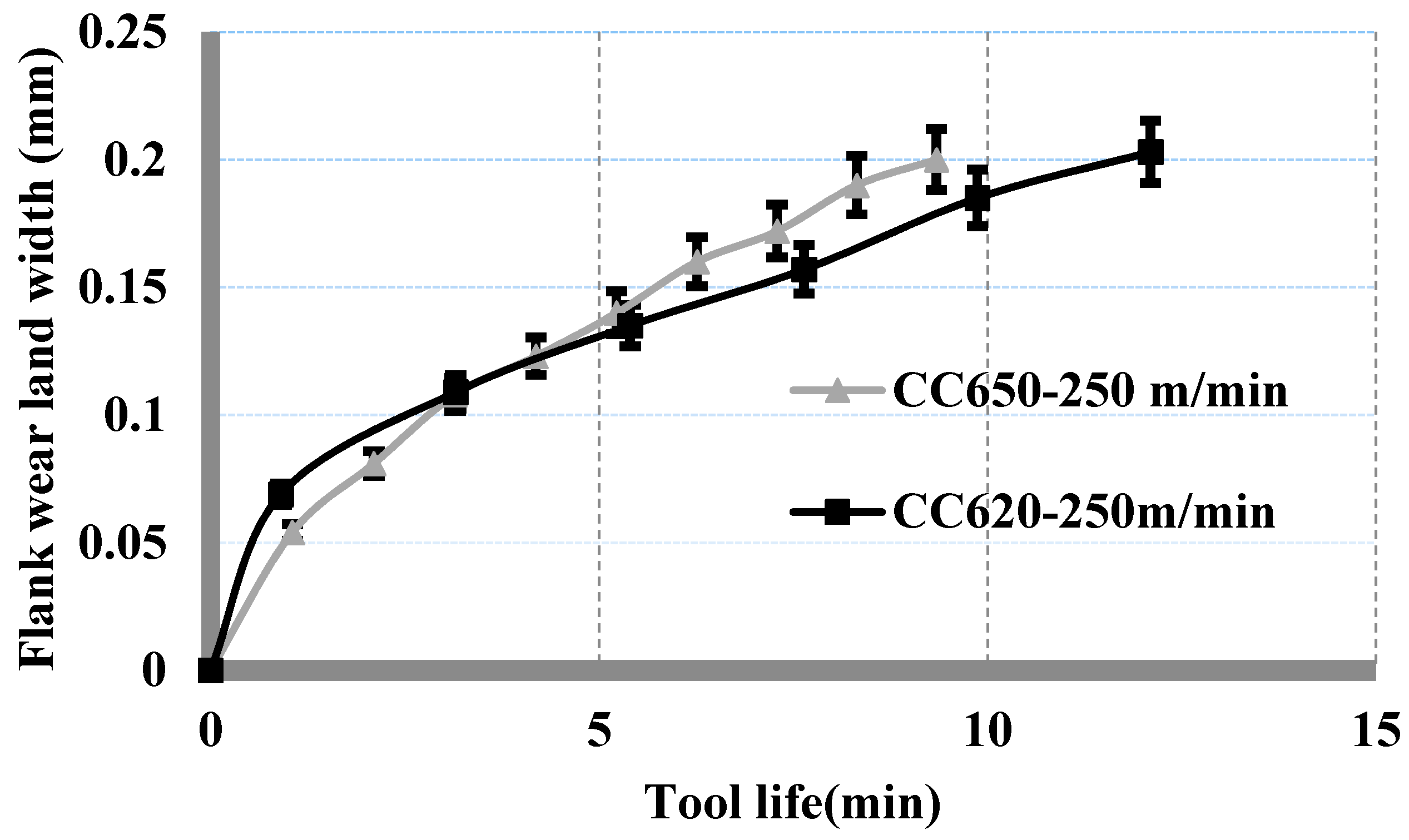
Figure 4.
SEM micrographs of the used alumina-based ceramic tool in hard machining of AISI 4340 steel at 250 m/min.
Figure 4.
SEM micrographs of the used alumina-based ceramic tool in hard machining of AISI 4340 steel at 250 m/min.
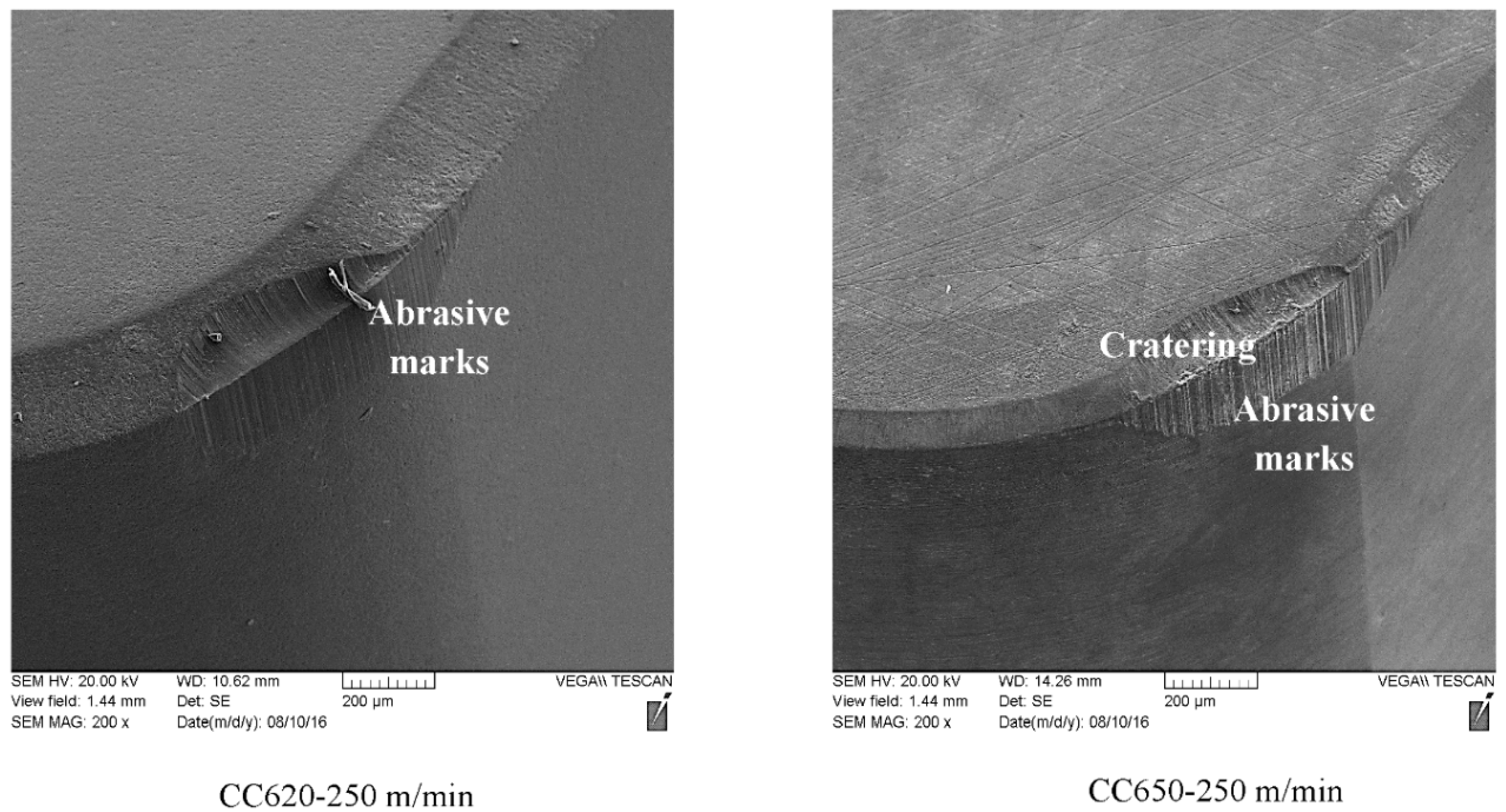
Figure 5.
Wear curves of the used alumina-based ceramic tool in hard machining of AISI 4340 steel at 700 m/min.
Figure 5.
Wear curves of the used alumina-based ceramic tool in hard machining of AISI 4340 steel at 700 m/min.

Figure 6.
SEM micrographs of the used alumina-based ceramic tool in hard machining of AISI 4340 steel at 700 m/min.
Figure 6.
SEM micrographs of the used alumina-based ceramic tool in hard machining of AISI 4340 steel at 700 m/min.

Figure 7.
Wear curves of the used alumina-based ceramic tool in hard machining of AISI 4340 steel at 1000 m/min.
Figure 7.
Wear curves of the used alumina-based ceramic tool in hard machining of AISI 4340 steel at 1000 m/min.

Figure 8.
SEM micrographs of the used alumina-based ceramic tool in hard machining of AISI 4340 steel at 1000 m/min.
Figure 8.
SEM micrographs of the used alumina-based ceramic tool in hard machining of AISI 4340 steel at 1000 m/min.

Figure 9.
Effect of cutting speed on chip compression ratio tool in hard machining of AISI 4340 steel.
Figure 9.
Effect of cutting speed on chip compression ratio tool in hard machining of AISI 4340 steel.

Figure 10.
Chip undersides at different conditions.

Figure 11.
XPS spectra of CC620 at 250 m/min.

Figure 12.
XPS spectra of CC650 at 700 m/min.

Figure 13.
Effect of cutting speed on cutting force components in hard machining of AISI 4340 steel.
Figure 13.
Effect of cutting speed on cutting force components in hard machining of AISI 4340 steel.


Table 1.
Chemical composition of AISI 4340 steel.
| %Mo | %Si | %Mn | %Cr | %Mo | %Ni | %Fe |
|---|---|---|---|---|---|---|
| 0.37–0.43 | 0.15–0.3 | 0.6–0.8 | 0.7–0.9 | 0.2–0.3 | 1.65–2.00 | Balance |
Table 2.
Description of the used ceramic tool materials and tool holder.
| Ceramic Tool | Chemical Composition | Hardness | Thermal Conductivity | Tool Holder |
|---|---|---|---|---|
| Pure alumina with the addition of ZrO2(CC620) | Al2O3 (95%) + ZrO2 (5%) | 1800 Hv at 25 °C 600 Hv at 1000 °C | 22 W/mK at 25 °C 7 W/mK at 1000 °C | Rake angle = −6° Clearance angle = 5°  |
| Mixed alumina (CC650) | Al2O3 (70%) + TiC (30%) | 2000 Hv at 25 °C 750 Hv at 1000 °C | 25 W/mK at 25 °C 12 W/mK at 1000 °C |
© 2018 by the authors. Licensee MDPI, Basel, Switzerland. This article is an open access article distributed under the terms and conditions of the Creative Commons Attribution (CC BY) license (http://creativecommons.org/licenses/by/4.0/).
Share and Cite
MDPI and ACS Style
Shalaby, M.; Veldhuis, S. New Observations on High-Speed Machining of Hardened AISI 4340 Steel Using Alumina-Based Ceramic Tools. J. Manuf. Mater. Process. 2018, 2, 27. https://doi.org/10.3390/jmmp2020027
AMA Style
Shalaby M, Veldhuis S. New Observations on High-Speed Machining of Hardened AISI 4340 Steel Using Alumina-Based Ceramic Tools. Journal of Manufacturing and Materials Processing. 2018; 2(2):27. https://doi.org/10.3390/jmmp2020027
Chicago/Turabian StyleShalaby, Mohamed, and Stephen Veldhuis. 2018. "New Observations on High-Speed Machining of Hardened AISI 4340 Steel Using Alumina-Based Ceramic Tools" Journal of Manufacturing and Materials Processing 2, no. 2: 27. https://doi.org/10.3390/jmmp2020027