Experimental and Modeling Study of Liquid-Assisted—Laser Beam Micromachining of Smart Ceramic Materials


Department of Mechanical Engineering, California State University Fullerton, Fullerton, CA 92831, USA
*
Author to whom correspondence should be addressed.
J. Manuf. Mater. Process. 2018, 2(2), 28; https://doi.org/10.3390/jmmp2020028
Submission received: 4 April 2018
/
Revised: 30 April 2018
/
Accepted: 2 May 2018
/
Published: 7 May 2018
(This article belongs to the Special Issue Precision Manufacturing)
Abstract
:Smart ceramic materials are next generation materials with the inherent intelligence to adapt to change in the external environment. These materials are destined to play an essential role in several critical engineering applications. Machining these materials using traditional machining processes is a challenge. The laser beam micromachining (LBMM) process has the potential to machine such smart materials. However, laser machining when performed in air induces high thermal stress on the surface, often leading to crack formation, recast and re-deposition of ablated material, and large heat-affected zones (HAZ). Performing laser beam machining in the presence of a liquid medium could potentially resolve these issues. This research investigates the possibility of using a Liquid Assisted—Laser Beam Micromachining (LA-LBMM) process for micromachining smart ceramic materials. Experimental studies are performed to compare the machining quality of laser beam machining process in air and in a liquid medium. The study reveals that the presence of liquid medium helps in controlling the heat-affected zone and the taper angle of the cavity drilled, thereby enhancing the machining quality. Analytical modeling is developed for the prediction of HAZ and cavity diameter both in air and underwater conditions, and the model is capable of predicting the experimental results to within 10% error.
1. Introduction
Smart ceramic materials are advanced ceramic materials that possess the inherent intelligence to adapt to change in the external environment. Smart ceramic materials primarily fall into three categories: piezoelectric, pyroelectric and ferroelectric materials. Piezoelectric ceramics can generate a voltage on their surface when stressed and, conversely, stress is developed when a voltage is applied. Piezoelectric ceramics are used extensively in several microdevices, with one example being Microelectromechanical Systems (MEMS). Applications of MEMS include transducers for medical ultrasound diagnostics, actuators in aerospace and automotive components, and energy harvesting and several others [1]. Considering the tremendous applications of MEMS, there is an increasing need for advanced manufacturing techniques capable of micromachining smart ceramic materials. Machining smart ceramic materials is often a huge challenge even at the macroscale. Studies have shown that machining smart ceramics using traditional methods such as drilling or non-traditional processes such as Electro Discharge Machining (EDM), Ultrasonic Milling (USM) is extremely complex, time-consuming, and often results in machining inaccuracies [2].
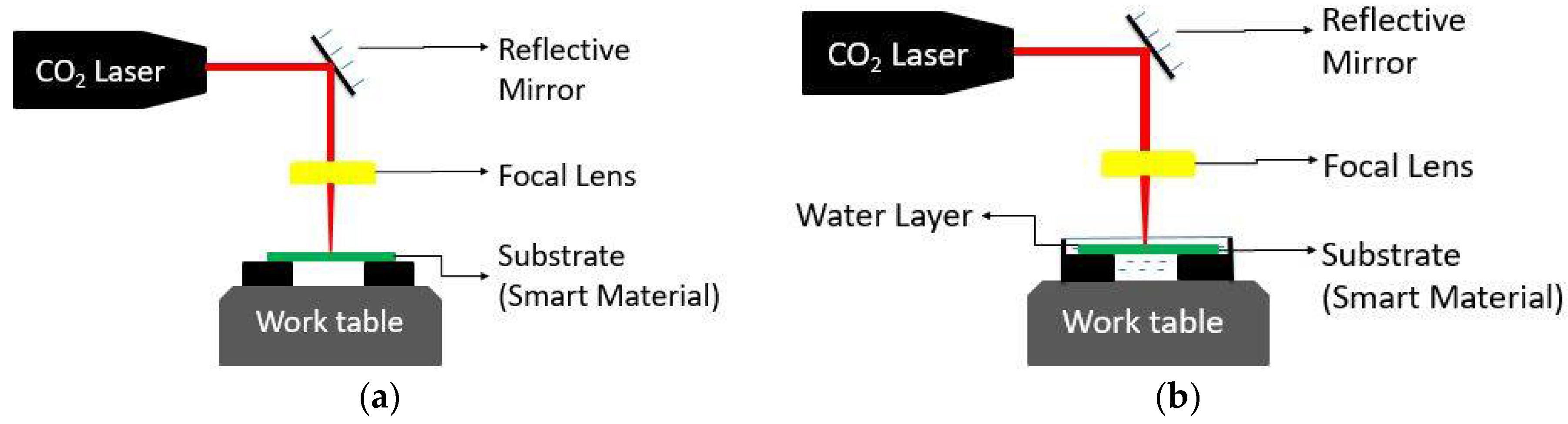
Laser Beam Micromachining (LBMM) is a proven technique in micromachining ceramic materials, considering its ability to remove materials rapidly, without direct tool-workpiece contact, and with high accuracy and precision. Moreover, laser beam micromachining also has the flexibility to fabricate 3D structures [3]. The LBMM process has demonstrated its capability in machining smart ceramic materials at the macroscale [4]. LBMM is performed in air, and it uses the thermal energy of the laser beam to ablate material from metallic or nonmetallic materials, as shown in Figure 1a [5]. The laser beam is directed towards the substrate surface through a focusing lens to obtain a beam with a micron scale spot size. The focused beam then heats, melts and vaporizes the substrate material using its high thermal energy. The laser beam in air induces high temperatures on the surface of the material, thereby increasing the thermal stress. This leads to crack formation, recast and re-deposition of ablated material, and formation of large heat-affected zones [6]. A study on ultraviolet (UV) laser ablation in air showed crater formation with a rim due to re-solidification of the molten piezoelectric ceramic material from the irradiated zone [7]. These limitations of laser beam micromachining in the air can be resolved by integrating a liquid medium such as water, ethylene glycol, and methanol near the machining zone [8]. This process, known as Liquid Assisted—Laser Beam Micromachining (LA-LBMM), is thus used as an alternative to the LBMM process. The schematic of LA-LBMM process is shown in Figure 1b.
An investigation done previously shows that CO2 laser, used for micromachining Pyrex glass, resulted in the formation of micro-cracks in the air due to high thermal stresses. Moreover, no scorches or cracks appeared when machining was performed using Liquid Assisted Laser Processing (LALP) [6]. Experimental investigations were performed to realize the working of the Droplet Assisted Laser Micromachining (DALM) process [9]. Compared to dry Pulse Laser Ablation (PLA) process, the DALM process increased the material removal rate by 75% and reduced the material re-deposition by 70% [9]. Alumina, 8 Yttria-Stabilized Zirconia (8-YSZ) and glass-ceramic substrate were micromachined by laser pulses in nanosecond range using liquid medium as the surrounding. It was observed that when the liquid medium was used, ablation rates were higher than micromachining in air [8]. A study on flowing water ablation of silicon showed much-reduced recast and re-deposition of the ablated material on the groove surface [10]. Furthermore, significant recast formation was noticeable inside the machined groove when the silicon was ablated in ambient air. Unlike in ambient air, the maximum amount of the ejected molten substrate material did not re-solidify on the edges of the crater; instead, it was flushed away by the flowing stream [11]. CO2 laser machining, when performed underwater, was successful for milling deep-crack-free cavities in alumina [12]. It was observed that the machining quality in underwater laser beam machining was improved over that in ambient air. Underwater laser beam machining showed the ability to prevent initiation of cracks, and a reduction in the heat-affected zone (HAZ) due to the cooling effect provided by the water. Based on the literature review, it is understood that the LA-LBMM process can efficiently reduce heat-affected zones, micro-cracks, re-deposition and recasting of ablated material on the surface of the substrate material, as well as significantly improving machined quality when compared to machining in air.
From the literature survey, it was found that the Liquid Assisted—Laser Beam Micromachining (LA-LBMM) process had not yet been used for micromachining smart ceramic materials. Hence, this study focuses on the micromachining of piezoelectric ceramic using Liquid Assisted—Laser Beam Micromachining (LA-LBMM) process. Micro-cavity and heat-affected zone diameters are studied while performing micromachining of piezoelectric ceramic material both in the air and under liquid medium. This research aims to understand the effects of incorporating liquid medium at the machining zone during the micromachining of smart ceramic materials.
2. Analytical Modeling of LA-LBMM Process
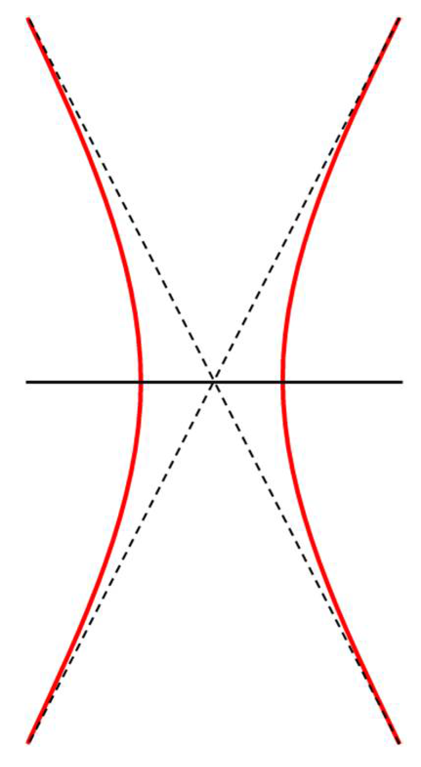
A mathematical model is developed to predict the sizes of the machined cavity and the heat-affected zone during both the LBMM and LA-LBMM process. The laser beam is modeled as heat flux, with its intensity distributed in the form of a Gaussian beam as shown in Figure 2. It is given by the following equation.
where Ia is the laser intensity, Pa is the average power of the laser and R is laser spot radius.
2.1. Analytical Model to Predict Cavity Diameter During LA-LBMM Process
In this analytical study, the size of the cavity machined is considered the area of the substrate surface that undergoes melting and ablation. The effect of material re-deposition is not considered in this model. The radius of the machined cavity (rac) during LBMM process can be expressed as [13]
where αm is the absorption coefficient of substrate material, η is the heat flux efficiency, and Icm is the critical power density required to melt the substrate material. The critical power density (Icm) required for melting is estimated using the equation [14].
where is the heat liberation rate at melting of substrate material, is the substrate density and tm is the substrate thickness.
During the LA-LBMM process, the intensity of the laser beam is reduced due to partial absorption of the laser beam energy in the liquid medium. The quantity of energy reduction can be related to Beer-Lambert’s law of absorption of energy [15]. However, Beer-Lambert’s law is not accurate for predicting the energy loss in the LA-LBMM process, due to the complex photo-thermal interactions between liquid, laser and the substrate material [6]. The average power of the laser in liquid (Pw) can be estimated by introducing a correction factor to Equation (1) as follows [6]
The intensity of the laser beam (Iw) during the LA-LBMM process is determined as
The radius of the machined cavity (rwc) during the LA-LBMM process is calculated as follows
2.2. Analytical Model to Predict HAZ Diameter During LA-LBMM Process
During the laser machining processes, the heat-affected zone (HAZ) is considered to be the area of the machined surface that undergoes chemical and microstructural modifications but does not melt [16]. Critical power density (Ich) for material recrystallization is considered to determine the size of the heat-affected zone. The radius of the HAZ (rah) during the LBMM process can be expressed as
The radius of HAZ (rwh) during the LA-LBMM process can be determined as
The critical power density (Ich) required for material recrystallization is estimated using the equation
where is the heat liberation rate at recrystallization of the substrate material.
3. Experimental Method
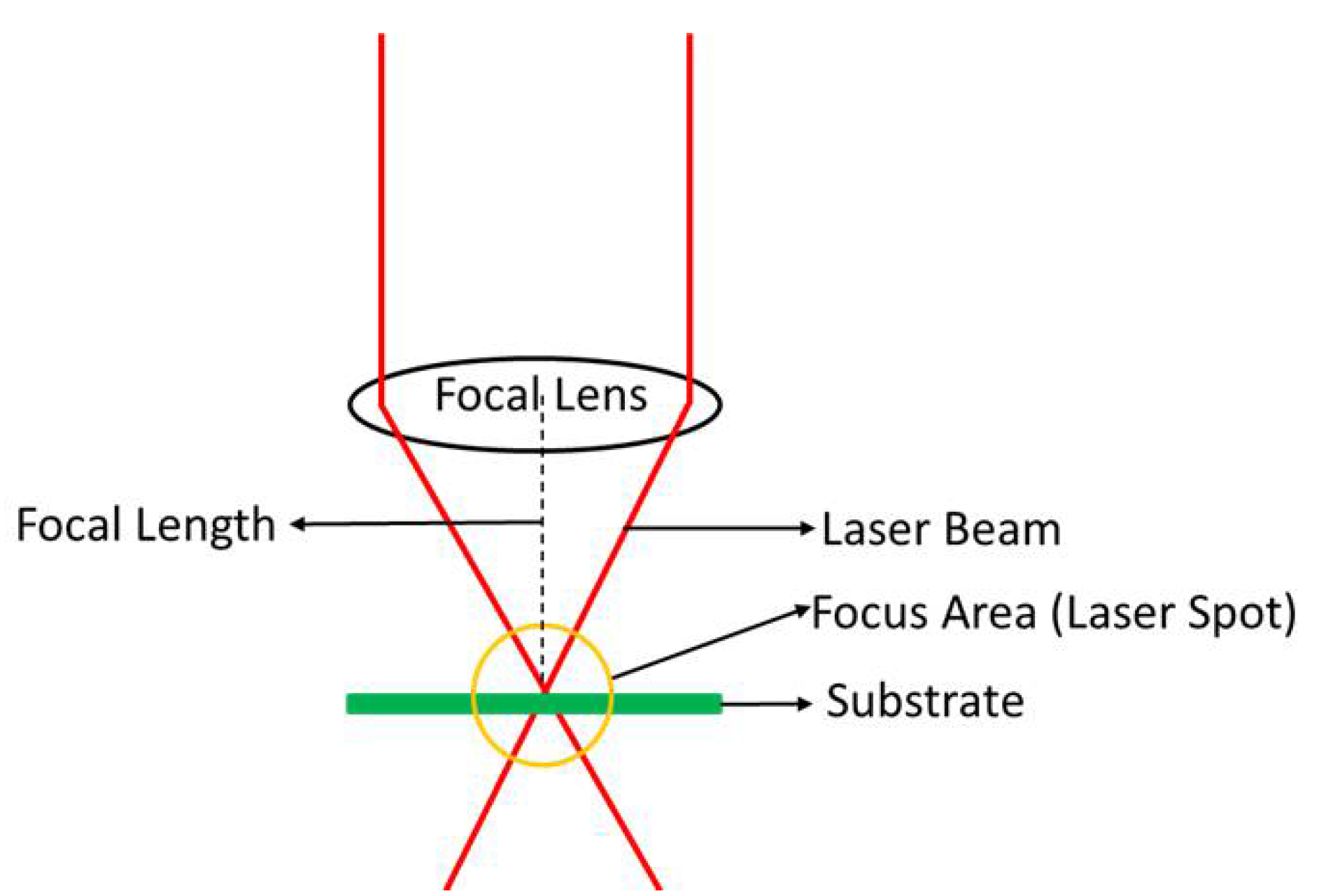
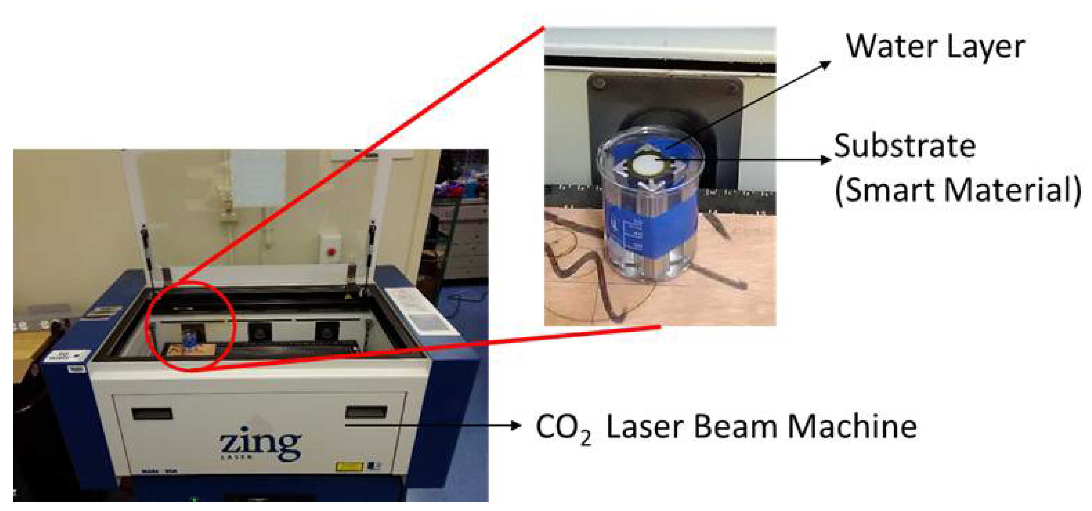
A state-of-the-art, digitally controlled, air-cooled CO2 Epilog Zing Laser 30 W machine, at 10.6 µm wavelength and using a continuous waveform, is employed in this study to perform both LBMM and LA-LBMM experiments. The laser power and scanning speed are computer-controlled, with increments of 1% up to 100%. A focusing lens focuses the laser beam at a distance of 38.1 mm from the machining surface. The laser beam used in this study has a spot size of 76 µm. Distilled water and ethylene glycol are used as the fluid medium in this study. While distilled water is selected because it is the most frequently used medium for the LA-LBMM process, the selection of ethylene glycol is based on its higher viscosity and density. The substrate is submerged in distilled water, and ethylene glycol with the liquid film thickness maintained at 1 mm as suggested in the literature [17,18]. The focal point of the laser spot is maintained at the top surface of the substrate material for machining both in the air and in the liquid medium, as shown in Figure 3. Three levels of laser power are examined in order to understand its effects on geometries of the micro-cavities machined and the corresponding heat affected zones. A set of experiments are performed to compare the sizes of both micro-cavity and heat-affected zone. The diameters are measured using a digital microscope (Make-OMAX, Magnification 2000×, Gyeonggi-do, South Korea). The substrate material used in this study is a Lead Zirconate Titanate (PZT) ceramic material disk with a thickness of 250 µm. A constant machining duration of 2 s is maintained for all the experiments. The machining is done in a circular path on the substrate surface. The experimental setup of LBMM both in the air and under liquid medium is shown in Figure 4. Table 1 shows the experimental conditions used for micromachining of smart ceramic material during the LA-LBMM process.
4. Results and Discussion
4.1. Results of Micromachining on Smart Ceramics during LBMM and LA-LBMM Process
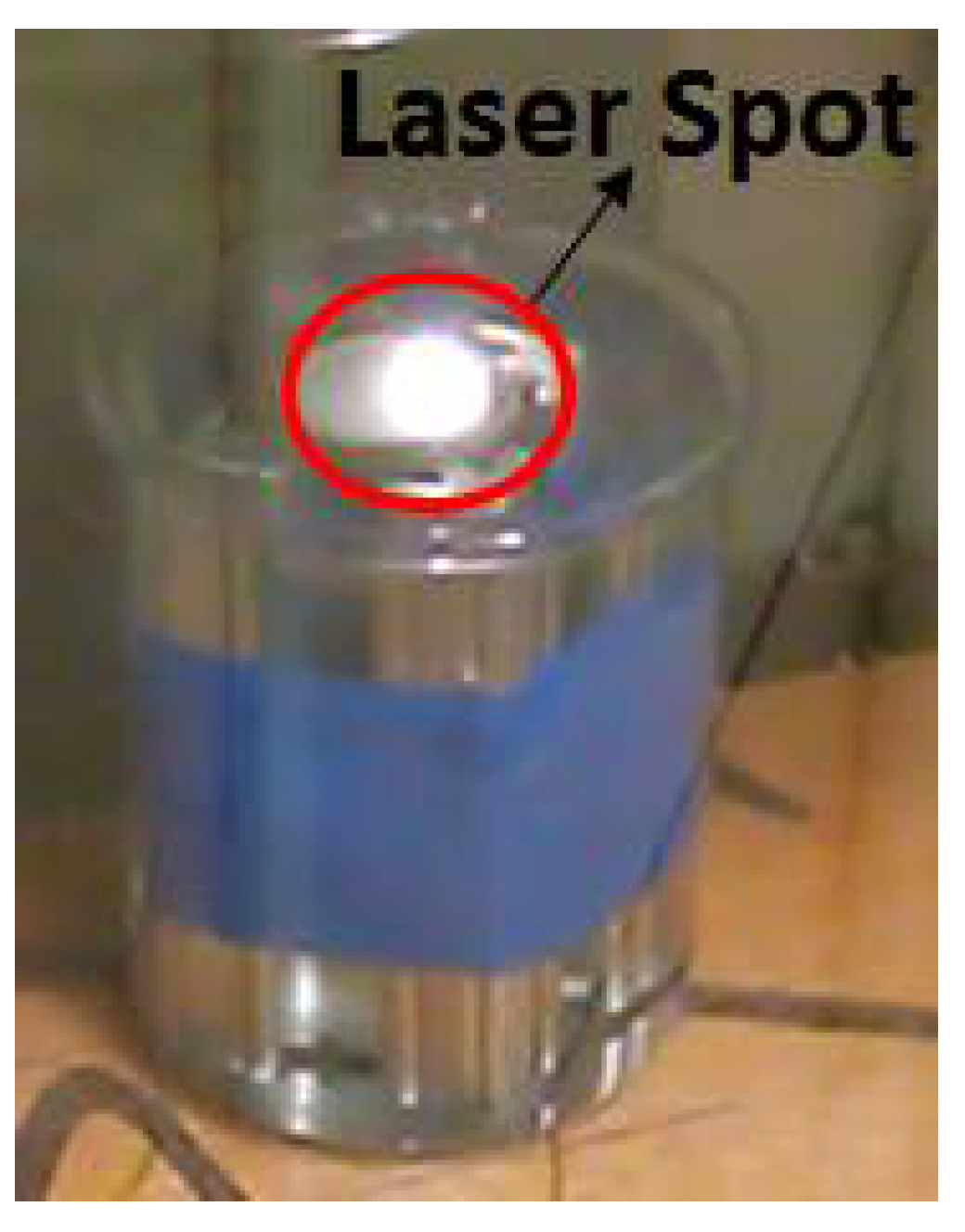
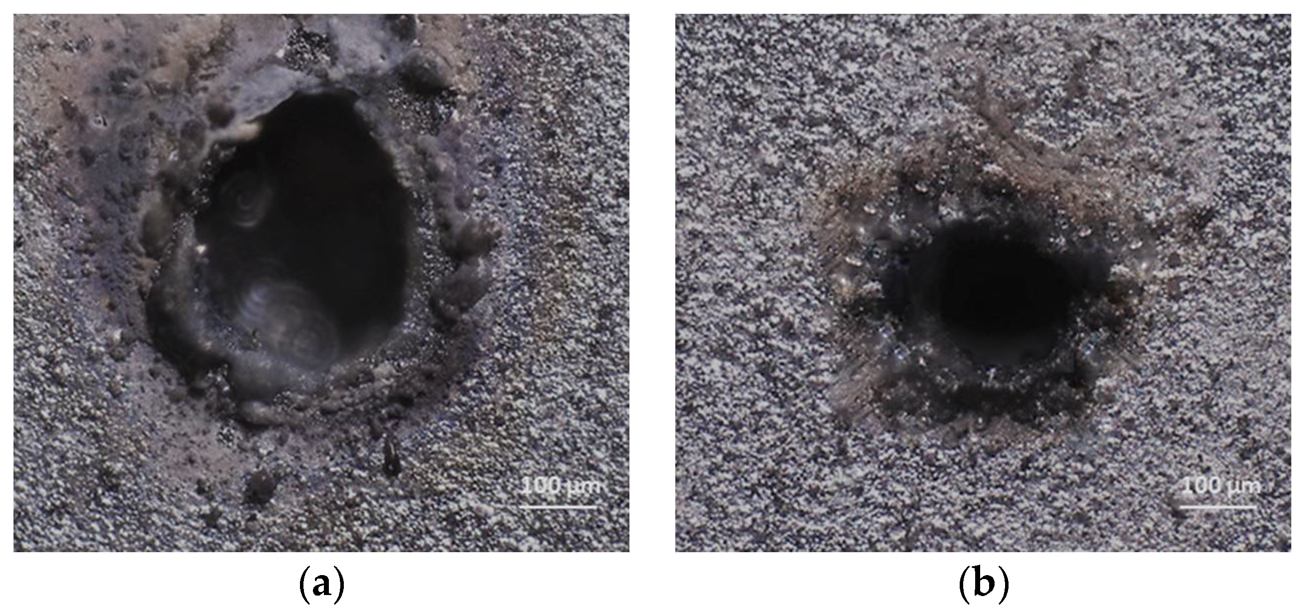
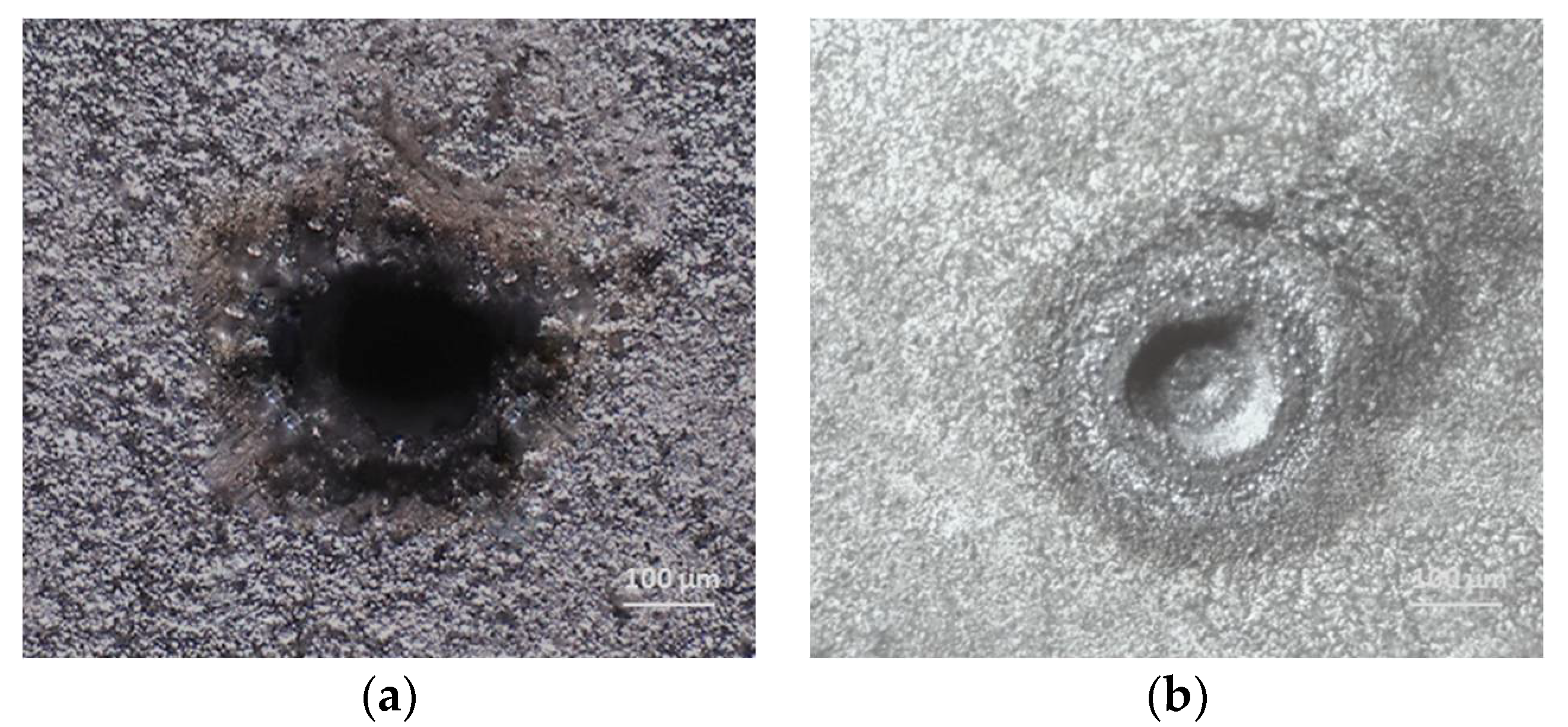
In this study, micro-cavities are successfully machined on PZT ceramic material using both LBMM and LA-LBMM processes. Figure 5 shows the irradiated laser spot on the PZT ceramic material during the LA-LBMM process. Optical images of representative micro-cavities machined on PZT ceramic during LBMM and LA-LBMM process under distilled water with a laser intensity of 10 W, laser spot size of 76 µm, and maintaining a constant traverse speed are shown in Figure 6. From the figure, it can be seen that the machining in air results in cavities with large diameters and large HAZ. Additionally, the machined surface shows material re-deposition and scorches due to the presence of temperature gradient and thermally induced stresses. The LA-LBMM process produced micro-cavities having less HAZ and reduced material deposition.
4.2. Effect of Laser Power on Cavity Size during LBMM and LA-LBMM Processes
Figure 7 shows the variation in cavity size with respect to different laser power for both LBMM and LA-LBMM process under distilled water. It is seen that the diameter of the cavities machined increases as the laser power is increased. Moreover, the cavity sizes in the LA-LBMM process were smaller than those in the air for corresponding laser intensities. There is a significant reduction in the cavity sizes when machined with power of 10 W and 30 W under liquid, when compared to air. The reduction in cavity diameters during liquid-assisted machining can be explained by the fact that the liquid medium absorbs the laser heat as it travels away from the machining zone. However, during the machining in air, the heat spreads to a larger distance resulting in larger cavity diameters. Machining under distilled water offered relatively sharp edges, a considerable reduction of scorches and machining debris. This can be explained considering the ability of the water to cool the molten debris fast causing it to solidify. The solidify debris does not re-deposit on the machining region resulting in a smoother surface. In the air medium, the molten material readily redeposits on the surface resulting in increased roughness.
4.3. Effect of Laser Power on HAZ Size during LBMM and LA-LBMM Processes
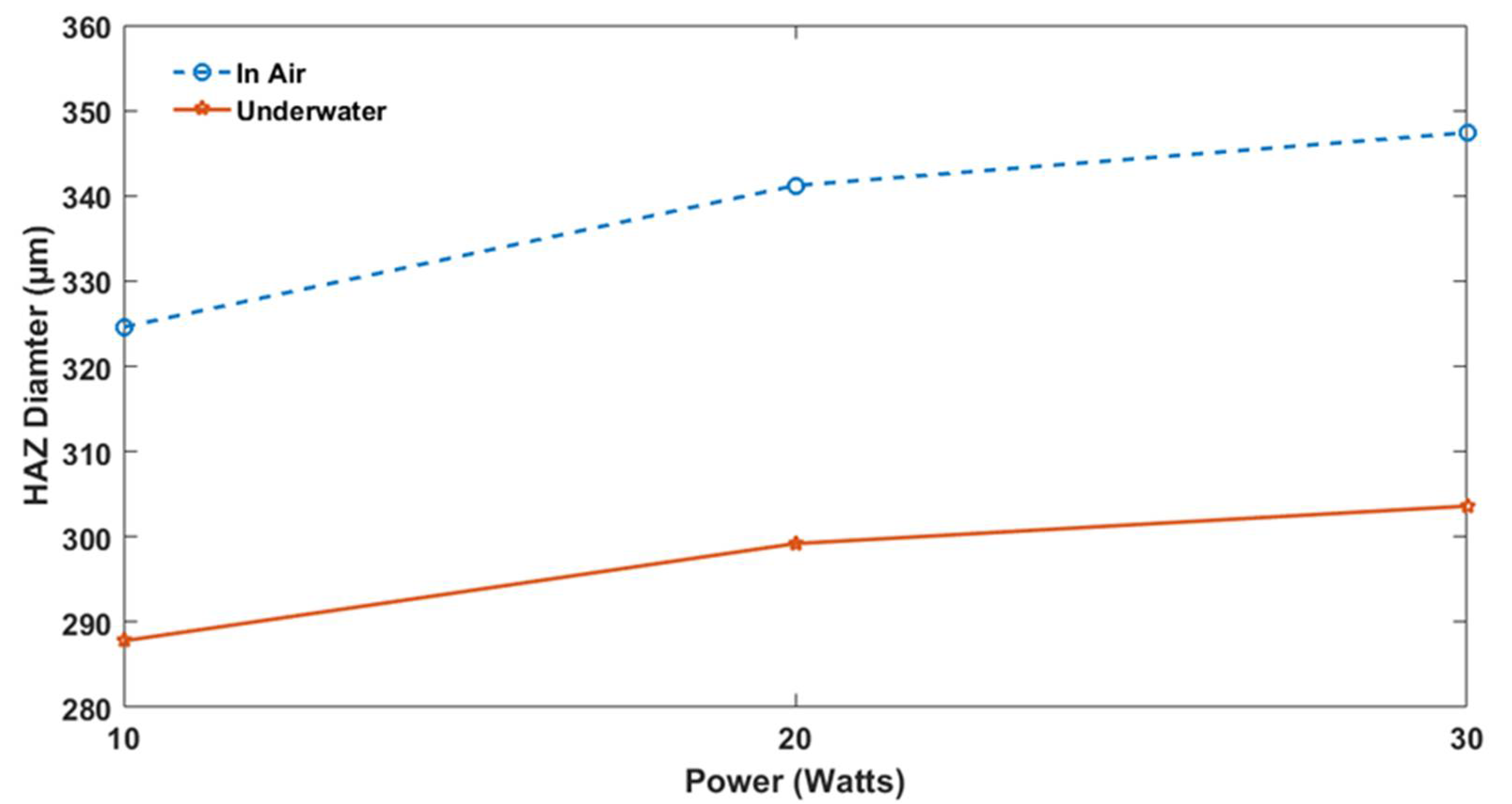
The HAZ is one of the significant limitations of laser beam micromachining process. Figure 8 shows the variation in the size of HAZ with respect to different laser power for both LBMM and LA-LBMM process under distilled water. The results suggest that the laser intensity has an adverse impact on the size of the HAZ. The size of HAZ increases with the increase in laser power. The scorch formation on the surface is a result of the high amount of heat energy accumulated for machining and can be attributed to the emission of fumes during the ablation process. The HAZ size and presence of scorches are significantly reduced during the LA-LBMM process compared to the LBMM process. The reduced scorches and HAZ are because of the cooling effect of the liquid molecules during the LA-LBMM process. The interaction of the liquid with the machined surface reduces the thermal stresses and temperature around the machined area to prevent thermal damage from occurring on the substrate surface thereby improving the quality of the micro-cavity.
4.4. Effect of Laser Power on Taper Angle during LBMM and LA-LBMM Process
The taper angle of the machined cavity during the LA-LBMM process is calculated using the equation
where tm is the substrate thickness, and Dtop and Dbot are the diameters at the entrance and exit of the cavity, respectively. Figure 9 shows the variation in taper angle with respect to laser power in the LBMM process and LA-LBMM process under distilled water. From the figure, it is understood that the power of the laser beam significantly influences taper angle of the machined cavity. As the power of the laser beam increases, the cavity diameters both at the top surface and at the bottom surface increases, which results in a reduction in taper angle. It is also observed that the taper angles of the machined cavities under liquid medium are lower than those in air. This can be attributed to the creation and collapse of bubbles in the liquid medium that are induced during laser beam micromachining [10]. The collapsing or bursting of bubbles in the laser beam machining zone in the liquid medium can form a micron level jet which impinges with the pressure of high shock towards the inside walls of the cavity. This ensures that the material is removed in uniform thickness from the inside of the cavities resulting in lesser taper angle.
4.5. Effect of Type of Liquid Medium during the LA-LBMM Process
Further experiments are conducted on PZT material with ethylene glycol as the liquid medium to understand the effect of different liquid medium on the quality of machining during the LA-LBMM process. Figure 10 shows the optical microscope images of micro-cavities machined using the LA-LBMM process under distilled water and ethylene glycol. It can be seen that the cavity size and the HAZ size are lower when the machining is performed under ethylene glycol compared with water. It is also observed that the depth of the cavity machined during LA-LBMM process under ethylene glycol is shallow compared to underwater machining. This can be attributed to the high viscosity and high density of ethylene glycol [8]. The viscosity of the ethylene glycol is almost 18 times higher than that of water, which prevents cavitation bubble formation resulting in reduced material removal. Moreover the density of ethylene glycol is almost 11 times that of water. The results suggest that higher viscosity and higher dense wetting medium tends to absorb higher laser power, causing lesser material removal.
4.6. Validation of Mathematical Model with Experimentation
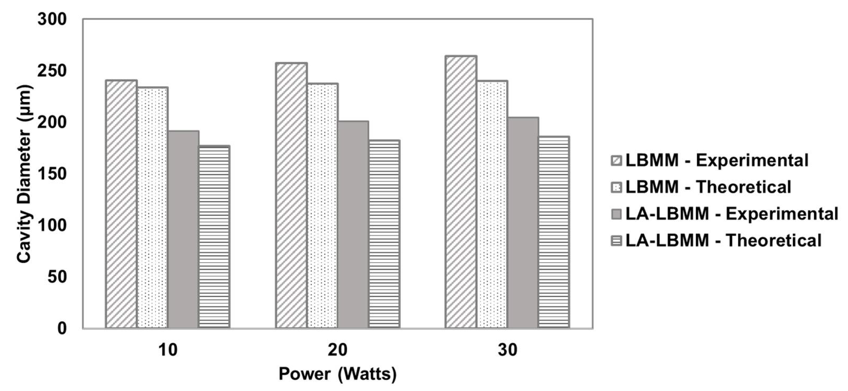
The predictive mathematical model developed in this study is validated through experimentation. The absorption coefficient αm of the PZT is taken as 1.48 [19]. The heat flux efficiency is assumed to be 0.9. The power density required for melting Icm is calculated to be 3830 W/cm2. The critical power density required for melting Ich is calculated to be 0.003 W/cm2. Figure 11 shows the comparison between cavity diameters of experimental and theoretical model predictions for LBMM and LA-LBMM processes. The comparison between HAZ diameters of experimental and analytical model predictions for LBMM and LA-LBMM processes is shown in Figure 12. It can be seen that the analytical model for both cavity diameter and HAZ diameter is capable of predicting the experimental results with an accuracy of 10% error.
5. Conclusions
In this study, micromachining of smart ceramic materials was successfully performed using the Liquid Assisted—Laser Beam Micromachining (LA-LBMM) process. The effect of laser power on the machining quality was studied. Additionally, the machining results of the LA-LBMM process were compared with those of the Laser Beam Micromachining (LBMM) process. An analytical model was developed to predict the cavity size and HAZ size during both LBMM and LA-LBMM processes. The significant findings of this study are as follows:
- The LA-LBMM process produces cavities with a smaller diameter and smaller HAZ compared to that of the LBMM process. The machined surface in the LA-LBMM process showed better surface quality along with limited material re-deposition and scorches compared to LBMM process.
- The laser power has a significant effect on the sizes of cavity and HAZ. The cavity size increases as the laser power is increased. The cavities produced through LA-LBMM process had smaller sizes compared to that of LBMM process.
- The analysis of HAZ size showed that the laser power adversely affected the machining quality. However, the HAZ size was significantly lower during the LA-LBMM process compared to the LBMM process.
- It is found that the LA-LBMM process is capable of minimizing the taper of the micro-cavities.
- The developed analytical model is capable of predicting the experimental results accurately, with an error of less than 10%.
- The experimental study done on the LA-LBMM process using different liquid media suggested that the machining in water medium produced more material removal compared to that of ethylene glycol.
- The mathematical model was developed for the prediction of HAZ diameter both in air and underwater conditions. The analytical results can well predict and are in accordance with the experimental diameter of HAZ both in air and underwater.
- This study can be used to enhance our knowledge on micromachining advanced engineering materials, including smart ceramics, composite materials, materials that are thermally sensitive and other materials whose microstructure changes due to the extremely high temperatures of the laser beam.
Author Contributions
S.J. and M.P. conceived and designed the experiments. M.P. performed the experiments and S.J. interpreted and analyzed the experimental data. M.P. developed the mathematical model and S.J. validated the model through experimentation. Both M.P. and S.J. prepared the manuscript together.
Acknowledgments
We would like to thank the College of Engineering and Computer Science at California State University Fullerton for providing facility for this research.
Conflicts of Interest
The authors declare no conflict of interest.
Nomenclature
| Diameter at the cavity exit (μm) | |
| Diameter at the cavity entrance (μm) | |
| Ich | Critical power density required for material recrystallization (W/cm2) |
| Icm | Critical power density required for melting material (W/cm2) |
| Laser intensity (W/cm2) | |
| Pa | Average power of the laser (W) |
| Average power of the laser in liquid (W) | |
| Radius of the machined cavity during LBMM (μm) | |
| Radius of the machined cavity during LA-LBMM (μm) | |
| Radius of HAZ during LBMM (μm) | |
| Radius of HAZ during LA-LBMM (μm) | |
| R | Laser spot radius (μm) |
| tm | Substrate material thickness (μm) |
| Absorption coefficient of the substrate material (cm−1) | |
| ρ | Density of substrate material (kg/mm3) |
| Heat flux efficiency | |
| Heat liberation rate at the melting of the substrate material (J/s) | |
| Heat liberation rate at recrystallization of the substrate material (J/s) | |
| θ | Taper angle (degree) |
References
- Eom, C.-B.; Trolier-McKinstry, S. Thin-Film Piezoelectric MEMS. MRS Bull. 2012, 37, 1007–1017. [Google Scholar] [CrossRef]
- Uppal, N.; Shiakolas, P.S.; Priya, S. Micromachining of PZT using ultrafast femtosecond laser. Ferroelectr. Lett. 2005, 32, 67–77. [Google Scholar] [CrossRef]
- Desbiens, J.-P.; Masson, P. ArF excimer laser micromachining of Pyrex, SiC and PZT for rapid prototyping of MEMS components. Sens. Actuators A Phys. 2007, 136, 554–563. [Google Scholar] [CrossRef]
- Mauclair, C.; Pietroy, D.; Maio, Y.D.; Baubeau, E.; Colombier, J.-P.; Stoian, R.; Pigeon, F. Ultrafast laser micro-cutting of stainless steel and PZT using a modulated line of multiple foci formed by spatial beam shaping. Opt. Lasers Eng. 2015, 67, 212–217. [Google Scholar] [CrossRef]
- Mistry, V.; James, S. Finite element analysis and simulation of liquid-assisted laser beam machining process. Int. J. Adv. Manuf. Technol. 2018, 94, 2325–2331. [Google Scholar] [CrossRef]
- Chung, C.K.; Lin, S.L. CO2 laser micromachined crackless through holes of Pyrex 7740 glass. Int. J. Mach. Tools Manuf. 2010, 50, 961–968. [Google Scholar] [CrossRef]
- Zeng, D.W.; Li, K.; Yung, K.C.; Chan, H.L.W.; Choy, C.L.; Xie, C.S. UV laser micromachining of piezoelectric ceramic using a pulsed Nd: YAG laser. Appl. Phys. A 2004, 78, 415–421. [Google Scholar] [CrossRef]
- Garcia-Giron, A.; Sola, D.; Peña, J. Liquid-assisted laser ablation of advanced ceramics and glass-ceramic materials. Appl. Surf. Sci. 2016, 363, 548–554. [Google Scholar] [CrossRef]
- López López, J.M.; Bakrania, A.; Coupland, J.; Marimuthu, S. Droplet assisted laser micromachining of hard ceramics. J. Eur. Ceram. Soc. 2016, 36, 2689–2694. [Google Scholar] [CrossRef] [Green Version]
- Charee, W.; Tangwarodomnukun, V.; Dumkum, C. Laser ablation of silicon in water under different flow rates. Int. J. Adv. Manuf. Technol. 2015, 78, 19–29. [Google Scholar] [CrossRef]
- Wee, L.M.; Ng, E.Y.K.; Prthama, A.H.; Zheng, H. Micro-machining of silicon wafer in air and under water. Opt. Laser Technol. 2011, 43, 62–71. [Google Scholar] [CrossRef]
- Yan, Y.; Li, L.; SEzer, K.; Wang, W.; Whitehead, D.; Ji, L.; Bao, Y.; Jiang, Y. CO2 laser underwater machining of deep cavities in alumina. J. Eur. Ceramic Soc. 2011, 31, 2793–2807. [Google Scholar] [CrossRef]
- Dong-Gyu, A.; Gwang-Won, J. Influence of process parameters on drilling characteristics of Al 1050 sheet with thickness of 0.2 mm using pulsed Nd: YAG laser. Trans. Nonferrous Met. Soc. China 2009, 19, s157–s163. [Google Scholar]
- Bharatish, A.; Narasimha Murth, H.N.; Anand, B.; madhusoodana, C.D.; Praveena, G.S.; Krishna, M. Characterization of hole circularity and heat affected zone in pulsed CO2 laser drilling of alumina ceramics. Opt. Laser Technol. 2013, 53, 22–32. [Google Scholar] [CrossRef]
- Darwish, S.; Ahmed, N.; Alahmari, A.M.; Mufti, N.A. A comparison of laser beam machining of micro-channels under dry and wet mediums. Int. J. Adv. Manuf. Technol. 2016, 83, 1539–1555. [Google Scholar] [CrossRef]
- Miraoui, I.; Boujelbene, M.; Zaied, M. High-Power Laser Cutting of Steel Plates: Heat Affected Zone Analysis. Adv. Mater. Sci. Eng. 2016, 2016. [Google Scholar] [CrossRef]
- Alahmari, A.M.; Ahmed, N.; Darwish, S. Laser beam micro-machining under water immersion. Int. J. Adv. Manuf. Technol. 2016, 83, 1671–1681. [Google Scholar] [CrossRef]
- Tangwarodomnukun, V.; Wang, J.; Mathew, P. A comparison of dry and underwater laser micromachining of silicon substrates. Key Eng. Mater. 2010. [Google Scholar] [CrossRef]
- Knite, M. Study of optical properties of PLZT ceramics by laser calorimetry. In 10th International School on Quantum Electronics: Lasers: Physics and Applications; SPIE: Varna, Bulgaria, 1999. [Google Scholar]
Figure 1.
Schematic of Laser Beam Micromachining Process (a) in air (b) Liquid-Assisted.

Figure 2.
Schematic of Gaussian beam profile used in LA-LBMM process.

Figure 3.
Schematic of laser focused on the top surface of the substrate both in LBMM and LA-LBMM processes.
Figure 3.
Schematic of laser focused on the top surface of the substrate both in LBMM and LA-LBMM processes.

Figure 4.
Experimental setup of LA-LBMM process for machining smart ceramic materials.

Figure 5.
Irradiated laser spot on the substrate surface during LA-LBMM process.

Figure 6.
Micromachined cavities in smart ceramic materials using (a) the LBMM process, and (b) the LA-LBMM process under Distilled Water.
Figure 6.
Micromachined cavities in smart ceramic materials using (a) the LBMM process, and (b) the LA-LBMM process under Distilled Water.

Figure 7.
Variation in cavity size with respect to laser power LBMM process and LA-LBMM process.
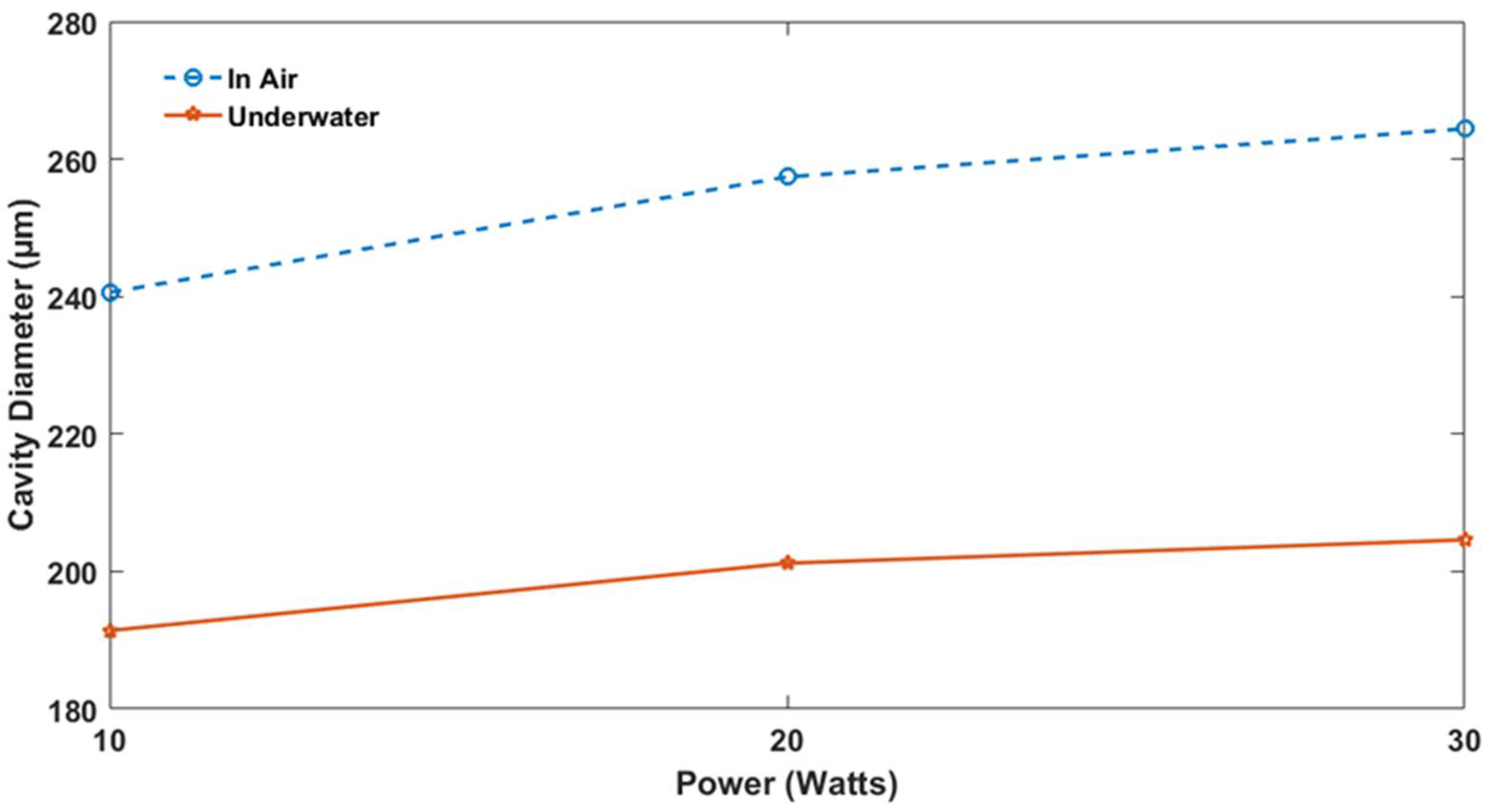
Figure 8.
Variation in HAZ size with respect to laser power in the LBMM process and the LA-LBMM process.
Figure 8.
Variation in HAZ size with respect to laser power in the LBMM process and the LA-LBMM process.

Figure 9.
Variation in taper angle with respect to laser power in the LBMM process and LA-LBMM process under distilled water.
Figure 9.
Variation in taper angle with respect to laser power in the LBMM process and LA-LBMM process under distilled water.

Figure 10.
Micromachined cavities in the smart material using the LA-LBMM process under (a) distilled water, and (b) ethylene glycol.
Figure 10.
Micromachined cavities in the smart material using the LA-LBMM process under (a) distilled water, and (b) ethylene glycol.

Figure 11.
Comparison between cavity diameters of experimental and theoretical model predictions for LBMM and LA-LBMM processes.
Figure 11.
Comparison between cavity diameters of experimental and theoretical model predictions for LBMM and LA-LBMM processes.

Figure 12.
Comparison between HAZ diameters of experimental and analytical model predictions for the LBMM and LA-LBMM processes.
Figure 12.
Comparison between HAZ diameters of experimental and analytical model predictions for the LBMM and LA-LBMM processes.


Table 1.
Experimental conditions used for micromachining smart ceramic materials using LA-LBMM process.
Table 1.
Experimental conditions used for micromachining smart ceramic materials using LA-LBMM process.
| Process Parameters | |
|---|---|
| Laser Source | CO2 Laser |
| Substrate | Lead Zirconate Titanate (PZT) |
| Substrate Thickness (μm) | 250 |
| Laser Wavelength (µm) | 10.6 |
| Laser Power (W) | 10, 20, 30 |
| Laser Spot Diameter (µm) | 76 |
| Focal Length (mm) | 38.1 |
| Machining Duration | 2 s |
| Liquid Medium | Distilled Water and Ethylene Glycol |
| Liquid film thickness (mm) | 1 |
© 2018 by the authors. Licensee MDPI, Basel, Switzerland. This article is an open access article distributed under the terms and conditions of the Creative Commons Attribution (CC BY) license (http://creativecommons.org/licenses/by/4.0/).
Share and Cite
MDPI and ACS Style
Parmar, M.; James, S. Experimental and Modeling Study of Liquid-Assisted—Laser Beam Micromachining of Smart Ceramic Materials. J. Manuf. Mater. Process. 2018, 2, 28. https://doi.org/10.3390/jmmp2020028
AMA Style
Parmar M, James S. Experimental and Modeling Study of Liquid-Assisted—Laser Beam Micromachining of Smart Ceramic Materials. Journal of Manufacturing and Materials Processing. 2018; 2(2):28. https://doi.org/10.3390/jmmp2020028
Chicago/Turabian StyleParmar, Mayur, and Sagil James. 2018. "Experimental and Modeling Study of Liquid-Assisted—Laser Beam Micromachining of Smart Ceramic Materials" Journal of Manufacturing and Materials Processing 2, no. 2: 28. https://doi.org/10.3390/jmmp2020028