Progressive Tool Wear in Cryogenic Machining: The Effect of Liquid Nitrogen and Carbon Dioxide

Department of Mechanical Engineering, Marmara University, 34722 Istanbul, Turkey
*
Author to whom correspondence should be addressed.
J. Manuf. Mater. Process. 2018, 2(2), 31; https://doi.org/10.3390/jmmp2020031
Submission received: 17 March 2018
/
Revised: 8 May 2018
/
Accepted: 11 May 2018
/
Published: 21 May 2018
(This article belongs to the Special Issue Precision Manufacturing)
Abstract
:This experimental study focuses on various cooling strategies and lubrication-assisted cooling strategies to improve machining performance in the turning process of AISI 4140 steel. Liquid nitrogen (LN2) and carbon dioxide (CO2) were used as cryogenic coolants, and their performances were compared with respect to progression of tool wear. Minimum quantity lubrication (MQL) was also used with carbon dioxide. Progression of wear, including flank and nose, are the main outputs examined during experimental study. This study illustrates that carbon dioxide-assisted cryogenic machining alone and with minimum quantity lubrication does not contribute to decreasing the progression of wear within selected cutting conditions. This study also showed that carbon dioxide-assisted cryogenic machining helps to increase chip breakability. Liquid nitrogen-assisted cryogenic machining results in a reduction of tool wear, including flank and nose wear, in the machining process of AISI 4140 steel material. It was also observed that in the machining process of this material at a cutting speed of 80 m/min, built-up edges occurred in both cryogenic cooling conditions. Additionally, chip flow damage occurs in particularly dry machining.
1. Introduction
In hard turning, high hardness of workpieces, large cutting forces, and high temperatures at the tool–workpiece interface impose extreme requirements for tool rigidity and tool wear resistance [1,2]. Under such conditions, various cutting tools, including CBN (cubic boron nitride), and polycrystalline cubic boron nitride (PCBN), have proven to be technologically viable tool materials [1]. However, the main concern with these tools is their cost and their economic viability [1]. On the other hand, it is possible to reduce the cost of the cutting tools used in the process by using a carbide cutting tool when machining hardened steel. High temperature in the machining process of such steel limits the usage of carbide cutting tools if effective cooling and/or lubrication are not implemented [1]. The conventional cooling approach is accepted as an effective way for most applications, but from an environmental standpoint, it is not always the way preferred by the machining community [3,4,5]. Therefore, dry machining [6] is used in the machining process of hardened steel [7]. Cryogenic machining seems to be promising as an alternative approach, considering the advantages associated with this approach [8]. In cryogenic machining applications, liquid nitrogen has frequently been used [8,9,10]. However, temperatures larger than 100 °K may be regarded by some researchers as cryogenics [8,11]. As LN2 can be stored in an insulated tank at very low temperature [11], it can be used for cooling during the machining processes. However, this might negatively influence the machine and equipment [12]. CO2 is able to be kept in pressurized tanks at a pressure of 57 bar in liquid form at room temperature [12]. An effective coolant is achieved at −78.5 °C because of phase transformation and the Joule-Thomson effect [11,13].
Many studies presented in the literature have reported the usage of liquid nitrogen as cryogenic coolant in the cutting process of different materials, such as IN718 [14,15,16], Ti-based alloys [17,18,19], composite materials [20], various materials [21], etc. There is an agreement in the majority of these studies that liquid nitrogen helps substantially to improve the machining performance of work materials. On the other hand, there have been few studies focusing on the effects of carbon dioxide on measured outputs in machining operations compared to liquid nitrogen. Al-Ghamdi et al. [13] reported that application of carbon dioxide snow improves the performance of steel and Ti-6Al-4V alloy. Carbon dioxide snow was also used in the grooving operation in the machining process of beta titanium alloy [22]. In the cutting operations of Ni-based alloy (IN 718) and Ti-based alloy (Ti-64), no substantial benefit was reported by the researchers as compared to other conventional coolant/lubricant [12]. The contribution of liquid nitrogen and carbon dioxide on machining performance have also been compared in the literature. The performance of these two coolants were compared, and it was reported that liquid nitrogen showed better performance than carbon dioxide with respect to the reduction of tool wear [23]. Jerold and Kumar [16] compared liquid nitrogen and carbon dioxide, taking into account machining performance in turning AISI 1045 work material, showing that liquid nitrogen and carbon dioxide reduced cutting temperature. Additionally, compared to wet and liquid nitrogen machining, carbon dioxide is much more helpful in reducing wear. Minimum quantity cooling lubrication has also been compared with dry machining in the literature by reporting that it has a considerable contribution to improving tool performance as compared with dry cutting in the machining of steel [24,25]. Review of the literature illustrates that LN2 has been widely used over the years in machining processes, but carbon dioxide is a relatively new approach for the machining community.
In this study, we aim to compare liquid nitrogen and carbon dioxide in terms of their contribution to reducing the progression of tool wear in the machining processes of AISI 4140 steel. This experimental study showed that compared to carbon dioxide, liquid nitrogen shows much more promising results by reducing tool wear notably. Delivering MQL simultaneously with carbon dioxide did not reduce tool wear. However, it should be noted that carbon dioxide generates much smaller chips.
2. Materials and Methods
In this study, AISI 4140 steel was used as work material. Round bar work materials were 50 mm in diameter and 80 mm long when cold rolled. Their hardness was 25 HRC. They were austenized at 815 °C, then quenched in oil and tempered in a salt bath at 580 °C for 1 h. After heat treatment, their hardness was measured as 42 HRC.
The turning tests were conducted on a Doosan CNC. CNMG 120408 M1 883 uncoated cutting tools were used in all machining experiments. A PTJNL2525M16JET tool holder was used. In cutting trials, the feed rate, f, depth of cut, d, and cutting speed, V, were kept constant at 0.2 mm/rev, 1.5 mm, 80 m/min, respectively. Tool wear was monitored by using digital optical microscopy. Progression of tool wear was monitored as a function of cutting distance. In each 100 mm machining, the test was interrupted and progression of tool wear was examined. Optris PI 400 was used for temperature measurement by using 0.66 emissivity. Emissivity was determined by using oven and thermocouple measurements.
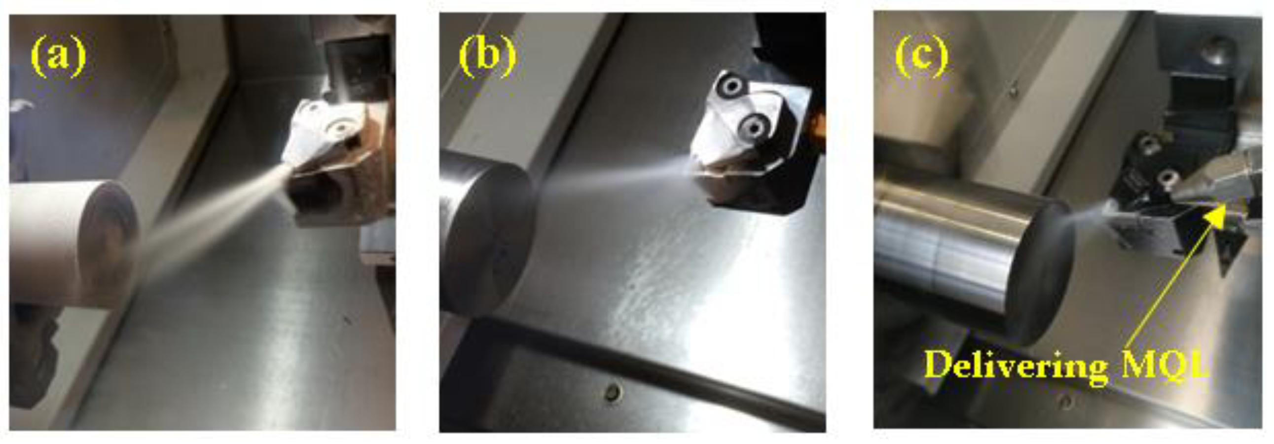
Machining experiments were conducted under dry and cryogenic machining. Cryogenic machining was conducted by delivering LN2 and CO2 through the tool holder, as depicted in Figure 1a,b. In case of CO2 + MQL, MQL was also simultaneously delivered through rake face of cutting tool, as illustrated in Figure 1c. For the MQL, CC22 Cutting oil HANGSTERFER’S lubricant was utilized at 43 mL/h and 5 Bar air pressure. The implementation of cooling strategies during the machining process is shown in Figure 1. Coolant was sent to the cutting region at 15 Bar pressure. The pressure of the carbon dioxide was 54 Bar.
3. Results and Discussion
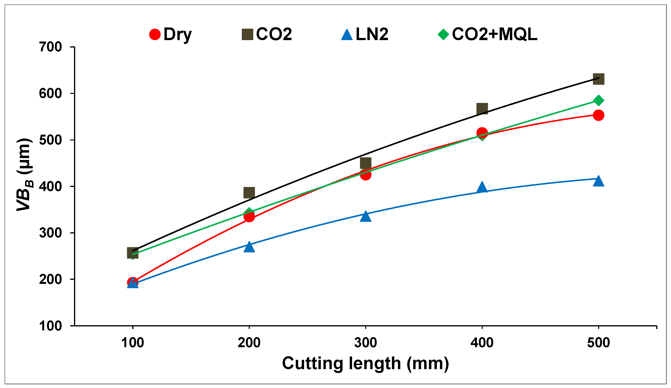
Flank wear is the first parameter considered when deciding whether the life of a cutting tool has reached its end. For this reason, in all studies related to wear, flank wear needs to be taken into account. This experimental work focuses on the effects of cutting conditions on progressive flank wear. Figure 2 shows the progression of flank wear in four different conditions, namely dry machining, carbon dioxide-assisted cryogenic machining, MQL and carbon dioxide-assisted machining, and liquid nitrogen-assisted cryogenic machining. The effect of the selected cutting conditions on progressive flank wear is apparent. It should be noted that as the cutting length is increased, the rate of flank wear increases too.
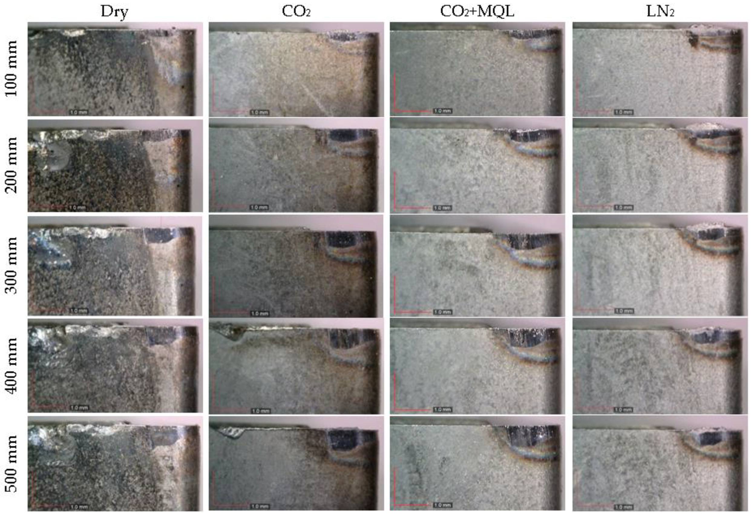
In carbon dioxide-assisted cryogenic machining process, the measured flank wear after 100 mm cutting length was 257 µm, and it was 631 µm after 500 mm cutting length, as shown in Figure 2. From these measured values, it can be concluded that among all three conditions, carbon dioxide-assisted cryogenic machining generates the largest flank wear rate. Delivering MQL with carbon dioxide did not help much in reducing flank wear. Measured flank wear after 100 mm cutting length in the dry machining process was approximately 190 µm, and it was approximately 550 µm after 500 mm cutting length. These values are much lower than the flank wear rate obtained from carbon dioxide-assisted cryogenic machining. The smallest flank wear rate was obtained from liquid nitrogen-assisted cryogenic machining, in which it was 412 µm after a 500 mm cutting length, as shown in Figure 2. Images of progressive flank wear under dry, carbon dioxide-assisted cryogenic machining, MQL and carbon dioxide-assisted cryogenic machining, and liquid nitrogen-assisted cryogenic machining are presented in Figure 3. The difference between liquid nitrogen-assisted machining and carbon dioxide-assisted machining is evident. It is a well-known fact that cryogenic temperatures prevents cutting tools to be soften, and consequently decreases wear rate; thus, the performance of the cutting tool under cryogenic cooling shows significant improvement. This argument can be supported from the literature, where it was reported that cryogenic cooling helps to reduce tool wear in the machining process of various work materials [26,27], as it reduces tool–chip interface temperature, thus preventing softening of the cutting tool [21].
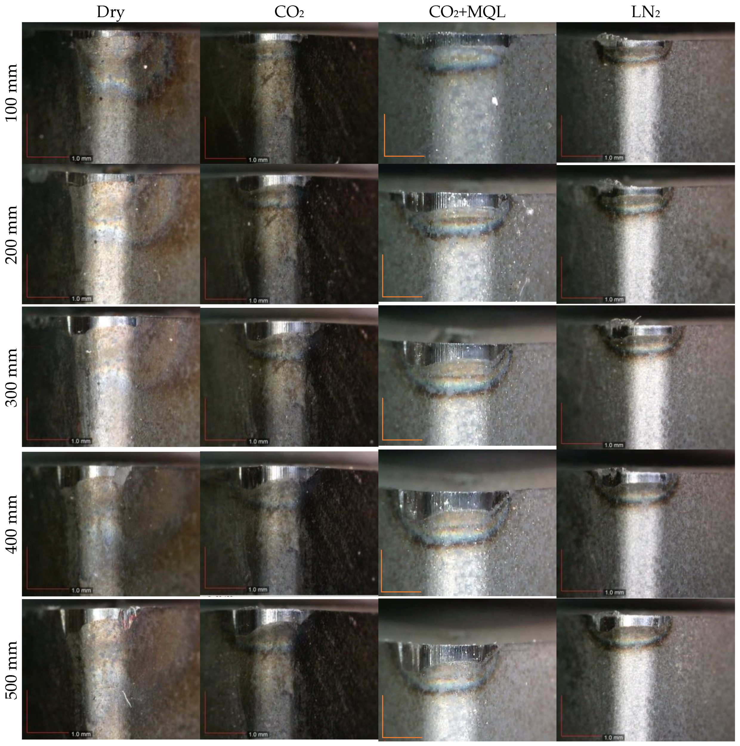
Although the temperature of carbon dioxide is much higher than liquid nitrogen, but also much lower than room temperature, the largest flank wear is observed in this condition, as it does not effectively penetrate the tool–chip interface [11]. The progressive nose wear resulting from the three different conditions is presented in Figure 4. The progression of nose wear shows a similar trend to the progression of flank wear presented in the previous section. As shown in Figure 4, the largest nose wear occurs for MQL and carbon dioxide-assisted cryogenic machining. These results are close to the results obtained for carbon dioxide-assisted cryogenic machining. After 500 mm cutting length, the measured nose wear was approximately 356 µm in the MQL and carbon dioxide-assisted cryogenic machining process. It was approximately 344 µm in the carbon dioxide-assisted cryogenic machining process, while it was approximately 310 µm and 280 µm in the dry and liquid nitrogen assisted cryogenic machining processes, respectively.
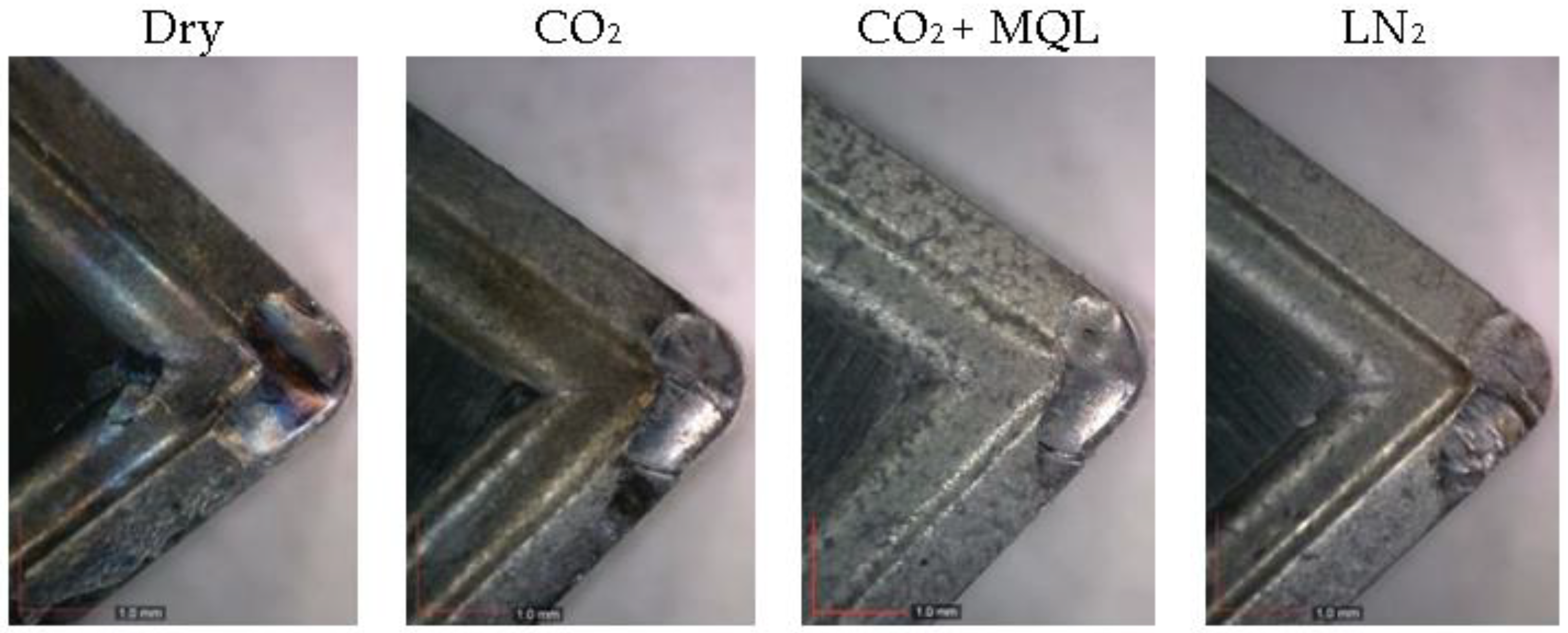
Compared to carbon dioxide-assisted cryogenic machining, liquid nitrogen-assisted cryogenic machining reduces the nose wear approximately seventeen percent. However, the interesting point of these results is again that the carbon dioxide-assisted cryogenic machining process results in much larger nose wear than that obtained from the dry machining process. MQL does not help to reduce nose wear. The clear difference between dry and MQL and carbon dioxide-assisted machining can be seen in Figure 5, which shows images of the progressive nose wear.
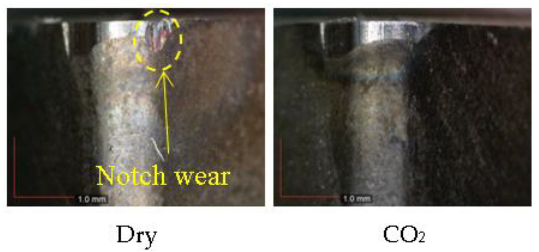
It should be noted that while dry machining leads to the occurrence of notch wear, no clear notch wear was observed in either the liquid nitrogen or carbon dioxide-assisted cryogenic machining processes. In the machining process of various materials, it was reported that cryogenic cooling, including CO2 and LN2, suppresses the occurrence of notch wear [11,26]. The notch wear in the dry machining process after 500 mm cutting length was approximately 530 µm. The notch wear observed on the insert utilized in dry machining can be seen in Figure 6. The crater wear resulting from the three different conditions after 500 mm cutting length is presented in Figure 7.
The area of crater wear resulting from dry machining was 1.43 mm2, it was approximately 1.28 mm2 for carbon dioxide-assisted cryogenic machining, it was approximately 1.13 mm2 for MQL and carbon dioxide-assisted cryogenic machining, and it was 1.21 mm2 for the liquid nitrogen-assisted cryogenic machining process.
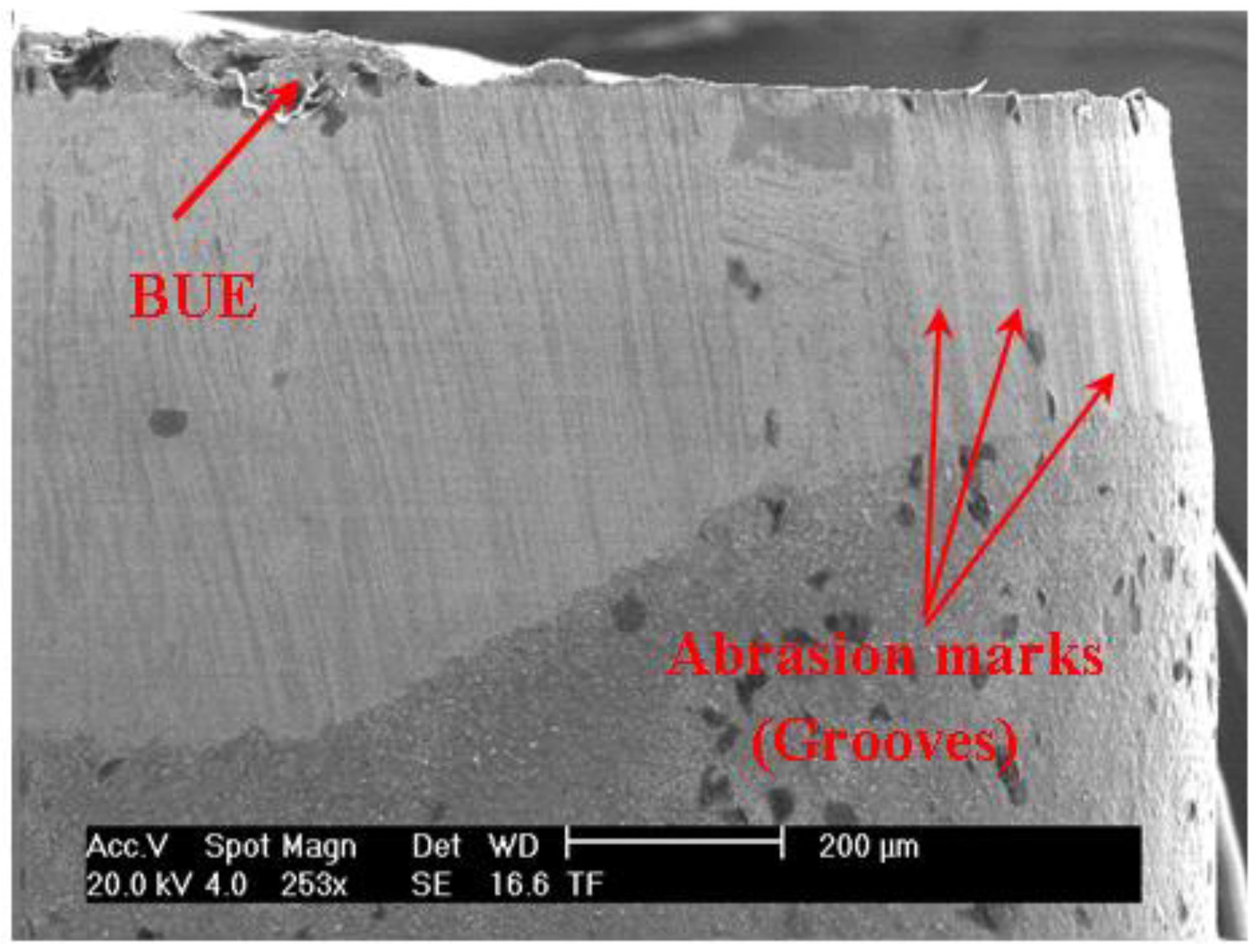
The experimental results presented in this study show an obvious difference between the liquid nitrogen and carbon dioxide-assisted machining processes in terms of progressive wear rate, particularly when flank wear and nose wear were taken into account. In cryogenic cooling conditions, the dominant wear mechanism observed was abrasive wear, as parallel grooves were observed through the flank surface. This wear mechanism is the most common one in the machining process of hard materials [28,29]. Additionally, diffusion wear dominates the progression of wear at the crater in all conditions, as depicted in Figure 7, and is also a typical wear mechanism when the temperature is high at the tool–chip interface during the machining of hard metals [30].
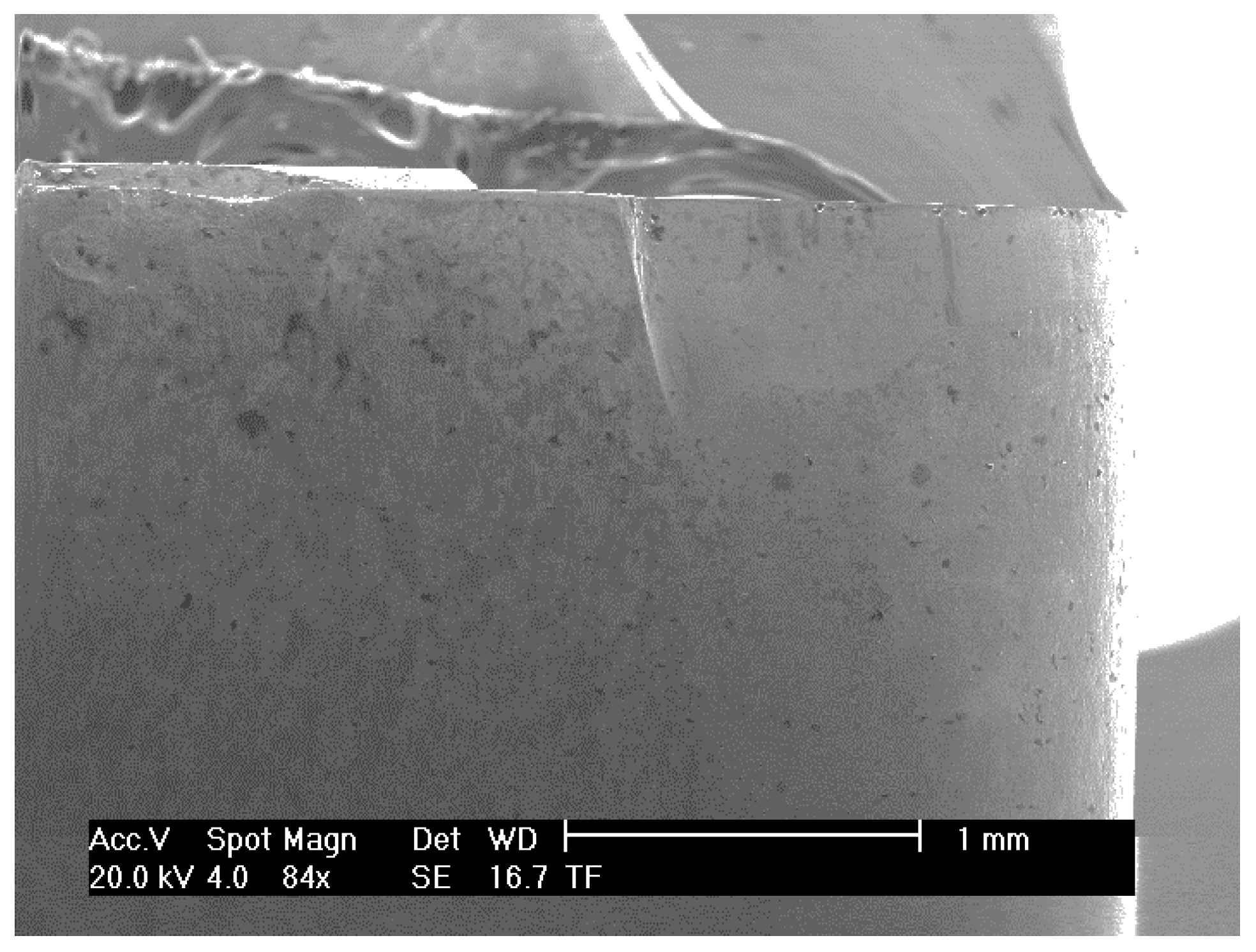
Built-up edge (BUE) is a common phenomenon observed in both cooling conditions. As shown in Figure 8, no built-up edge was observed in the dry machining process. However, Figure 9 shows that built-up edge occurred in carbon dioxide-assisted cryogenic machining after 500 mm cutting length. It is obvious from optical microscopy images that built-up edge occurred in liquid nitrogen-assisted cryogenic machining as well.
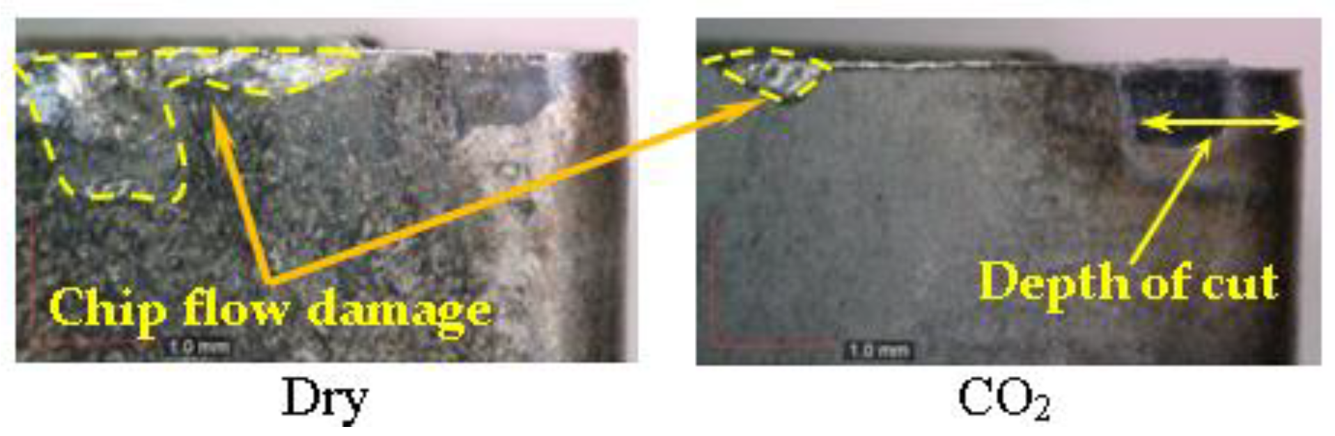
In addition to built-up edge, it is obvious that in the dry machining process, chip hammering (chip flow damage) occurs. In the carbon dioxide-assisted cryogenic machining process, chip hammering occurs after 300 mm cutting length. The chip flow damage that occurred after 500 mm cutting length in dry and carbon dioxide-assisted machining can be seen in Figure 10. Compared to carbon dioxide-assisted cryogenic machining, chip flow damage in dry machining is extremely large.
The chips generated during the machining process under given cutting conditions can be seen in Figure 11. While chips are not broken in dry and liquid nitrogen-assisted cryogenic machining, chips are broken in carbon dioxide-assisted cryogenic machining. MQL and carbon dioxide-assisted cryogenic machining also helps break the generated chips by producing similar chips as CO2 does. Chip flow damage is the result of continuous chips in dry machining; however, in carbon dioxide-assisted machining, chip flow direction should be the main reason for the occurrence of chip flow damage. Newly generated chips flow through the cutting edge. Chips hits and breaks cutting edge during flowing.
It should also be noted that although chips are broken under carbon dioxide-assisted machining, they are not broken under liquid nitrogen-assisted machining. The temperature of carbon dioxide is around −78 °C, while the temperature of liquid nitrogen is much lower than that. Considering this, the possible reason for broken chips in carbon dioxide-assisted cryogenic machining is the ductile-brittle transition temperature. The transition temperature of AISI 4140 is reported to be in between −40 and −20 °C [31]. During the carbon dioxide-assisted cryogenic machining process, the chips’ temperature might be close to this transition temperature range, and consequently, chips are broken. However, even this does not prevent chipping from occurring on the cutting edge of the insert.
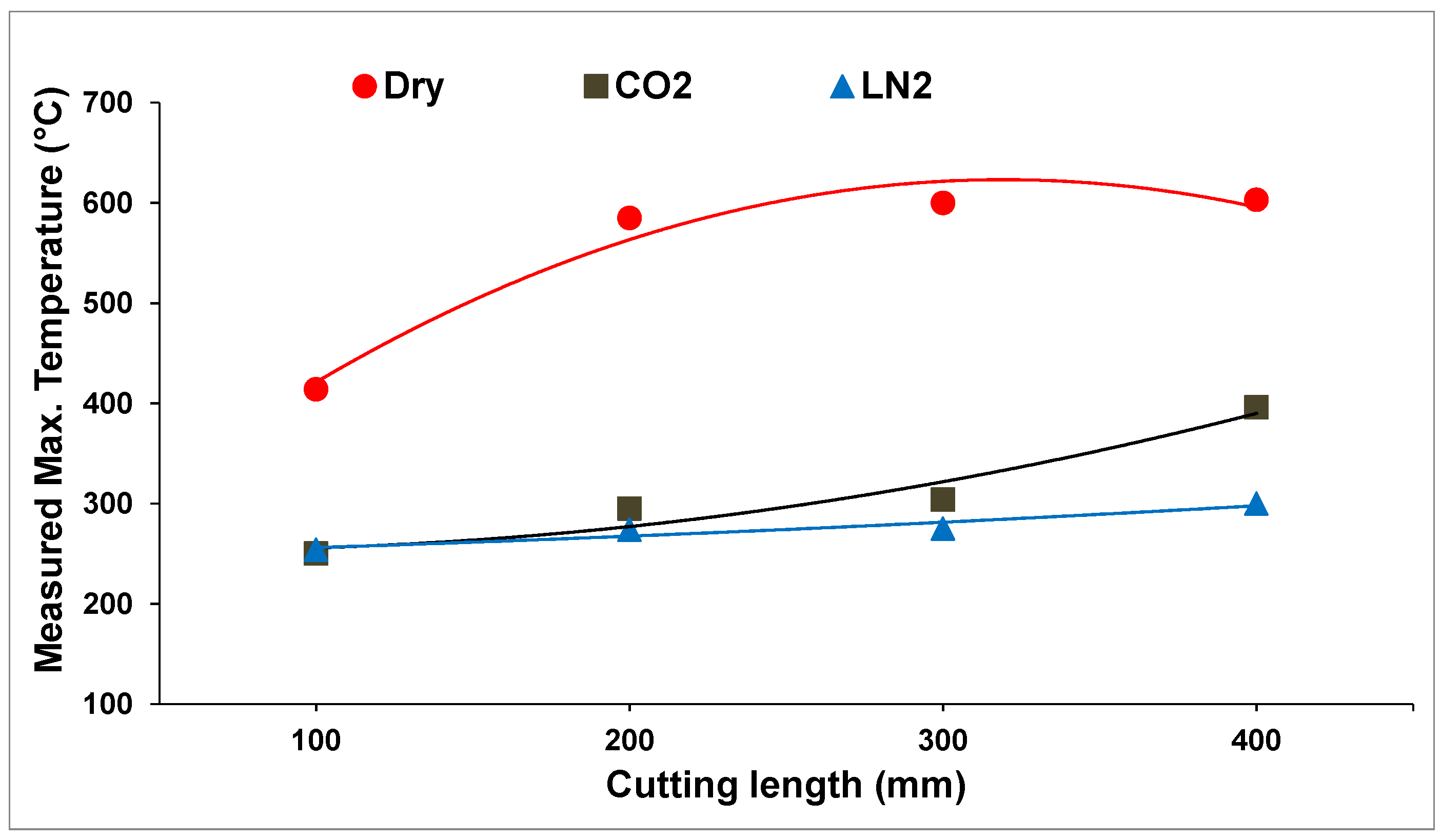
Figure 12 shows the measured maximum temperature during the machining process under three different conditions for the first 400 mm cutting length. These measured temperatures are not the temperature in between the chip and the cutting tool. It is the temperature of the newly generated chips during machining process. The difference between machining without any coolant and cryogenic cooling is obvious, but the difference between liquid nitrogen-assisted cryogenic machining and carbon dioxide-assisted cryogenic machining can be negligible. It should be noted that this temperatures show the maximum temperature of newly generated chips.
Although carbon dioxide-assisted machining has an evident cooling effect, it produces much larger flank and nose wear compared to dry machining in which wear is expected to be much larger due to the higher temperature. This is not an incidental result, as similar results were obtained when cutting speed was increased to 120 m/min [17]. This study confirms the repeatability of this result. However, in the metal cutting process of different materials, including titanium-based alloy, it has been reported that carbon dioxide-assisted machining improves tool life [18].
Wear is induced from the contact force, cutting length, and hardness of the softest material according to fundamental wear theory, as shown below [19]:
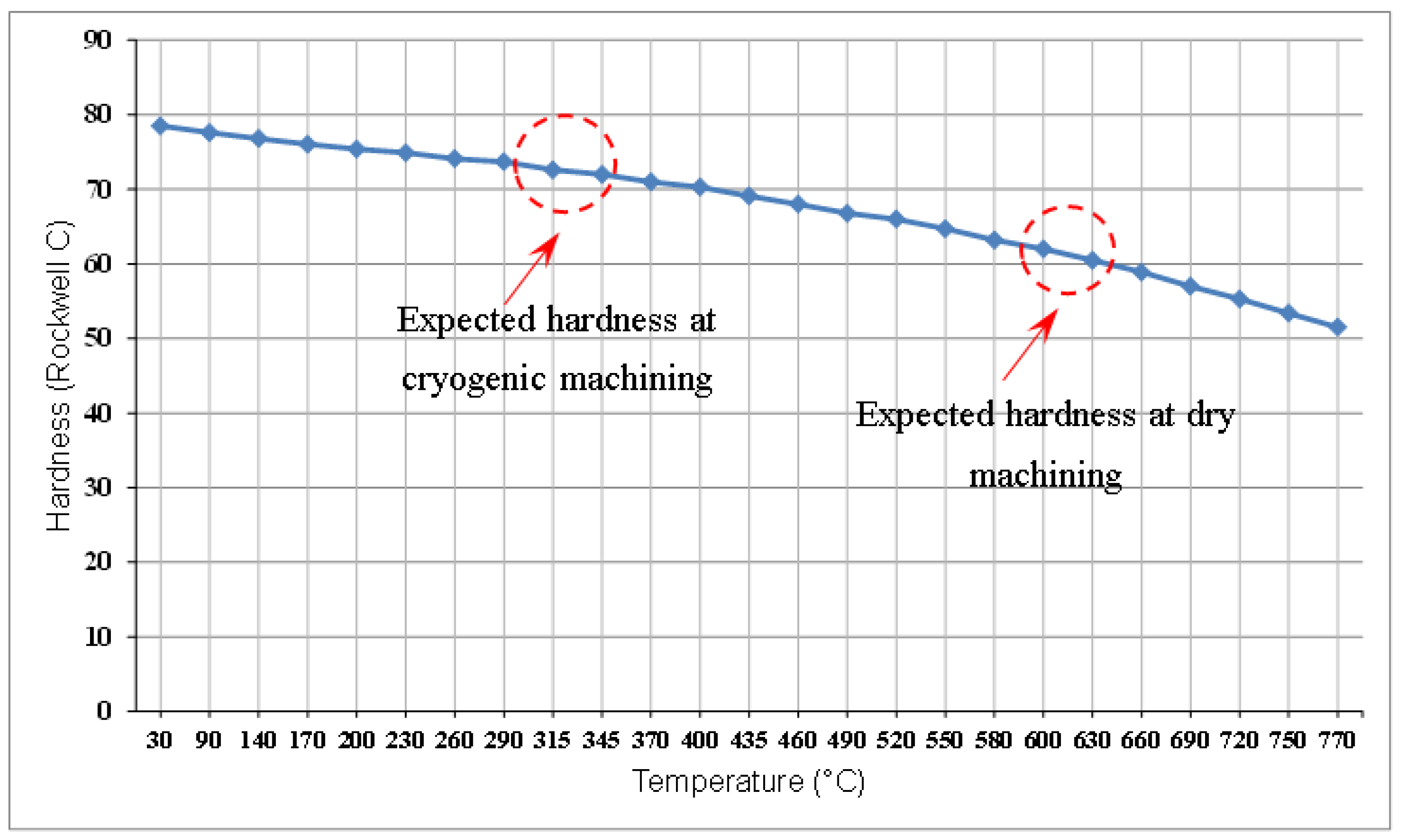
where W is the volumetric wear of the material, K is the Archard wear coefficient, F is the contact force, L is the cutting length, and H is the hardness of the cutting tool [19]. As the cutting length is the same in all of the machining tests conducted in this experiment, the only variables are contact force and the hardness of the cutting tool. There are two mechanisms occurring, here. One is the softening of the cutting tool due to the temperature occurring during cutting. For instance, the measured temperature is 600 °C in dry machining, but it is only 300 °C in cryogenic machining conditions (Figure 12), indicating that while the insert’s hardness is close to 75 HRC in cryogenic conditions, it is only around 63 HRC in dry cutting (Figure 13). However, since the temperature difference between LN2 and CO2 is negligible, no obvious hardness changes in the inserts used in both conditions are expected.
The second one is the contact force that is induced from the work material’s hardness. Although work material hardness is expected to increase with carbon dioxide-assisted machining, considering the cooling effect, its strength increases in liquid nitrogen-assisted cryogenic machining as well. From this perspective, lubrication effects might be effective parameters for determining the progression of wear in the machining process of AISI 4140 material. However, considering the obtained results from MQL and carbon dioxide-assisted machining, when cooling the cutting region with carbon dioxide, simultaneously delivering MQL does not help within these experimental conditions.
4. Conclusions
This experimental study presents the progression of tool wear in the turning process of AISI 4140 steel in carbon dioxide-assisted, MQL and carbon dioxide-assisted, and liquid nitrogen-assisted cryogenic machining, and presents a comparison of these results with the results obtained from the dry machining process with constant cutting parameters. This study shows that carbon dioxide-assisted cryogenic machining leads to the largest occurrence of wear, in comparison with dry and liquid nitrogen-assisted machining, with respect to the progression of flank wear and nose wear. Furthermore, when minimum quantity lubrication was delivered simultaneously with carbon dioxide, it resulted in much larger tool wear, including nose and flank, than dry machining did. It was also observed that in the machining process of this material at 80 m/min cutting speed, built-up edge takes place in both cryogenic cooling conditions. Among all four cutting conditions, chip flow damage only occurs in dry machining. Considering the current results, carbon dioxide-assisted machining is not recommended in machining AISI 4140 steel within the selected cutting parameters.
Author Contributions
Y.K. designed, supervised the experimental works, reviewing and editing the manuscript. A.G carried out the experimentations, plots the data and wrote the first draft of manuscript. Final version of manuscript was read and approved by the coauthors.
Acknowledgments
Authors would like to thanks to Emre Tascioglu from Marmara University for his assistance.
Conflicts of Interest
The authors declare no conflict of interest.
Nomenclature
| MQL | Minimum Quantity Lubrication |
| LN2 | Liquid Nitrogen |
| CO2 | Carbon dioxide |
| VBB | Flank wear |
| VBC | Nose wear |
| LN2 Rake & Flank | Applying LN2 from rake and flank face of cutting tool simultaneously |
| W | the volumetric wear of the material |
| K | the Archard wear coefficient |
| F | the contact force |
| L | the cutting length |
| H | the hardness of the softest material |
References
- More, A.S.; Jiang, W.; Brown, W.; Malshe, A.P. Tool wear and machining performance of cBN–TiN coated carbide inserts and PCBN compact inserts in turning AISI 4340 hardened steel. J. Mater. Process. Technol. 2006, 180, 253–262. [Google Scholar] [CrossRef]
- Rahman Rashid, R.; Sun, S.; Wang, G.; Dargusch, M. Machinability of a near beta titanium alloy. Proc. Inst. Mech. Eng. Part B J. Eng. Manuf. 2011, 225, 2151–2162. [Google Scholar] [CrossRef]
- Kaynak, Y.; Lu, T.; Jawahir, I. Cryogenic machining-induced surface integrity: A review and comparison with dry, MQL, and flood-cooled machining. Mach. Sci. Technol. 2014, 18, 149–198. [Google Scholar] [CrossRef]
- Ahmed, L.S.; Govindaraju, N.; Pradeep Kumar, M. Experimental investigations on cryogenic cooling in the drilling of titanium alloy. Mater. Manuf. Process. 2016, 31, 603–607. [Google Scholar] [CrossRef]
- Mia, M.; Dhar, N.R. Prediction of surface roughness in hard turning under high pressure coolant using Artificial Neural Network. Measurement 2016, 92, 464–474. [Google Scholar] [CrossRef]
- Krolczyk, G.; Nieslony, P.; Maruda, R.; Wojciechowski, S. Dry cutting effect in turning of a duplex stainless steel as a key factor in clean production. J. Clean. Prod. 2017, 142, 3343–3354. [Google Scholar] [CrossRef]
- Mia, M.; Dhar, N.R. Optimization of surface roughness and cutting temperature in high-pressure coolant-assisted hard turning using Taguchi method. Int. J. Adv. Manuf. Technol. 2017, 88, 739–753. [Google Scholar] [CrossRef]
- Shokrani, A.; Dhokia, V.; Munoz-Escalona, P.; Newman, S. State-of-the-art cryogenic machining and processing. Int. J. Comput. Integr. Manuf. 2013, 26, 616–648. [Google Scholar] [CrossRef] [Green Version]
- Mia, M.; Dhar, N.R. Influence of single and dual cryogenic jets on machinability characteristics in turning of Ti-6Al-4V. Proc. Inst. Mech. Eng. Part B J. Eng. Manuf. 2017. [Google Scholar] [CrossRef]
- Pervaiz, S.; Deiab, I.; Rashid, A.; Nicolescu, M. Minimal quantity cooling lubrication in turning of Ti6Al4V: Influence on surface roughness, cutting force and tool wear. Proc. Inst. Mech. Eng. Part B J. Eng. Manuf. 2017, 231, 1542–1558. [Google Scholar] [CrossRef]
- Machai, C.; Biermann, D. Machining of β-titanium-alloy Ti–10V–2Fe–3Al under cryogenic conditions: Cooling with carbon dioxide snow. J. Mater. Process. Technol. 2011, 211, 1175–1183. [Google Scholar] [CrossRef]
- Busch, K.; Hochmuth, C.; Pause, B.; Stoll, A.; Wertheim, R. Investigation of Cooling and Lubrication Strategies for Machining High-temperature Alloys. Proced. CIRP 2016, 41, 835–840. [Google Scholar] [CrossRef]
- Sorbo, N.W.; Dionne, J.J. Dry Drilling of Stackup Composite: Benefits of CO2 Cooling. SAE Int. J. Aerosp. 2014, 7, 156–163. [Google Scholar] [CrossRef]
- Kaynak, Y. Evaluation of machining performance in cryogenic machining of Inconel 718 and comparison with dry and MQL machining. Int. J. Adv. Manuf. Technol. 2014, 72, 919–933. [Google Scholar] [CrossRef]
- Courbon, C.; Pusavec, F.; Dumont, F.; Rech, J.; Kopac, J. Influence of Cryogenic Lubrication on the Tribological Properties of Ti6Al4V and Inconel 718 Alloys under Extreme Contact Conditions. Lubr. Sci. 2014, 26, 315–326. [Google Scholar] [CrossRef]
- Pusavec, F.; Deshpande, A.; Yang, S.; M’Saoubi, R.; Kopac, J.; Dillon, O.W.; Jawahir, I.S. Sustainable machining of high temperature Nickel alloy–Inconel 718: Part 2—Chip breakability and optimization. J. Clean. Prod. 2015, 87, 941–952. [Google Scholar] [CrossRef]
- Bermingham, M.; Kirsch, J.; Sun, S.; Palanisamy, S.; Dargusch, M. New observations on tool life, cutting forces and chip morphology in cryogenic machining Ti-6Al-4V. Int. J. Mach. Tools Manuf. 2011, 51, 500–511. [Google Scholar] [CrossRef]
- Courbon, C.; Pusavec, F.; Dumont, F.; Rech, J.; Kopac, J. Tribological behaviour of Ti6Al4V and Inconel718 under dry and cryogenic conditions—Application to the context of machining with carbide tools. Tribol. Int. 2013, 66, 72–82. [Google Scholar] [CrossRef]
- Al-Ghamdi, K.A.; Iqbal, A.; Hussain, G. Machinability comparison of AISI 4340 and Ti-6Al-4V under cryogenic and hybrid cooling environments: A knowledge engineering approach. Proc. Inst. Mech. Eng. Part B J. Eng. Manuf. 2015, 229, 2144–2164. [Google Scholar] [CrossRef]
- Josyula, S.K.; Narala, S.K.R. Machinability enhancement of stir cast Al-TiCp composites under cryogenic condition. Mater. Manuf. Process. 2017, 15, 1764–1774. [Google Scholar] [CrossRef]
- Dhar, N.; Paul, S.; Chattopadhyay, A. The influence of cryogenic cooling on tool wear, dimensional accuracy and surface finish in turning AISI 1040 and E4340C steels. Wear 2001, 249, 932–942. [Google Scholar] [CrossRef]
- Machai, C.; Iqbal, A.; Biermann, D.; Upmeier, T.; Schumann, S. On the effects of cutting speed and cooling methodologies in grooving operation of various tempers of β-titanium alloy. J. Mater. Process. Technol. 2013, 213, 1027–1037. [Google Scholar] [CrossRef]
- Klocke, F.; Krämer, A.; Sangermann, H.; Lung, D. Thermo-mechanical tool load during high performance cutting of hard-to-cut materials. Proced. CIRP 2012, 1, 295–300. [Google Scholar] [CrossRef]
- Maruda, R.W.; Krolczyk, G.M.; Feldshtein, E.; Nieslony, P.; Tyliszczak, B.; Pusavec, F. Tool wear characterizations in finish turning of AISI 1045 carbon steel for MQCL conditions. Wear 2017, 372, 54–67. [Google Scholar] [CrossRef]
- Krolczyk, G.; Maruda, R.; Nieslony, P.; Wieczorowski, M. Surface morphology analysis of duplex stainless steel (DSS) in clean production using the power spectral density. Measurement 2016, 94, 464–470. [Google Scholar] [CrossRef]
- Kaynak, Y.; Karaca, H.E.; Noebe, R.D.; Jawahir, I.S. Tool-wear analysis in cryogenic machining of NiTi shape memory alloys: A comparison of tool-wear performance with dry and MQL machining. Wear 2013, 306, 51–63. [Google Scholar] [CrossRef]
- Dhar, N.; Paul, S.; Chattopadhyay, A. Machining of AISI 4140 steel under cryogenic cooling—Tool wear, surface roughness and dimensional deviation. J. Mater. Process. Technol. 2002, 123, 483–489. [Google Scholar] [CrossRef]
- Dosbaeva, G.; El Hakim, M.; Shalaby, M.; Krzanowski, J.; Veldhuis, S. Cutting temperature effect on PCBN and CVD coated carbide tools in hard turning of D2 tool steel. Int. J. Refract. Met. Hard Mater. 2015, 50, 1–8. [Google Scholar] [CrossRef]
- Rashid, R.R.; Palanisamy, S.; Sun, S.; Dargusch, M. Tool wear mechanisms involved in crater formation on uncoated carbide tool when machining Ti6Al4V alloy. Int. J. Adv. Manuf. Technol. 2016, 83, 1457–1465. [Google Scholar] [CrossRef]
- Rashid, R.R.; Palanisamy, S.; Sun, S.; Dargusch, M. A case-study on the mechanism of flank wear during laser-assisted machining of a titanium alloy. Int. J. Mach. Mach. Mater. 2017, 19, 538–553. [Google Scholar] [CrossRef]
- Identification of Ductile to Brittle Transition Temperature by Using Plane Strain Specimen in Tensile Test and Correlation with Instrumented Charpy Impact Test: Experimental and Numerical Study. Available online: https://cfm2017.sciencesconf.org/129758/document (accessed on 17 March 2018).
- Groover, M.P. Fundamentals of Modern Manufacturing: Materials Processes, and Systems; John Wiley & Sons: New York, NY, USA, 2007. [Google Scholar]
Figure 1.
Experimental setup (a) delivering LN2; (b) CO2 from the rake and flank faces; (c) CO2 from the rake and flank faces and MQL from the rake face.
Figure 1.
Experimental setup (a) delivering LN2; (b) CO2 from the rake and flank faces; (c) CO2 from the rake and flank faces and MQL from the rake face.

Figure 2.
Progression of flank wear as a function of various conditions.

Figure 3.
Images of progressive flank wear under various machining conditions.

Figure 4.
Progression of nose wear as a function of various machining conditions.

Figure 5.
Images of progressive nose wear under various machining conditions.

Figure 6.
Images of notch wear occurring after 500 mm cutting length.

Figure 7.
Images of crater wear occurring after 500 mm cutting length.

Figure 8.
SEM images of the insert utilized in dry cutting.

Figure 9.
SEM images of the insert utilized in carbon dioxide-assisted cryogenic machining.

Figure 10.
Images of the chip flow damage occurring after 500 mm cutting length.

Figure 11.
Images of generated chips under dry, carbon dioxide (CO2), CO2+MQL, and liquid nitrogen (LN2)-assisted machining conditions.
Figure 11.
Images of generated chips under dry, carbon dioxide (CO2), CO2+MQL, and liquid nitrogen (LN2)-assisted machining conditions.
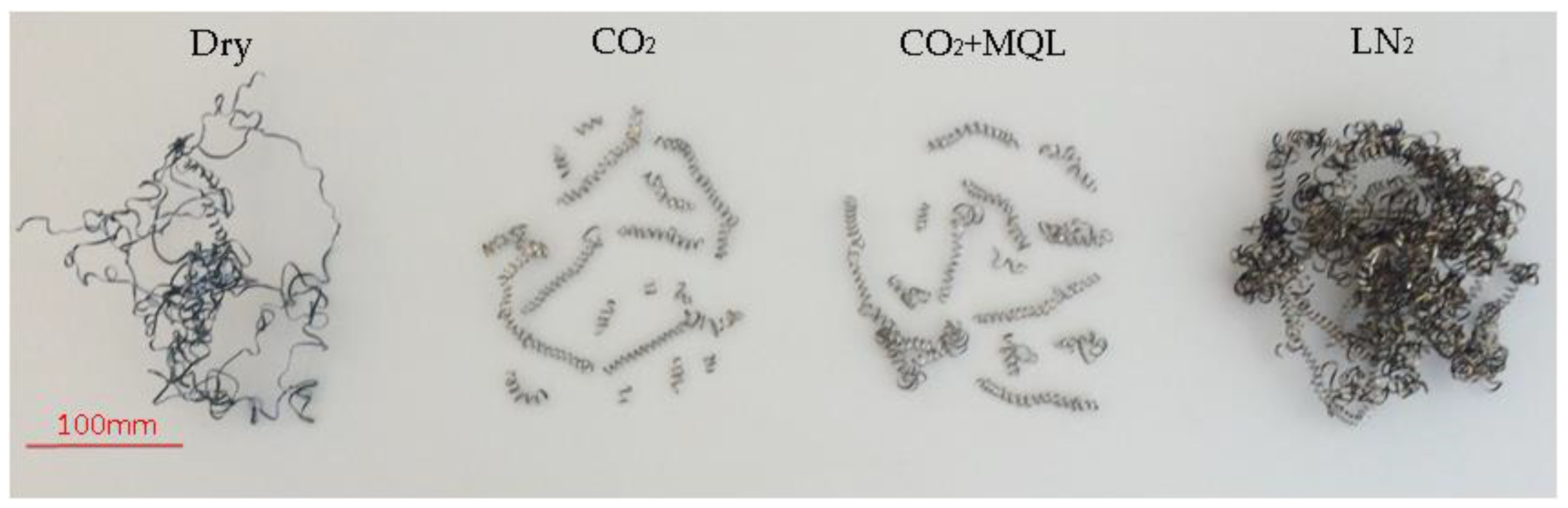
Figure 12.
Measured maximum temperature during machining processes under various conditions.

Figure 13.
Temperature vs hardness relationship for tungsten carbide cutting tool, adapted from Groover [32].
Figure 13.
Temperature vs hardness relationship for tungsten carbide cutting tool, adapted from Groover [32].

© 2018 by the authors. Licensee MDPI, Basel, Switzerland. This article is an open access article distributed under the terms and conditions of the Creative Commons Attribution (CC BY) license (http://creativecommons.org/licenses/by/4.0/).
Share and Cite
MDPI and ACS Style
Kaynak, Y.; Gharibi, A. Progressive Tool Wear in Cryogenic Machining: The Effect of Liquid Nitrogen and Carbon Dioxide. J. Manuf. Mater. Process. 2018, 2, 31. https://doi.org/10.3390/jmmp2020031
AMA Style
Kaynak Y, Gharibi A. Progressive Tool Wear in Cryogenic Machining: The Effect of Liquid Nitrogen and Carbon Dioxide. Journal of Manufacturing and Materials Processing. 2018; 2(2):31. https://doi.org/10.3390/jmmp2020031
Chicago/Turabian StyleKaynak, Yusuf, and Armin Gharibi. 2018. "Progressive Tool Wear in Cryogenic Machining: The Effect of Liquid Nitrogen and Carbon Dioxide" Journal of Manufacturing and Materials Processing 2, no. 2: 31. https://doi.org/10.3390/jmmp2020031