Article

Process Forces Analysis and a New Feed Control Strategy for Drilling of Unidirectional Carbon Fiber Reinforced Plastics (UD-CFRP)

1
Institute for Machine Tools and Production Processes, Chemnitz University of Technology, 09111 Chemnitz, Germany
2
Fraunhofer Institute for Machine Tools and Forming Technology, 09126 Chemnitz, Germany
*
Author to whom correspondence should be addressed.
J. Manuf. Mater. Process. 2018, 2(3), 46; https://doi.org/10.3390/jmmp2030046
Submission received: 17 May 2018 / Revised: 10 July 2018 / Accepted: 11 July 2018 / Published: 13 July 2018
(This article belongs to the Special Issue New Findings and Approaches in Machining Processes)

Abstract

:
Reliable machining of carbon fiber-reinforced plastics (CFRP) is the key for application of these lightweight materials. Due to its anisotropy, CFRP is a very difficult material to machine because of occurring delamination and fiber-pullouts. The tool design is especially crucial to minimize and to avoid these processing errors. In this paper a process analysis for drilling is shown for better understanding of the chip formation. Drilling of unidirectional CFRP enables the investigation of the effect of fiber orientation on the chip formation process. In theory, the amount of cut fibers and the cutting angle to the main cutting edge determine the cutting force. Experimental tests with varied macroscopic drill geometries verify this theory. Based on these detected relationships, the tool loads can be calculated for a successful tool design.

1. Introduction and State of the Art

The implementation of consistent lightweight construction leads to an increased use of composite materials in the automotive industry. Carbon fiber-reinforced plastic (CFRP) in particular is often used for its good strength-to-weight ratio. Due to its structural anisotropy and inhomogeneity of material properties, CFRP is a material which is difficult to drill because of the occurring delamination, fiber-pullouts, and other damage [1]. Drilling in unidirectional (UD) CFRP enables the investigation of the effect of the fiber cutting angle θ (FCA, specified in Table 1) on the tool loads and bore quality.
The main objective of this paper is to analyze the chip formation mechanism depending on the fiber cutting angle and to provide a basis for process control and tool design.
The induced workpiece damage during drilling CFRP is the subject of many investigations. In this context, Pfeifroth examined the appearance of fiber-pullouts [2]. Eneyew and Ramulu observed the fiber-pullouts from θ = 135° to θ = 175° and from θ = 315° to θ = 355° [3]. Other researchers investigated the effect of delamination [4,5,6,7,8]. Chen introduced the delamination factor as a quotient of delaminated diameter to bore diameter for the qualitative delamination description [9]. Among others, Davim et al. [10] and Faraz et al. [11] have added the delamination area as a parameter to this factor.
A key finding of the machining analysis is the increase of delamination with increasing feed force [12]. Heisel and Pfeifroth presented that an increasing point angle results in rising feed forces, improved quality at the entrance of the bore, but poorer drill exit quality [13]. Aurich et al. have confirmed these findings in their research investigations [14]. The influence of cutting speed on delamination is controversial, discussed in several scientific papers [15,16,17,18,19,20,21]. In general, the influence of the cutting speed on the machining forces and the machining result is negligible compared to the machining of metal.
Henerichs et al. showed that feed force can be lowered with a high clearance angle and a small wedge angle [22]. A sharp tool with a small cutting edge radius reduces delamination [22]. Tsao and Hocheng showed that the feed force can be reduced with a pre-drilled hole [23]. Sorrentino et al. described the decrease of push-out delamination using feed rate control to apply various feed rates during the drilling process [24]. They reduced the feed rate in the final phase of drilling to reduce the thrust force and to lower push-out delamination in this way. Tsao and Hocheng investigated the effect of different drill bits applying twist drill, saw drill, candle stick drill, step drill, and core drill [25,26]. Karpat and Bahtiyar used, for their research work, a special polycristalline diamond (PCD) drill with double point angle [20]. In the test series by Grilo et al. [21], the spur drill achieved the best results.
The on-line recording of the current cutting edge position with respect to the specimen during the machining process is described in Reference [27]. Schütte discovered that the cutting force causes the rise of feed forces while drilling with pilot bore [28]. Further, he described the minimum of feed force and passive force at θ = 45°. Eneyew and Ramulu showed different results in thrust force progression [3]. They have determined the minimum at approximately 180°.
Several scientists have investigated the effect of FCA on the cutting process applying orthogonal cut:
Lopresto et al. determined the largest cutting force at 90° ≤ θ ≤ 120° and the least at 150° ≤ θ ≤ 180°, the greatest feed forces appeared at θ = 30° [29]. Wang and Zhang measured the largest cutting force at θ = 120° and the largest feed force at θ = 60° [30].
Chen et al. set up a model for predicting the cutting forces, dividing the process into the areas: 0° < θ < 90°, 90° ≤ θ < 180°, and θ = 0° [31].

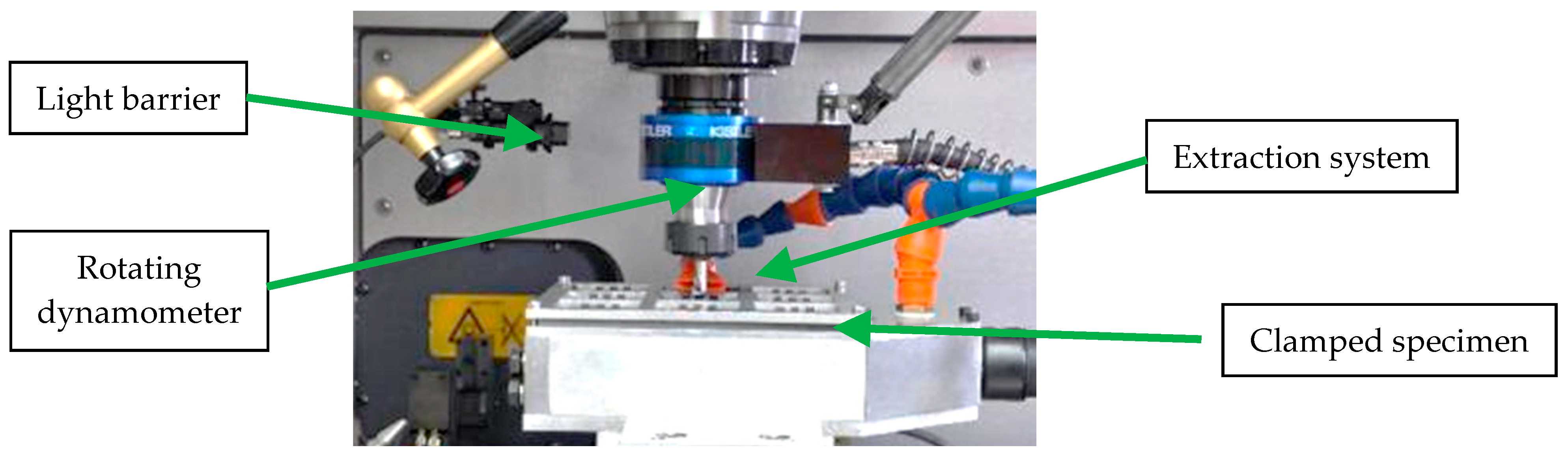
2. Experimental Setup

All experiments were performed on a conventional machining center. The forces and torque were determined using a rotating dynamometer. The FCA was calculated by determining the angle position of the main spindle to the fiber orientation by using a light barrier (cf. Figure 1). The specimens had the dimensions [mm] 200 × 200 × 5 for the bores with the diameter dtool = 10 mm, and [mm] 200 × 200 × 10 for the bores with the diameter dtool = 25.4 mm. The workpiece material is UD-CFPR (100% 0°), 60% fiber volume content (type of fibers: Dialead K63712) in epoxy resin. Each test in this paper was carried out three times, that is, replicated twice. In relation to the state of the art, the cutting speed for all tests was selected to be very low (vc = 0.63 m/min) in order to be able to apply the new strategies in Section 3.3, using the position control of the main spindle.
All bores were pre-drilled to avoid chisel edge effects (cf. Table 1). The delamination factor according to Chen [9] of peel-up delamination and push-out delamination of the pilot hole did not exceed 1.01. All instances of delamination were measured using a measuring light microscope, Makrolite from Vision Engineering. The illustration of a drill rotation in Section 3 is carried out under drill full engagement.
The following parameters have been implemented for this purpose.

3. Results

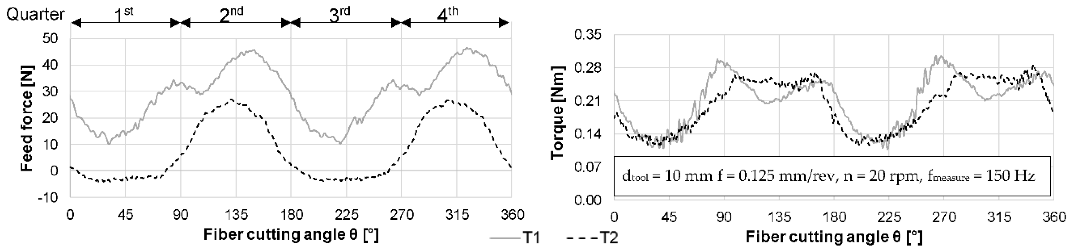
3.1. Comparison of the Different Drill Geometries
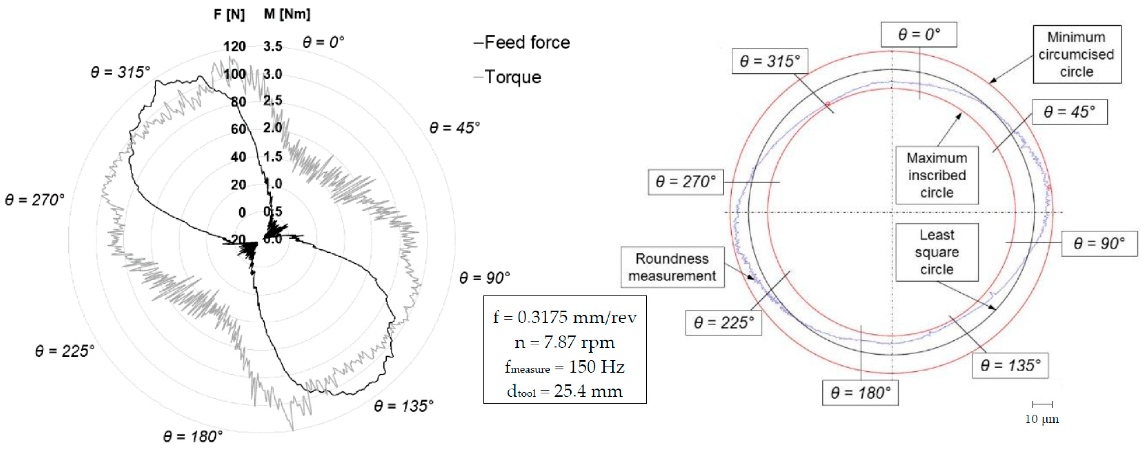
The feed force and torque of the drilling tests with different rake angles are compared with each other in Figure 2. Due to the different tool geometries it can be determined that different characteristics occur and that the fiber orientation has a strong influence on the progression of the tool loads.
Contrary to the research results of other researchers [13], the higher feed force was measured at the drill with lower point angle of σ = 85°. The chisel edge cannot influence the feed force progression because the bores were drilled with a pilot bore of dpilot = 1.2 mm. The basic level of feed force of the drill is higher with a smaller rake angle. The general course of the feed force and torque graphs can be explained as follows:
With a large rake angle γ, such as on tool T2, the major cutting edge grips under the fibers at θ = 0°, creating a small leading crack. The fibers run over the rake face and cause a negative feed force. This mechanism can be used to reduce delamination when the drill bit exits at a defined fiber cutting angle. Thus, the feed force would orient into the composite material that would support itself. Due to the described properties, the large rake angle is difficult to handle at the bore entrance. The cutting wedge peels up the first layer and encourages delamination at the drill entrance.
In the 2nd quarter the fibers are preloaded according to Pfeifroth [2], that is, the fibers are bilaterally clamped. The reduced stiffness across the fiber direction and the resulting spring back effect of the composite ensure an increase in feed force up to θ < 135°. In this range, the preload is dissolved by cutting on one side. The preloaded fibers can be separated more precisely by the cutting edge because they are fixed at both sides. This results in a high torque and good surface quality. The fiber cutting angle θ = 135° is equal to angle of 45° between the major cutting edge and the fibers. Here, most uncut fibers are located underneath the major cutting edge due to the three-dimensional cutting process. The feed force reaches its maximum due to the spring back effect of the composite.
The second torque maximum appears at θ = 180° because the maximum amount of fibers in radial direction is in contact in this cutting edge position. In the 3rd quarter there is no more preload on the fibers. They are clamped only on one side. As just described at 0° < θ < 90° a crack appears that constitutes the minimum of torque at θ = 225° because of the missing fiber preload. The uncut fibers glide elastically under the major cutting edge. Due to the superimposed feed movement they cause poor surface quality. The fibers fail because of bending stress, because of missing preload, and one-sided clamping.
Small rake angles induce high compressive forces on the fibers and the matrix material at θ = 0°. As a consequence, a break in the matrix material is evoked. The fibers and the broken matrix material are compressed in front of the cutting edge. At θ ≈ 30° the cutting process starts without initiating a leading crack. At θ = 90° the fibers cannot glide under the major cutting edge because of the small rake angle, but they are broken by the feed force. This causes a high feed force and high torque. The peeling up effect of the first layer on the top of the material does not occur, which leads to better quality at the bore entrance.

3.2. Bore Quality

Figure 3 shows the force and torque over one revolution during drilling with tool T3. The variabilities in the cutting force also result in roundness (cf. Figure 3, right) and surface errors. All cutting and geometrical parameters of tool T2 with Ø10 mm have been scaled on Ø25.4 mm to make the machining operations comparable. Due to the angles of the cutting part, just peel-up delamination occurs using tool T2 and T3. The push-out delamination is negligible when applying these tools.
In the 1st quarter the fibers are not cut, but as already described, a leading crack and the bending stress are breaking the fiber. This results in an enlargement of the diameter and larger delamination in this range of fiber cutting angle. The fibers are cut under preload in the range of 90° < θ < 180°. Due to this fact the fibers in the matrix material at the wall of the bore spring back elastically. During the following revolution, these fibers are pressing on the minor cutting edge causing the reduced bore diameter. Better surface quality is achieved with a lower delamination tendency. In a nutshell, the most significant material damage and the error in roundness occur in the areas of low feed force and torque.

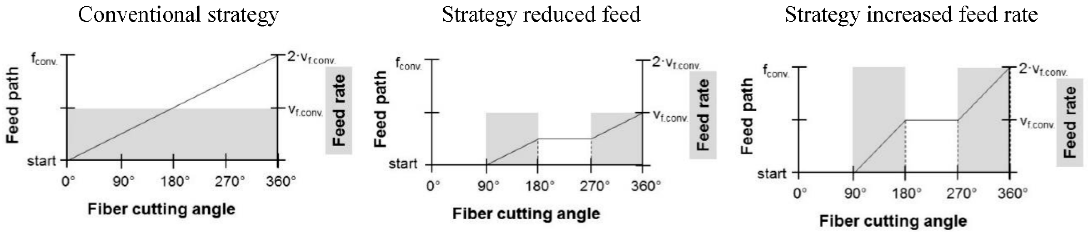
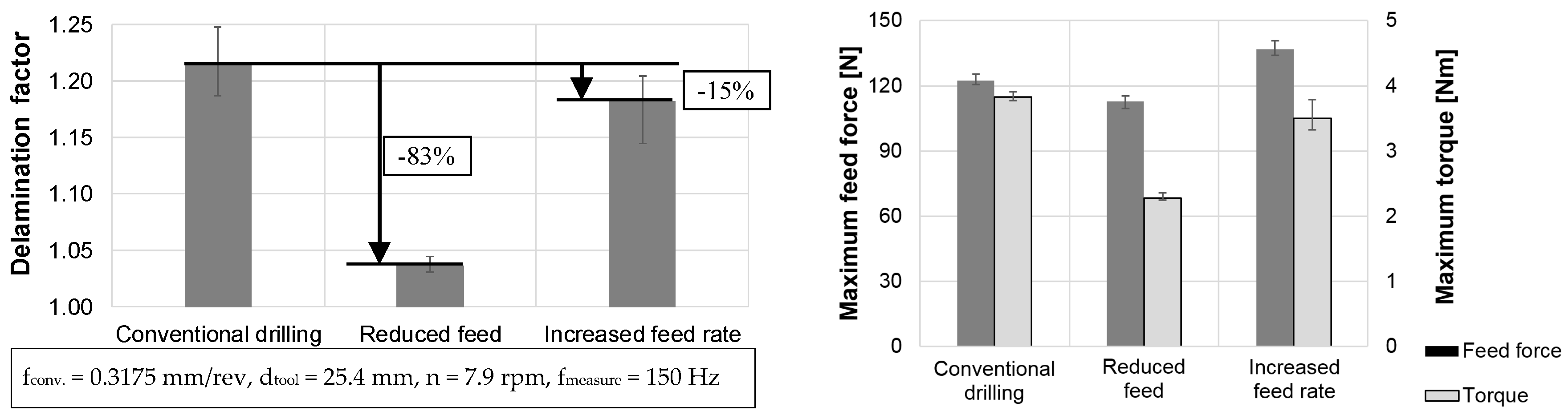
3.3. Strategy for Drilling in UD-CFRP

New feed strategies can be derived from the chip formation analysis of Section 3.1 to relieve the areas of poor quality. They describe that a feed movement is carried out only in the range of 90° ≤ θ ≤ 180°, whereby from θ = 0° to θ = 90° no feed movement takes place. Figure 4 visualizes these strategies. The black graph refers to the primary y-axis. The feed position “start” describes the starting point of feed movement in feed direction. The feed position “fconv.” is equal to the end point of feed movement in feed direction after one revolution of the drill regarding the conventional strategy. The feed rate is displayed by the grey columns, which refer to the secondary y-axis.
This new approach should discharge the delamination-critical area of 0° ≤ θ ≤ 90° and enhance the surface and machining quality. With the strategy reduced feed (cf. Figure 4, middle) the resulting feed of one revolution is equal to half of the feed using the conventional strategy. An adjustment to the same primary processing time is possible. Twice conventional feed must be used (cf. Figure 4, right).
Figure 5 represents the results of the application of the new strategy in an experimental test series compared to the conventional drilling strategy. As a result of the new strategy, the delamination factor at the bore entrance according to Chen can be significantly reduced using the feed rate of the conventional process (cf. Figure 5, left). The reduction of primary process time by increasing the cutting speed should be checked separately. Adjusting the feed to achieve the same primary processing time as in the conventional process causes larger delamination than the previously described strategy. An improvement in roundness could not be determined.

4. Summary, Conclusions, and Outlook

The described process conditions and results can be summarized as follows:
  • Very different chip formation mechanisms appear during one drill revolution, whereby the 1st and the 3rd quarter are critical due to the resulting surface and machining quality.
  • A large rake angle induces good quality at bore exit, but poor quality on the upper side of the composite material.
  • The machined bore has an eccentricity related to surface quality, delamination, and fiber cutting angle.
  • Using an adapted feed strategy, the delamination can be reduced by up to 83%.
These approaches can be used in further research, especially in application of ultrasonic assisted drilling with longitudinal oscillation. Applying other drill bits, and additional test series to investigate the effect of the new strategy on the bore exit are possible. The applicability of cutting force modelling on the described strategy has to be investigated separately (cf. References [31,32,33]).

Author Contributions

Investigation, K.S.; Project administration, M.D.; Supervision, M.P.

Funding

This research was funded by AiF Projekt GmbH (project executing organization of Federal Ministry for Economic Affairs and Energy (German: Bundesministerium für Wirtschaft und Energie)), grant number: ZF4028017AT6.

Conflicts of Interest

The authors declare no conflict of interest.

References

  1. Teti, R. Machining of Composite Materials. CIRP Ann. 2002, 51, 611–634. [Google Scholar] [CrossRef]
  2. Pfeifroth, T. Beitrag zur Verbesserung der Spanenden Bohrbearbeitung von CFK auf Basis von Schädigungsmechanismen. Ph.D. Thesis, Universität Stuttgart, Stuttgart, Germany, 2014. [Google Scholar]
  3. Eneyew, E.D.; Ramulu, M. Experimental study of surface quality and damage when drilling unidirectional CFRP composites. J. Mater. Res. Technol. 2014, 3, 354–362. [Google Scholar] [CrossRef]
  4. Haeger, A.; Meinhard, D.; Lissek, F.; Kaufeld, M.; Hoffmann, M.J.; Schneider, G.; Knoblauch, V. Interaction between laminate quality, drilling-induced delamination and mechanical properties in machining of carbon fibre reinforced plastic (CFRP). Materialwissenschaft und Werkstofftechnik 2016, 47, 997–1014. [Google Scholar] [CrossRef]
  5. Hejjaji, A.; Singh, D.; Kubher, S.; Kalyanasundaram, D.; Gururaja, S. Machining damage in FRPs. Compos. Part A Appl. Sci. Manuf. 2016, 82, 42–52. [Google Scholar] [CrossRef]
  6. Hintze, W.; Hartmann, D.; Schütte, C. Occurrence and propagation of delamination during the machining of carbon fibre reinforced plastics (CFRPs)—An experimental study. Compos. Sci. Technol. 2011, 71, 1719–1726. [Google Scholar] [CrossRef]
  7. Hintze, W.; Hartmann, D. Modeling of Delamination During Milling of Unidirectional CFRP. Procedia CIRP 2013, 8, 444–449. [Google Scholar] [CrossRef]
  8. Liu, D.; Tang, Y.; Cong, W.L. A review of mechanical drilling for composite laminates. Compos. Struct. 2012, 94, 1265–1279. [Google Scholar] [CrossRef]
  9. Chen, W.-C. Some experimental investigations in the drilling of carbon fiber-reinforced plastic (CFRP) composite laminates. Int. J. Mach. Tools Manuf. 1997, 37, 1097–1108. [Google Scholar] [CrossRef]
  10. Davim, J.P.; Rubio, J.C.; Abrao, A.M. A novel approach based on digital image analysis to evaluate the delamination factor after drilling composite laminates. Compos. Sci. Technol. 2007, 67, 1939–1945. [Google Scholar] [CrossRef]
  11. Faraz, A.; Biermann, D.; Weinert, K. Cutting edge rounding: An innovative tool wear criterion in drilling CFRP composite laminates. Int. J. Mach. Tools Manuf. 2009, 45, 1185–1196. [Google Scholar] [CrossRef]
  12. Pramod, R.; Basavarajappa, J.; Davim, J. A review on investigations in drilling of fiber reinforced plastics. In Machinability of Fibre-Reinforced Plastics; De Gruyter: Berlin, Germany; München, Deutschland; Boston, MA, USA, 2015. [Google Scholar]
  13. Heisel, U.; Pfeifroth, T. Influence of Point Angle on Drill Hole Quality and Machining Forces when Drilling CFRP. Procedia CIRP 2012, 1, 471–476. [Google Scholar] [CrossRef]
  14. Aurich, J.C.; Kirsch, B.; Müller, C.; Heberger, L. Quality of Drilled and Milled Rivet Holes in Carbon Fiber Reinforced Plastics. Procedia CIRP 2014, 24, 56–61. [Google Scholar] [CrossRef]
  15. Davim, J.P.; Reis, P. Study of delamination in drilling carbon fiber reinforced plastics (CFRP) using design experiments. Compos. Struct. 2003, 59, 481–487. [Google Scholar] [CrossRef]
  16. Abrão, A.M.; Rubio, J.C.; Faria, P.E.; Davim, J.P. The effect of cutting tool geometry on thrust force and delamination when drilling glass fibre reinforced plastic composite. Mater. Des. 2008, 29, 508–513. [Google Scholar] [CrossRef]
  17. Gaitonde, V.N.; Karnik, S.R.; Rubio, J.C.; Correia, A.E.; Abrao, A.M.; Davim, J.P. Analysis of parametric influence on delamination in high-speed drilling of carbon fiber reinforced plastic composites. J. Mater. Proc. Technol. 2008, 203, 431–438. [Google Scholar] [CrossRef]
  18. Abrão, A.M.; Faria, P.E.; Rubio, J.C.; Reis, P.; Davim, J.P. Drilling of fiber reinforced plastics: A review. J. Mater. Proc. Technol. 2007, 186, 1–7. [Google Scholar] [CrossRef]
  19. Pecat, O.; Rentsch, R.; Brinksmeier, E. Influence of Milling Process Parameters on the Surface Integrity of CFRP. Procedia CIRP 2012, 1, 466–470. [Google Scholar] [CrossRef]
  20. Karpat, Y.; Bahtiyar, O. Comparative Analysis of PCD Drill Designs during Drilling of CFRP Laminates. Procedia CIRP 2015, 31, 316–321. [Google Scholar] [CrossRef]
  21. Grilo, T.J.; Paulo, R.M.F.; Silva, C.R.M.; Davim, J.P. Experimental delamination analyses of CFRPs using different drill geometries. Compos. Part B Eng. 2013, 45, 1344–1350. [Google Scholar] [CrossRef]
  22. Henerichs, M.; Voss, R.; Kuster, F.; Wegener, K. Machining of carbon fiber reinforced plastics: Influence of tool geometry and fiber orientation on the machining forces. CIRP J. Manuf. Sci. Technol. 2014, 9, 136–145. [Google Scholar] [CrossRef]
  23. Tsao, C.C.; Hocheng, H. The effect of chisel length and associated pilot hole on delamination when drilling composite materials. Int. J. Mach. Tools Manuf. 2003, 43, 1087–1092. [Google Scholar] [CrossRef] [Green Version]
  24. Sorrentino, L.; Turchetta, S.; Bellini, C. A new method to reduce delaminations during drilling of FRP laminates by feed rate control. Compos. Struct. 2018, 186, 154–164. [Google Scholar] [CrossRef]
  25. Hocheng, H.; Tsao, C.C. Effects of special drill bits on drilling-induced delamination of composite materials. Int. J. Mach. Tools Manuf. 2006, 46, 1403–1416. [Google Scholar] [CrossRef]
  26. Tsao, C.C.; Hocheng, H. Parametric study on thrust force of core drill. J. Mater. Proc. Technol. 2007, 192, 37–40. [Google Scholar] [CrossRef]
  27. De Lacalle, L.L.; Lamikiz, A.; Sánchez, J.A.; De Bustos, I.F. Recording of real cutting forces along the milling of complex parts. Mechatronics 2006, 16, 21–32. [Google Scholar] [CrossRef]
  28. Schütte, C. Bohren und Hobeln von Kohlenstofffaserverstärkten Kunststoffen unter besonderer Berücksichtigung der Schneide-Faser-Lage. Ph.D. Thesis, Technische Universität Hamburg-Harbug, Hamburg, Germany, 2014. [Google Scholar]
  29. Lopresto, V.; Caggiano, A.; Teti, R. High Performance Cutting of Fibre Reinforced Plastic Composite Materials. Procedia CIRP 2016, 46, 71–82. [Google Scholar] [CrossRef]
  30. Wang, X.M.; Zhang, L.C. An experimental investigation into the orthogonal cutting of unidirectional fibre reinforced plastics. Int. J. Mach. Tools Manuf. 2003, 10, 1015–1022. [Google Scholar] [CrossRef]
  31. Chen, L.; Zhang, K.; Cheng, H.; Qi, Z.; Meng, Q. A cutting force predicting model in orthogonal machining of unidirectional CFRP for entire range of fiber orientation. Int. J. Adv. Manuf. Technol. 2016, 89, 833–846. [Google Scholar] [CrossRef]
  32. Voß, R. Fundamentals of Carbon Fibre Reinforced Polymer (CFRP) Machining. Ph.D. Thesis, ETH Zurich, Zürich, Switzerland, 2017. [Google Scholar]
  33. Lopez de Lacalle, N.; Lamikiz, A.; Campa, F.J.; Valdivielso, A.F.; Etxeberria, I. Design and Test of a Multitooth Tool for CFRP Milling. J. Compos. Mater. 2009, 43, 3275–3290. [Google Scholar] [CrossRef]
Figure 1. Experimental setup.
Jmmp 02 00046 g001
Figure 2. Comparison of feed force (left) and torque (right) during drilling with pilot bore using two different tool geometries.
Jmmp 02 00046 g002
Figure 3. Cutting forces and torque graphs of tool 3 compared to the circularity of the machined hole.
Jmmp 02 00046 g003
Figure 4. Strategies for drilling in unidirectional carbon fiber-reinforced plastics (UD-CFRP) with adapted feeds and feed rates.
Jmmp 02 00046 g004
Figure 5. Delamination factor (bore entrance) (left) and maximum tool loads applying the different feed strategies (right).
Jmmp 02 00046 g005
Table 1. Parameters and experimental setup for the test series.
Tool No.Diameter
dtool
AnglesPilot Hole
dpilot
ToolMachine and MeasurementFiber Cutting Angle (FCA) θ
T110 mmσ = 85°
γ ≈ 4°
β ≈ 76°
1.2 mmTwist drill, solid carbide, uncoated, dry machiningDMG Mori DMC 850 V, Kistler rotating dynamometer 9170A Jmmp 02 00046 i001
T210 mmσ = 118°
γ ≈ 38°
β ≈ 40°
T325.4 mmσ = 118°
γ ≈ 38°
β ≈ 40°
3.05 mm

