Hybrid Woven Glass Fibre Fabric-Multi-Walled Carbon Nanotube-Epoxy Composites Under Low Rate Impact

Department of Mechanical Engineering Sciences, Faculty of Engineering and Physical Sciences, University of Surrey, Guildford, Surrey GU2 7XH, UK
*
Author to whom correspondence should be addressed.
J. Compos. Sci. 2017, 1(1), 10; https://doi.org/10.3390/jcs1010010
Submission received: 27 July 2017
/
Revised: 15 August 2017
/
Accepted: 16 August 2017
/
Published: 1 September 2017
Abstract
:This research work addresses the issue of developing light composite materials with increased ability for impact energy absorption. Novel, hybrid plain woven glass fibre fabric-epoxy laminates with multi-walled carbon nanotube (MWNT) interlayers were fabricated in this study so that (a) only a few MWNT interlayers were placed close to the face of the laminate to be subjected to impact and (b) the interlayers were fabricated via innovative wide-line electrospinning of MWNT/epoxy/solvent solutions, depositing a mixture of aligned fibres and spray on the woven glass fibre fabrics; the laminate was then fabricated via resin transfer moulding (RTM). Hybrid nano-micro-composite laminates with 0.15 wt% MWNT were prepared with this method and were subjected to single low rate impact tests. It was found that the optimised hybrid laminates had 22% greater total penetration energy translated to 15% weight reduction in the laminate armour for an equivalent amount of energy penetration.
1. Introduction
The aim of this work has been to increase the impact penetration energy of a plate while maintaining very low weight. The main idea to accomplish this was to use a very small amount of nanomaterials or nanofibres that would increase the absorbed impact energy via different mechanisms utilising the large specific surface area of the nanomaterial.
Carbon nanotubes (CNTs) have been investigated in composite materials, specifically to increase the electrical conductivity of the polymer matrix by adding a very small amount of multi-walled carbon nanotubes (MWNTs) in the range 0.1–7 wt% [1,2,3]. With regards to mechanical properties, the addition of CNTs to polymers has been reported to raise the glass transition temperature and modulus [2,4,5], while the strength may be improved or worsened, depending on whether the polymer is a brittle thermoset [5,6] or a thermoplastic [4].
Continuous fibre-polymer composites fail under different damage modes under impact: intra-ply cracks, delamination and fibre fracture [7] or in even more detail: matrix cracking, surface micro-buckling, delamination, ply shear-out and fibre fracture [8]. Hence, any methods to improve matrix properties and delamination are under consideration for increasing the required penetration energy under impact: these include 3D weaving and stitching [9], matrix toughening by adding nanoparticles or clay nanoplatelets [10,11,12,13,14,15] or nanowhiskers [16,17]. On the other hand, in aiming at maximum absorption and dissipation of impact energy, the following mechanisms may be considered: plastic deformation of tough materials and structures, hyperelastic, viscoelastic or plastic material layers such as polyurea and other energy-dissipation layers such as foams [18].
Carbon nanotubes are of interest as a reinforcement against impact as they have a large aspect ratio and can form a network. Dispersion of CNTs is most important to realise the benefits of the nano-effects [19,20]. For this reason, a solvent is frequently used as an aid for the dispersion at high shear [2,21]. Although the concept of multi-scale reinforcement in composite materials has been thought advantageous, on the basis of biocomposites such as bone, it is very difficult to fully infiltrate MWNTs through a continuous fibre reinforcement, following a feasible and cost-effective process. For example, injection of a MWNT-resin system in the resin transfer moulding (RTM) of fabric reinforced composites often results in the filtering of MWNTs by the fibre fabric laid in the mould. Hence, the fabrication of interlayers of MWNTs within the laminate has been considered in this study. Karapappas et al. [22] reported a 45% increase of the Mode II fracture toughness by adding 0.5% CNTs in a CFRP but Kostopoulos et al. [23] reported very little improvement in the penetration energy under low speed impact. Inam et al. [24] added amino-functionalised double-walled carbon nanotubes (DWCNT-NH2) in plain woven carbon fibre fabric-epoxy composites manufactured by vacuum infusion in a flexible bag at a Vf = 0.55 on average. The optimum composition for impact included 0.05 wt% DWCNT-NH2 which raised the absorbed energy under slow speed impact by only 5.7% compared to the carbon fabric-epoxy laminates without CNTs. Wan Hanif et al. [25], after having determined that 1 wt% MWNTs was the optimum content to improve the fracture toughness of epoxy, used this composite matrix in the manufacturing of Twaron/Epoxy/MWNT composites using hand layup with vacuum bagging assist; some of these composites exhibited up to four times increased energy absorption for medium projectile speeds (384 and 412 m/s) compared to those without MWNTs.
Grujicic et al. [26] carried out computational modelling of the impact process and concluded that the optimum configuration for a CNT-loaded continuous glass fibre laminate requires a 100 μm layer of MWNTs near the front face of a laminated structure. Spraying of MWNT solutions has been used as a means of achieving well dispersed MWNT coatings [27]. Palazzetti [28] investigated laminates of 0/90 woven carbon fibre/epoxy resin prepregs with interleaves of electrospun nylon 6,6 nanofibres placed either symmetrically (two interleaves by the front and two interleaves by the back face of the laminate) or asymmetrically comprising three interleaves by the back face of the laminate. He found that the thickness of interleaves in the range of 25–50 μm did not affect the laminate performance, these interleaves brought improvements by up to 24% for Mode II fracture toughness, no difference in the impact curves, reduction of absorbed impact energy for impact energy values of 3 and 6 J and about a 13% increase in the absorbed impact energy for the impact energy value of 12 J for the asymmetric interleaf architecture (against an 8% increase in the absorbed impact energy for the symmetric interleaf architecture).
In this study, electrospun MWNT-epoxy fibres have been explored on the basis of the idea that MWNT orientation in electropsun MWNT interlayers can also be exploited. Viscosity and viscoelastic effects are very important in electrospinning: a low viscosity solution jet breaks into a spray during electrospinning [29] whereas a high viscosity solution may dry at the tip of the feed needle [30]. Hence, the electrospinning process was fine-tuned in this study to achieve a high voltage deposition of a mixture of oriented MWNT/epoxy nanofibres and MWNT/epoxy spray on a plain woven glass fibre fabric. Four MWNT coated fabric layers were laid in pairs within an 11 ply assembly near the face of intended impact (as optimised theoretically by Grujicic et al. [26]), so that the MWNT coatings in each pair were face-to-face at a 0/90 configuration. Laminates were fabricated by RTM and were tested in single low-speed impact tests.
2. Materials and Methods
An E-glass fibre plain woven fabric Y0212 [31] from Fothergill Engineered Fabrics has been used in this study of areal density 0.546 kg/m2, nominal thickness 0.5 mm, 670 ends/m in the warp direction and 630 pics/m in the weft direction. The used fabric has a methacrylato chromic chloride finish which allows fibre compatibility and adhesion to epoxide and other organic systems, such as polyester and vinylester resin, and provides essential handling properties. The resin system used was Araldite® LY 564 epoxy resin, which contained a reactive diluent, and hardener HY 2954 (cycloaliphatic amine hardener) from CIBA polymers at a weight ratio of 100:35 Araldite®/hardener. Elicarb® multi-walled carbon nanotubes (MWNTs) from Thomas Swan were used, of 10–30 nm average diameter and microns length. A mixture of butanone with 1-methoxy-2-propanol in 3:1 weight ratio, respectively, was used as a solvent for the electrospinning of MWNT-epoxy fibres (solvents from Sigma Aldrich, St. Louis, MO, USA).
The MWNT suspensions contained 1 wt% MWNT in the butanone/1-methoxy 2 propanol solvent mixture at 3:1 weight ratio [32]. The mixture was stirred in two stages: (a) ultrasonic bath stirring for 1 h and (b) high speed shear stirring in a homogeniser at 104 rpm for 1 h. After the stirring process, the MWNT solution was combined with the epoxy solution part to form the suspension to be used in the electrospinning process. The optimum ratio of Araldite® and hardener to MWNT solution was obtained experimentally, as will be described in Section 3.
The electrospinning involved electrospinning of the MWNT-epoxy-solvent mixture solution onto a glass fibre woven fabric wrapped around the rotating drum collector. Figure 1 presents a diagram of the electrospinning rig. The electrospinning rig consisted of a rotating drum collector with parallel wires lengthwise [33], a high voltage power supply and a syringe pump. The syringe system consisted of a syringe pump, a 5 mL syringe, a feed tube and an exit needle. The syringe pump operated at a constant flowrate (typically 4 mL/hr), and fed a prismatic metallic hopper with a perforated bottom edge: this is an innovative design of a wide-line feed of electrospinning lines for the homogeneous coverage of the whole fabric width covering the drum collector. The high voltage power supply was operated at 30 kV. The negative electrode was connected to the drum collector. The positive electrode was connected to the metallic hopper, the lower feed edge of which was placed 180 mm above the drum collector. The drum collector was rotated during the experiment at a constant speed of 2 rpm using an electro-motor. The working area of the drum collector was covered with a Melinex film to avoid any contact of Araldite/MWNT/solvent solution with the metal parts of the drum. The rotating drum collector with the charged, parallel wires lengthwise ensured orientation of the electrospun MWNT-epoxy fibres perpendicularly to the drum wires.
For the manufacture of laminates, Araldite epoxy resin and hardener were weighed on an electronic balance in separate beakers and left in a vacuum oven at 50 °C for degassing for 3 h. Laminates of 11 fabric layers were fabricated by RTM in rectilinear flow mode under 2 bar constant inlet pressure and distributed flow feed. After the RTM run was completed, the laminate was left in the mould for 24 h to cure at room temperature and then it was post-cured in the oven at 140 °C for 4 h. The hybrid laminates contained about 0.15 wt% MWNTs.
The so-fabricated laminates were cut into discs of 140 mm diameter for impact testing in a CRAG test rig (defined by the composite Research Advisory Group-CRAG) on an Instron mechanical testing machine. The impactor used in these experiments was a marble ball of 15.6 mm diameter moved at a speed of 2 mm/s. A digital camcorder was installed inside the rig cage in order to record the impact damage event. The zero point in the impact testing force-deformation-time relation was obtained by steady driving the impactor to the specimen surface. A sheet of paper was placed between the specimen surface and the impactor. The impactor was driven to the specimen surface and stopped at the moment when the sheet of paper was clamped between the marble ball and the specimen surface. This position of the impactor was denoted as the zero point for the data collected by the computer connected to the Instron machine. According to safety regulations, the specimens containing carbon nanotubes were impact tested with additional protection measures. In order to avoid the release of any nanoparticles in the atmosphere, a multi-layer plastic protective assembly was wrapped and secured around the impact plates, enclosing all the distance between the impact plates but totally loose in the impact direction (vertical direction), so it did not affect the impact test in any way.
3. Results
3.1. Optimisation of the MWNT-Epoxy Electrospinning Process
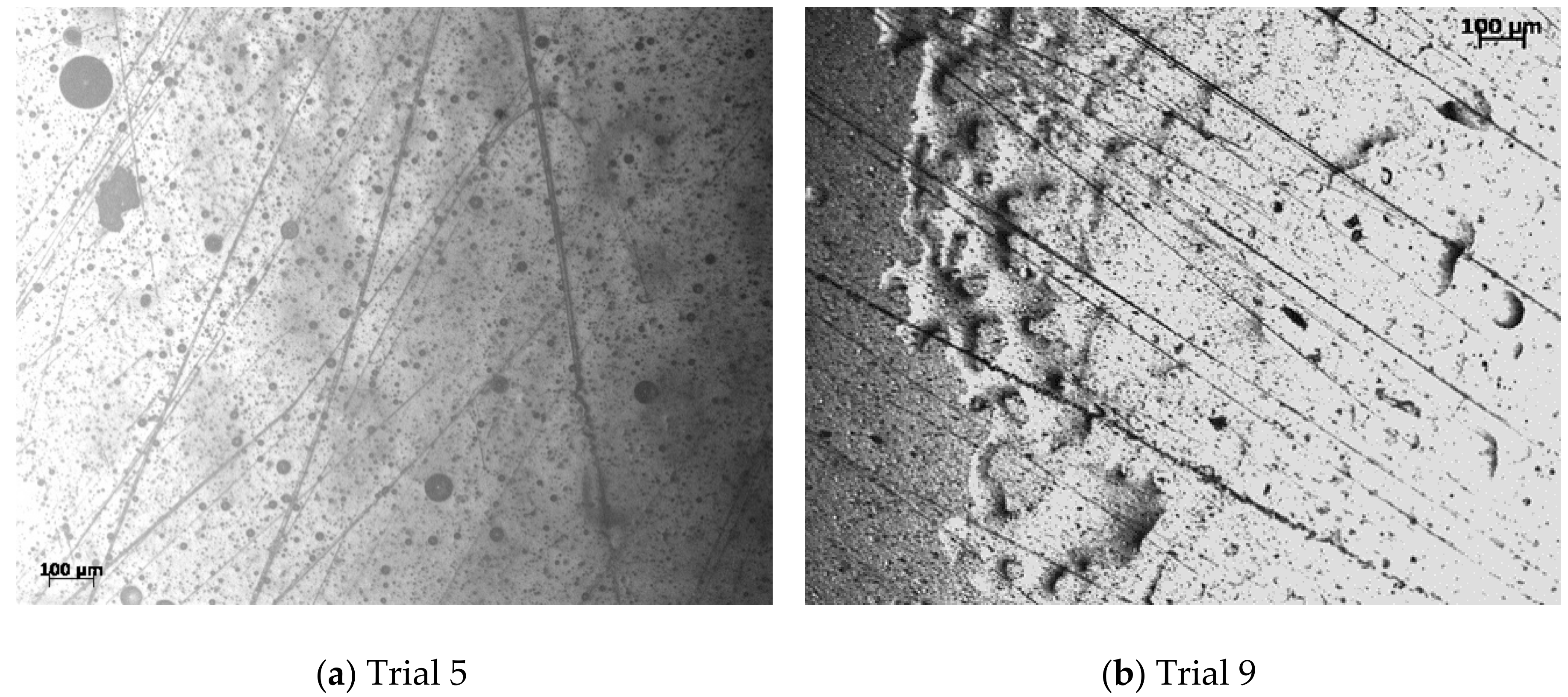
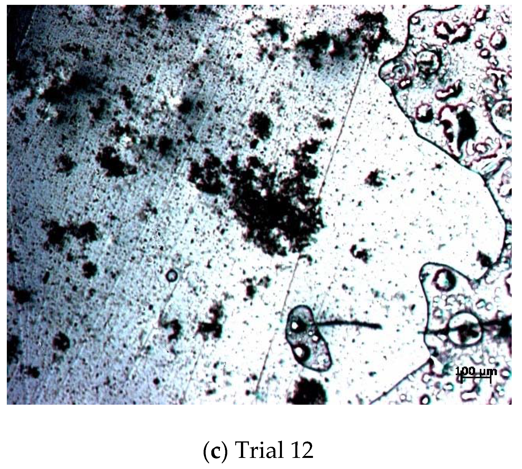
The first task was to optimise the composition of the feed solution composition to achieve continuous fibres in the electrospinning. In this section the materials, parameters and conditions of the electrospinning experiments are summarised together with a brief description of the results in order to select the optimum concentrations of the CNT-Epoxy solutions. The feed rate of the syringe pump was an additional varied parameter in these first electrospinning trials, while all other process parameters were kept constant at the values reported in Section 2. Table 1 summarises the results for each combination of material composition and feed flow rate. The epoxy used in this study is a low viscosity RTM epoxy, so that the electrospun fibres will be compatible with the epoxy to be injected in the RTM of laminates. In this case, it seems that the full epoxy-hardener mixture has no viscoelastic features usually needed to yield successful electrospinning of fibres, and instead forms and deposits a spray of droplets. A higher viscosity epoxy 300 and its typical hardener was also used (trial 3 in Table 1) without successful electrospinning of fibres. Hence, epoxy resin only-MWNT solutions were tried without the hardener, as the epoxy resin alone retains its viscoelastic character. The best parameters for a high concentration of electrospun fibres were those of trial 5, repeated in trial 9 to check process repeatability. Figure 2 illustrates the electrospun products in trials 5 and 9, where it can be seen that the process results in a mixture of electrospun MWNT/epoxy fibres and MWNT/epoxy spray, where the epoxy is just uncured Araldite resin. This resin is expected to be mixed with the curing epoxy-hardener mixture injected during RTM and curing is expected during the RTM stage. The product of trial 12 is also presented in Figure 2 and this involves Araldite/hardener as the feed materials, which means that the electrospun fibres are composite materials of MWNT/cured epoxy. The material composition and processing conditions for trial 12 are equivalent to those for trials 5 and 9.
3.2. Composite Laminates for Impact Testing
11-Layer plain weave glass fibre fabric-epoxy laminates were fabricated and tested as a reference, in the same way as the hybrid MWNT-plain weave glass fibre fabric-epoxy laminates. Figure 3 presents the thickness data distribution for the laminate disc used in impact testing, averaging to 4.76 mm thickness which corresponds to a fibre volume fraction Vf = 49.3%, where Vf was determined from burn off tests and was in total agreement with values calculated from the relation
where H is the laminate thickness, N is the number of plies, ρa is the areal density of the fabric = 0.546 kg/m2 and ρf is the density of the E-glass fibre = 2560 kg/m3.
Vf = (N ρa)/(ρf H)
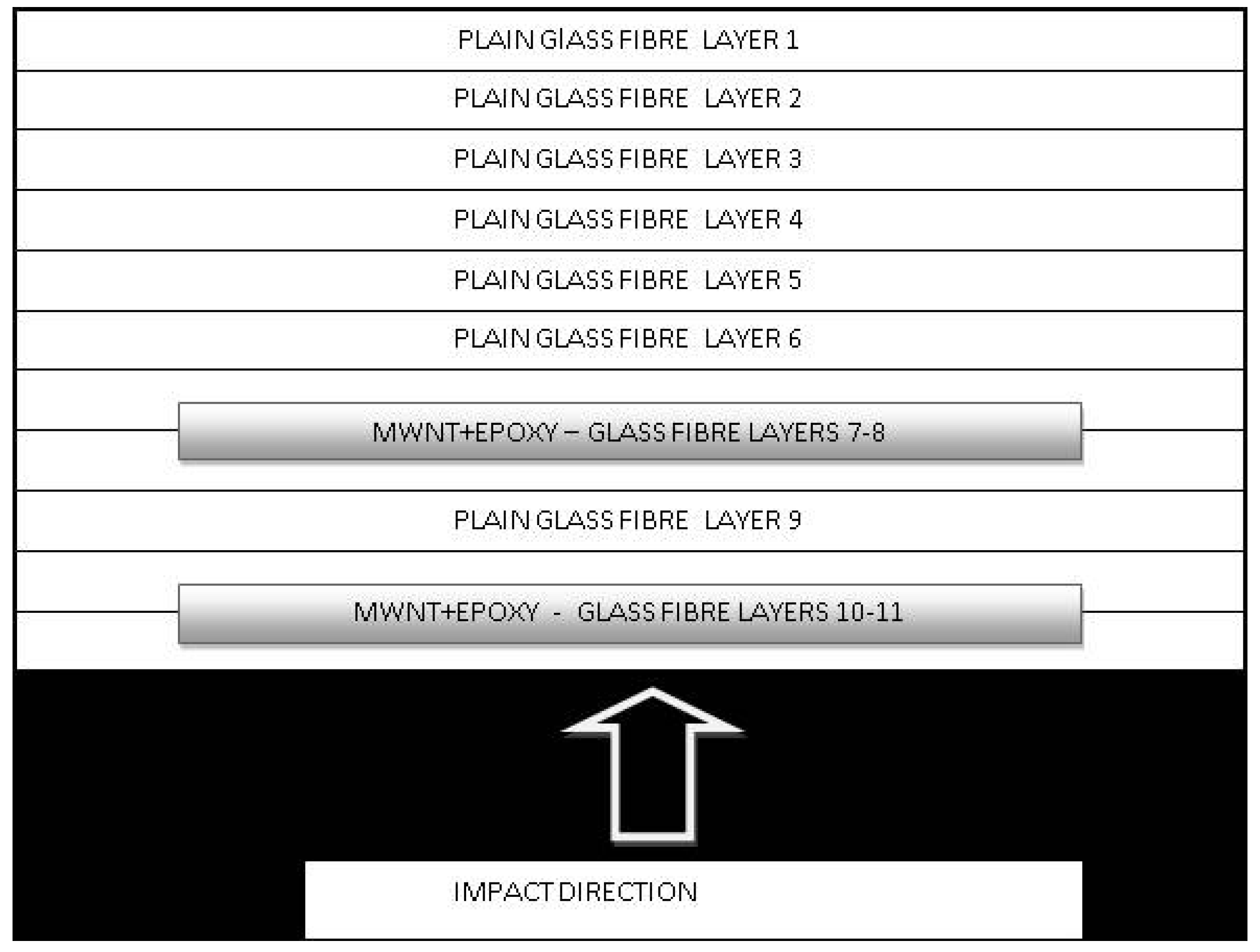
The architecture of the hybrid glass fibre fabrics-MWNT-epoxy laminates is presented in the diagram of Figure 4: it can be seen that, for each laminate, four glass fibre fabrics were prepared with electrospun MWNT-epoxy fibres/spray on one side of each of these four fabrics. Then, the fabrics were laid on the RTM mould, so that the adjacent MWNT-glass fibre fabrics were laid with the MWNT sides face-to-face at 0/90, as shown in Figure 4. The RTM mould was then closed and the curing epoxy resin mixture was injected and let to cure and post-cure as described in Section 2. The placement of the MWNT coated fabrics near the face of the impact was inspired from results of dynamic finite element analysis (FEA) simulations [26] where it was concluded that MWNT interlayers near the impact face were more effective than equally distributed MWNT interlayers between all fabric faces.
Figure 5 presents the thickness distribution for two hybrid laminates tested under impact: a glass fibre fabric-electrospun MWNT/Araldite-epoxy laminate and a glass fibre fabric-electrospun MWNT/Araldite/hardener-epoxy laminate, corresponding to an average fibre volume fraction of 44.07% and 43.8%, respectively.
3.3. Impact Testing Results
Single impact tests were performed where a marble ball impactor of 15.6 mm diameter was driven through the specimen surface once at a set speed of 2 mm/s. When penetration was fully completed, the impactor was driven back to the start position.
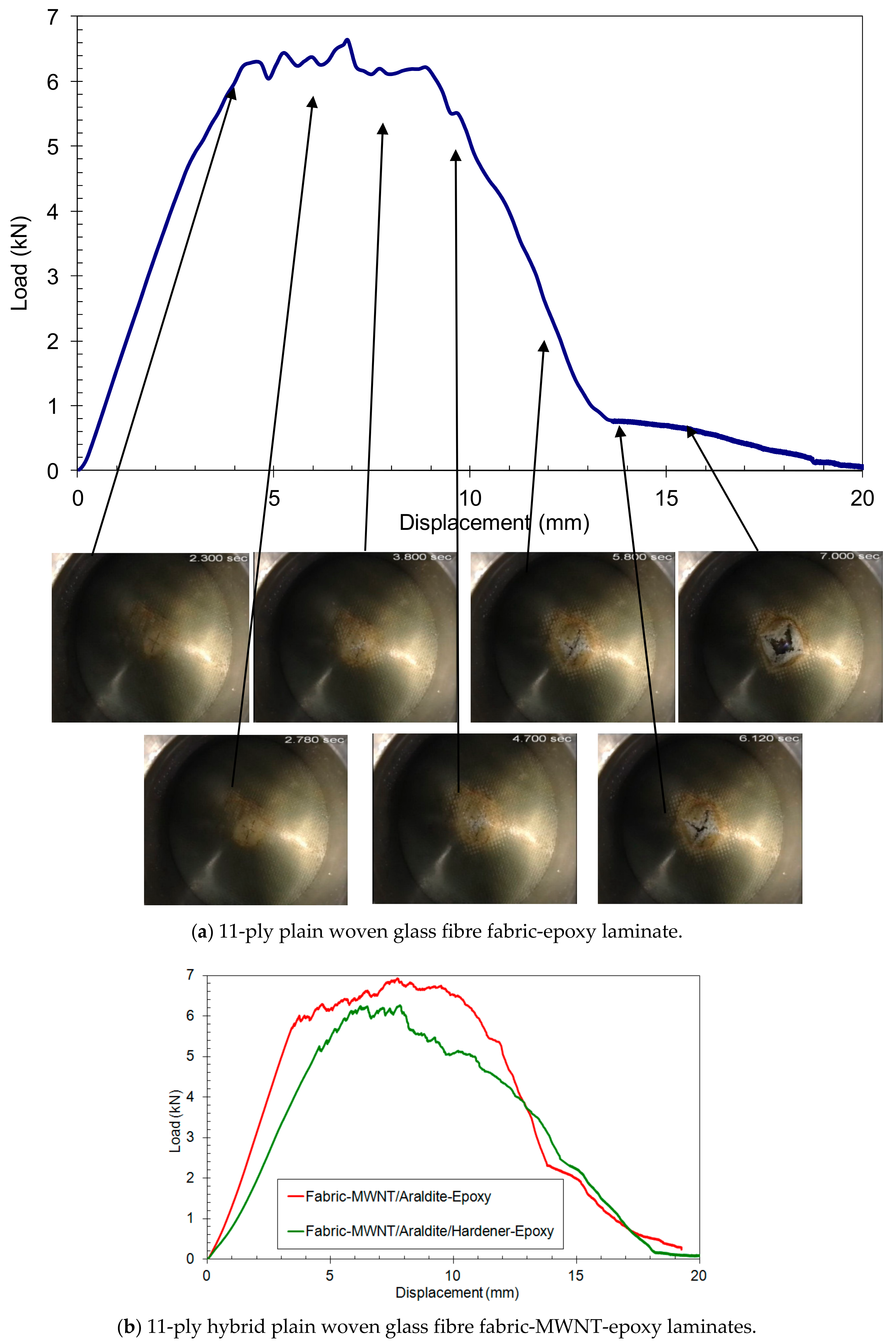
Figure 6a presents the load-versus displacement curve from the single impact test of an 11-ply plain woven glass fibre fabric-epoxy specimen (average: H = 4.76 mm, Vf = 49.3%). As the impactor makes contact with the specimen surface, there is an initial linear stress-strain region up to a displacement of 2 mm, whereby matrix cracking starts at that point. A small “bump” in the load-displacement curve at about 3 mm indicates the start of delamination at that point. Overall, the load increases rapidly to 6.2 kN at a displacement of 4 mm. At this point, the load begins to fluctuate significantly indicating fibre failure. This is until the load drops sharply after 9.6 mm displacement. This can be explained by the fact that the equator of the impactor has penetrated through the specimen. However, the specimen continues to be impacted while the load is decreasing with some further fibre failure. At the time when the impactor achieves 14 mm displacement, the bulk of the penetration is almost finished. The section of the graph between 14 and 20 mm presents the phase when the back face of the impactor goes through the opening of the laminate and it is characterised mainly by friction of the impactor. The maximum load on the specimen is 6.6 kN.
Snapshots from the video of the impact testing are presented in Figure 6a at selected points of the load-displacement curve for damage observation. At the 4 mm displacement point, a central white/gray damage area indicates debonding and delamination. With a further displacement to 6 mm, the damage area increases while a central white delamination area appears. At 8 mm displacement, there is an increase of both the overall damage area and the central delamination area and the first fibre break up was observed on the back face of the impacted specimen. At 12 mm displacement, the star formation of the fibre fracture area can be clearly seen. At the 14 and 16 mm displacement points, the penetration continues until the specimen is fully penetrated.
Figure 6b displays the load-displacement curves for the two types of hybrid laminates. The impact was applied to the side close to the MWNT containing layers of the specimen, as shown in Figure 4. With regards to the hybrid plain woven fabric-electrospun MWNT/Araldite/hardener-epoxy laminate, there is an initial linear load-displacement part up to a displacement of about 3 mm (Figure 6b), indicating the start of matrix cracking at that point. The load increases rapidly with the impactor displacement up to 4.7 mm at which point the first load fluctuation appears indicating the start of fibre fracture. As the displacement increases from 4.7 to 6.5 mm, the load continues to rise but with fluctuations indicating further fibre fracture. The load falls after a displacement of 8 mm with some fluctuations and bumps, indicating fibre failure and delaminations until the displacement reaches 10.9 mm. At this position, the equator of the impactor has penetrated through the specimen and the impactor has broken all the layers in the laminate. Further displacement indicates a decrease in load as the impactor moves through the specimen. In the graph section of 15 to 20 mm displacement, the predominant mechanism is friction between the impactor and the opening of the laminate. The maximum load is 6.2 kN.
With regards to the hybrid plain woven fabric-electrospun MWNT/Araldite-epoxy laminate, the load increases rapidly up to 3.7 mm displacement (Figure 6b) when the first load fluctuations appear. In the period between 3.7 and 7.7 mm displacement, the load continues increasing more steadily with large “bump” fluctuations, possibly indicating fibre failures, and small “narrow” fluctuations, possibly indicating delaminations or even nanofibre failures. The next section between 7.7 and 11 mm can be characterised by the stopping of the load increase while there are still large “bump” and “narrow” fluctuations. At 11 mm displacement, all layers are damaged and at that point the load starts decreasing. The maximum load on the specimen is 6.9 kN.
As can be seen in Figure 6b, both the Young’s modulus and strength of the hybrid fabric-electrospun MWNT/Araldite-epoxy laminate are relatively higher than that of hybrid fabric-electrospun MWNT/Araldite/hardener-epoxy laminate, amounting to a 0.7 kN difference in the maximum load. Most importantly, the load in the hybrid fabric-electrospun MWNT/Araldite-epoxy laminate is not reduced after achieving its maximum point, and it is still above 6.5 kN during a further 2 mm displacement. On the other hand, the load in the hybrid fabric-electrospun MWNT/Araldite/hardener-epoxy laminate starts to gradually decrease straightaway after the maximum load point.
Figure 7 shows the graph comparing the load-displacement curves between the tested hybrid plain woven glass fibre fabric-electrospun MWNT/Araldite-epoxy laminate and the plain woven glass fibre fabric-epoxy laminate. As can be seen from the plots, at the beginning of the impact test the load increases in almost identical slope in both cases. Significant slope reduction due to initial delamination is delayed in the hybrid laminate until the first fibre failure at the load value of 5.9 kN. The load fluctuates as the displacement is increasing until it reaches its maximum point at 6.9 kN for the hybrid laminate. It is clear that the hybrid laminate exhibits larger maximum load (6.9 N against 6.5 N) and larger corresponding displacement at the maximum load (by 1 mm difference against the fabric-epoxy laminate). The relatively stable high load section is by about 25% broader for the hybrid fabric-MWNT/Araldite-epoxy laminate compared to the fabric-epoxy laminate. The nature of the load reduction slope for both laminates is similar and parallel to each other. The only difference is that, for the hybrid laminate, the load reduction is achieved by driving the impactor 2 mm further than for the fabric-epoxy laminate.
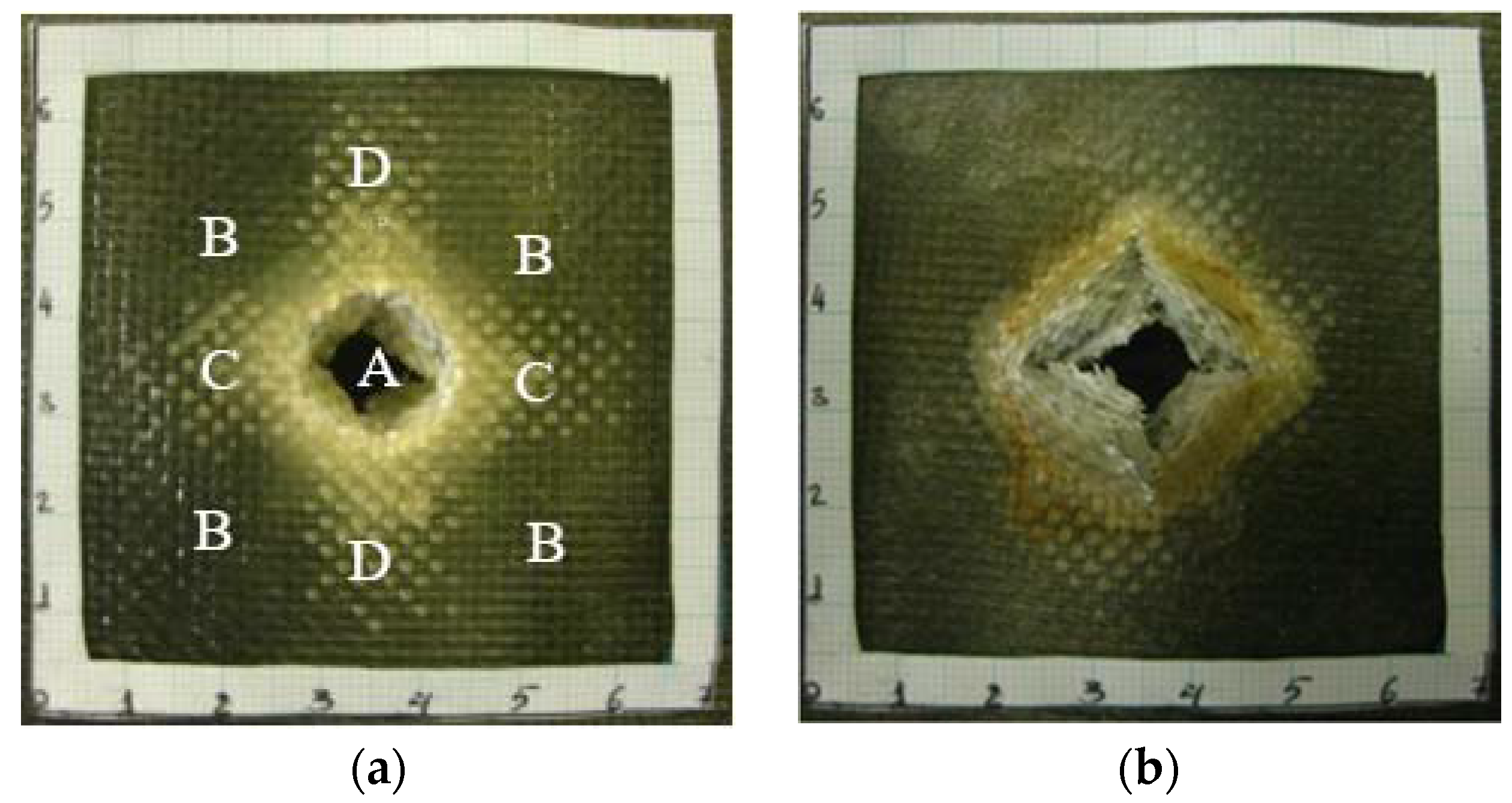
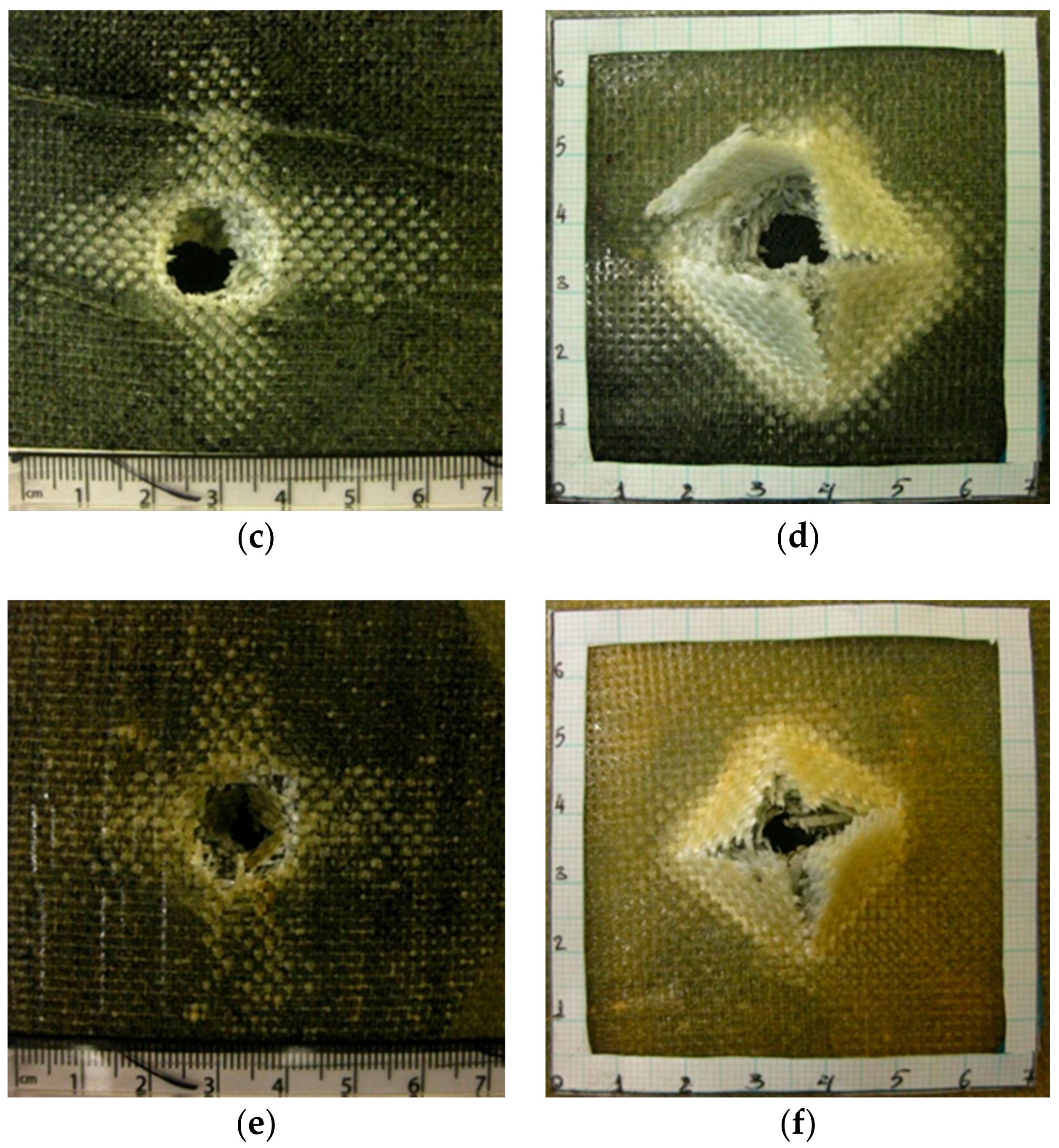
Figure 8 presents the front and back face of each damaged laminate at the end of the single impact test. The damage areas form the well-known shapes for an impacted woven fabric laminate [34], i.e., a star-like shape of the fibre break up area at the front impacted face is visible in all cases, with the points lying in the warp and weft directions, and a rhombus-like shape at the back face. The damage areas of the four main regions denote a different type of damage: The central part, A, of the damaged area represents mostly delamination, transverse fibre fracture and matrix cracking. B sections show fibre-matrix interface cracks (debonding) in both weft and warp directions. C and D sections present interface cracks (debonding) in the warp and weft directions, respectively. The relatively high impact damage resistance of woven fabric laminates is strongly linked with high inter-laminar and intra-laminar fracture resistance. The weave structure of these laminates significantly limits shear crack propagation.
Table 2 presents all the main parameters of the single impact tests of the three laminates presented in this section, where the penetration energy was the area under the load-displacement curve of the single impact for each laminate [35], calculated as the integral using the trapezoidal numerical integration rule. The damage area was measured from the photographs of Figure 8. It is demonstrated that the four interlayers of the electrospun MWNT/Araldite system in two pairs of 0/90 face-to-face interlayers (Figure 4) strengthen the laminate by increasing its peak load by 4.5%, whereas four interlayers of electrospun MWNT/Araldite/Hardener system actually result in a 6% decrease of the peak load when compared with the original 11-ply fabric-epoxy laminate. The four interlayers of the electrospun MWNT/Araldite system increase the total penetration energy by 22% and the damage area by 145%.
4. Discussion
Wide-line electrospinning was devised in this study with a new design complimenting the rotating wired drum collector of our previous work [33]: the innovation comprised a feeding device with a wide, perforated bottom line-edge over the whole length of the drum collector, aiming at achieving homogeneously distributed and aligned electrospun nanofibres across the drum wires. The electrospinning process was then optimised to coat a glass fibre fabric with a mixture of aligned MWNT-epoxy fibres and spray under 30 kV DC over a distance of 180 mm between the feed edge and the rotating drum collector. Two different types of products were electrospun: MWNT/Araldite fibres and spray in uncured form (without any hardener); and MWNT/Araldite/Hardener fibres and spray so that the MWNT/epoxy fibrous and spray coating was expected to be cured before the RTM process. In general, the presence of the low-viscosity hardener in the MWNT-epoxy solution lowered substantially the value of the solution viscosity and relaxation time, leading to the formation of a large proportion of spray rather than nano/micro-fibres; this has been attributed to the low Deborah number, De (De = Relaxation time/Process time) [36].
Assemblies of eleven fabric layers were then laid on an RTM mould, with four MWNT/epoxy coated layers, namely layer numbers 7 and 8, 10 and 11, near the face to be impacted in the impact tests. The two-layer pairs were laid so that the adjacent layers had the MWNT/epoxy fibrous and spray coatings face-to-face at 0/90 configuration for the aligned electrospun fibres. The design of the MWNT reinforcement near the face of impact was inspired by the results of Grujicic’s et al. [26] computational modelling, where it was found that placement of the MWNT interlayers near the face of impact was optimum for maximising the absorbed impact energy. Laminates were produced by RTM at a constant 2 bar inlet pressure. As expected, the presence of the two pairs of MWNT/epoxy nano-fibre/nano-particle interlayers increased the laminate thickness by about 15% (Figure 3 and Figure 5). While the glass fibre fabric-electrospun MWNT/Araldite-epoxy laminate is 3.7% heavier than the plain glass fibre fabric-epoxy laminate as expected due to the presence of the additional interlayers, the glass fibre fabric-electrospun MWNT/Araldite/hardener-epoxy laminate has actually 5.2% lower mass than the plain glass fibre fabric-epoxy laminate. The latter is attributed to the poor impregnation by the epoxy resin during RTM as is evidenced by the light colour-poor impregnated spots of the glass fibre fabric in Figure 5b compared to Figure 3 and Figure 5a, which may be due to the blocking of meso- and micro-pores by the dense deposited spray (Figure 2 (trial 12) and Figure 5b).
Single impact tests were carried out at a constant speed of a ball-shaped impactor of 2 mm/s. Load-displacement curves were obtained for both the hybrid nano-micro-composite laminates and the equivalent plain woven glass fibre fabric-epoxy laminates (micro-composite laminates). The eleven layers of the relatively thick glass fabric laminates yielded a good curve with a wide load plateau, even without the MWNTs. The hybrid laminates contained 0.15 wt% MWNTs. The configuration with the MWNT/Aradite/hardener electrospun coating, which was expected to have cured after electrospinning, was not so efficient under single impact, with lower peak load, 5% greater total penetration energy and 87% larger total damage area than the standard plain woven glass fibre fabric-epoxy laminate. The reason for this is suspected to be the large proportion of deposited spray rather than electrospun fibres in the interlayers and the resulting poor impregnation of the glass fibre fabrics by epoxy.
From the two tested configurations of hybrid laminates, the configuration with the MWNT/Araldite electrospun fibre-spray coating (without any hardener in the electrospinning) demonstrated superior behaviour with higher peak load, wider high load plateau, 22% greater total penetration energy and 145% larger total damage area than the standard plain woven glass fibre fabric-epoxy laminate. Although no hardener was added in the electrospinning, it is expected that the Araldite/hardener mixture injected during RTM impregnated and cured the MWNT coating in RTM and post-curing. It is uncertain whether the 22% increase in the penetration energy is due to the presence of the MWNT/epoxy nanofibres and particles or the increased thickness (by 15%) of the glass fibre fabric-electrospun MWNT/Araldite-epoxy laminate against the plain glass fibre fabric-epoxy laminate. Rama Subba Reddy et al. [37] reported the relation between the penetration energy, Ep (in J), and the laminate thickness, H (in mm): Ep = 10.83 H1.457 for a glass fibre-phenolic laminate, which would lead to a similar increase of absorbed energy as in this study. However, a 15% laminate thickness increase for 22% greater penetration energy would also mean a 15% increase in the mass of the glass fibre-epoxy laminate, whereas in the present study the MWNT interlayers of the glass fibre fabric-electrospun MWNT/Araldite-epoxy laminate brought only a 3.7% mass increase. It has been calculated that, in the present study, the glass fibre fabric-epoxy laminate and the glass fibre fabric-electrospun MWNT/Araldite-epoxy laminate have effected a specific energy penetration of 467.2 J/kg and 551.1 J/kg, respectively, which means that the introduction of the innovative interlayers achieved an increase of 83.9 J/kg in energy penetration, translated to 15% weight reduction in the laminate armour for an equivalent amount of energy penetration.
5. Conclusions
The present study has concluded that the addition of two pairs of electrospun 0/90 interlayers of MWNT/epoxy nanofibres/nanoparticles positioned near the impact face of an 11-ply glass fibre fabric-epoxy laminate brought significant energy absorption benefits under low rate impact. In single impact tests using a marble ball impactor of 15.6 mm diameter moving at a constant speed of 2 mm/s, this hybrid laminate exhibited an increase of 22% in the total penetration energy compared to the plain 11-ply glass fabric-epoxy laminate; this can be translated to 15% weight reduction for a hybrid laminate with the same total penetration energy as that of the plain laminate.
Author Contributions
Daniyar Sadykov and Lhadi Nouicer carried out the experimental work and wrote up the first draft of text in the form of a dissertation. Constantina Lekakou devised the project plan, supervised the research of Daniyar Sadykov and Lhadi Nouicer, fine-tuned the data analysis and put together the final form of this paper.
Conflicts of Interest
The authors declare no conflict of interest.
References
- Sandler, J.K.W.; Kirk, J.E.; Kinloch, I.A.; Shaffer, M.S.P.; Windle, A.H. Ultra-low electrical percolation threshold in carbon-nanotube-epoxy composites. Polymer 2003, 44, 5893–5899. [Google Scholar] [CrossRef]
- Moudam, O.; Andrews, T.; Lekakou, C.; Watts, J.F.; Reed, G.T. Carbon nanotube-epoxy nanocomposites: Correlation and integration of dynamic impedance, dielectric and mechanical analyses. J. Nanomater. 2013, 801850. [Google Scholar] [CrossRef]
- Rebord, G.; Hansrisuk, N.; Lindsay, B.; Lekakou, C.; Reed, G.T.; Watts, J.F. Electrofunctional nanocomposites. In Proceedings of the 2nd Electronics System-Integration Technology Conference, Greenwich, UK, 1–4 September 2008; pp. 1401–1405. [Google Scholar]
- Ogasawara, T.; Ishida, Y.; Ishikawa, T.; Yokota, R. Characterisation of multi-walled carbon nanotubes/phenylethynyl terminated polyimide composites. Compos. A Appl. Sci. Manuf. 2004, 35, 67–74. [Google Scholar] [CrossRef]
- Tai, N.H.; Yeh, M.K.; Liu, J.H. Enhancement of the mechanical properties of carbon nanotube/phenolic composites using a carbon nanotube network as the reinforcement. Carbon 2004, 42, 2774–2777. [Google Scholar] [CrossRef]
- Gojny, F.H.; Wichmann, M.H.G.; Köpke, U.; Fiedler, B.; Schulte, K. Carbon nanotube-reinforced epoxy-composites: Enhanced stiffness and fracture toughness at low nanotube content. Compos. Sci. Technol. 2004, 64, 2363–2371. [Google Scholar] [CrossRef]
- Hull, D.; Shi, Y.B. Damage mechanism characterisation in composite damage tolerance investigations. Compos. Struct. 1993, 23, 903–915. [Google Scholar] [CrossRef]
- Zhou, G.; Davies, G.A.O. Impact response of thick glass fibre reinforced polyester laminates. Int. J. Impact Eng. 1997, 17, 357–374. [Google Scholar] [CrossRef]
- Tong, L.; Mourittz, A.P.; Bannister, M.K. 3D Fiber Reinforced Composites; Elsevier: Boston, MA, USA, 2002; pp. 1–12. ISBN 9780080439389. [Google Scholar]
- Hojo, M.; Ando, T.; Tanaka, M.; Adachi, T.; Ochiai, S.; Endo, Y. Modes I and II interlaminar fracture toughness and fatigue delamination of CF/epoxy laminates with self-same epoxy interleaf. Int. J. Fatigue 2006, 28, 1154–1165. [Google Scholar] [CrossRef]
- Tsantzalis, S.; Karapappas, P.; Vavouliotis, A.; Tsotra, P.; Kostopoulos, V.; Tanimoto, T.; Friedrich, K. On the improvement of toughness of CFRPs with resin doped with CNF and PZT particles. Compos. A Appl. Sci. Manuf. 2007, 38, 1159–1162. [Google Scholar] [CrossRef]
- Iqbal, K.; Khan, S.U.; Munir, A.; Kim, J.K. Impact damage resistance of CFRP with nanoclay-filled epoxy matrix. Compos. Sci. Technol. 2009, 69, 1949–1957. [Google Scholar] [CrossRef]
- Khan, S.U.; Iqbal, K.; Munir, A.; Kim, J.K. Quasi-static and impact fracture behaviors of CFRPs with nanoclay-filled epoxy matrix. Compos. A Appl. Sci. Manuf. 2011, 42, 253–264. [Google Scholar] [CrossRef]
- Siddiqui, N.A.; Woo, R.S.C.; Kim, J.K.; Leung, C.C.K.; Munir, A. Mode I interlaminar fracture behaviour and mechanical properties of CFRPs with nanoclay-filled epoxy matrix. Compos. A Appl. Sci. Manuf. 2007, 38, 449–460. [Google Scholar] [CrossRef]
- Hsieh, T.H.; Kinloch, A.J.; Taylor, A.C.; Sprenger, S. The effect of silica nanoparticles and carbon nanotubes on the toughness of a thermosetting epoxy polymer. J. Appl. Polym. Sci. 2011, 119, 2135–2142. [Google Scholar] [CrossRef]
- Mohanty, A.K.; Wibowo, A.; Misra, M.; Drzal, L.T. Development of renewable resource-based cellulose acetate bioplastic: Effect of process engineering on the performance of cellulosic plastics. Polym. Eng. Sci. 2003, 43, 1151–1161. [Google Scholar] [CrossRef]
- Choi, J.S.; Lim, S.T.; Choi, H.J.; Hong, S.M.; Mohanty, A.K.; Drzal, L.T.; Misra, M.; Wibowo, A.C. Rheological, thermal, and morphological characteristics of plasticized cellulose acetate composite with natural fibers. Macromol. Symp. 2005, 224, 297–307. [Google Scholar] [CrossRef]
- Rahimzadeh, T.; Arruda, E.M.; Thouless, M.D. Design of armor for protection against blast and impact. J. Mech. Phys. Solids 2015, 85, 98–111. [Google Scholar] [CrossRef]
- Ma, P.; Kim, J. Carbon Nanotubes for Polymer Reinforcement; Taylor & Francis Group: Boca Raton, FL, USA, 2011; ISBN 9781439826269. [Google Scholar]
- Khan, S.U.; Kim, J.K. Impact and delamination failure of multiscale carbon nanotube-fiber reinforced polymer composites: A review. Int. J. Aeronaut. Space Sci. 2011, 12, 115–133. [Google Scholar] [CrossRef]
- Lekakou, C.; Kontodimopoulos, I.; Murugesh, A.K.; Jesson, D.A.; Watts, J.; Smith, P.A. Processability studies of silica-thermoset polymer matrix nanocomposites. Polym. Eng. Sci. 2008, 48, 216–222. [Google Scholar] [CrossRef] [Green Version]
- Karapappas, P.; Vavouliotis, A.; Tsotra, P.; Kostopoulos, V.; Paipetis, A. Enhanced fracture properties of carbon reinforced composites by the addition of multi-wall carbon nanotubes. J. Compos. Mater. 2009, 43, 977–985. [Google Scholar] [CrossRef]
- Kostopoulos, V.; Baltopoulos, A.; Karapappas, P.; Vavouliotis, A.; Paipetis, A. Impact and after-impact properties of carbon fibre reinforced composites enhanced with multi-wall carbon nanotubes. Compos. Sci. Technol. 2010, 70, 553–563. [Google Scholar] [CrossRef]
- Inam, F.; Wong, D.W.Y.; Kuwata, M.; Peijs, T. Multiscale hybrid micro-nanocomposites based on carbon nanotubes and carbon fibers. J. Nanomater. 2010, 453420. [Google Scholar] [CrossRef]
- Wan Hanif, W.Y.; Risby, M.S.; Noor, M.M. Influence of carbon nanotube inclusion on the fracture toughness and ballistic resistance of twaron/epoxy composite panels. Procedia Eng. 2015, 114, 118–123. [Google Scholar] [CrossRef]
- Grujicic, M.; Pandurangan, B.; Koudela, K.L.; Cheeseman, B.A. Ballistic-performance optimization of a hybrid carbon-nanotube/E-glass reinforced poly-vinyl-ester-epoxy-matrix composite armor. Appl. Surf. Sci. 2007, 42, 5347–5359. [Google Scholar] [CrossRef]
- Zhao, X.; Koos, A.A.; Chu, B.T.T.; Johnston, C.; Grobert, N.; Grant, P.S. Spray deposited fluoropolymer/multi-walled carbon nanotube composite films with high dielectric permittivity at low percolation threshold. Carbon 2008, 47, 561–569. [Google Scholar] [CrossRef]
- Palazzetti, R. Electrospun Nanofibrous Interleaves in Composite Laminate Materials. Ph.D. Thesis, University of Bologna, Bologna, Italy, 2012. [Google Scholar]
- Shenoy, S.L.; Bates, W.D.; Frisch, H.L.; Wnek, G.E. Role of chain entanglements on fiber formation during electrospinning of polymer solutions: Good solvent, non-specific polymer-polymer interaction limit. Polymer 2005, 46, 3372–3384. [Google Scholar] [CrossRef]
- Zhong, X.; Kim, K.; Fang, D.; Ran, S.; Hsiao, B.S.; Chu, B. Structure and process relationship of electrospun bioabsorbable nanofiber membranes. Polymer 2002, 43, 4403–4412. [Google Scholar] [CrossRef]
- Saunders, R.A.; Lekakou, C.; Bader, M.G. Compression in the processing of polymer composites 1. A mechanical and microstructural study for different glass fabrics and resins. Compos. Sci. Technol. 1999, 59, 983–993. [Google Scholar] [CrossRef]
- Liu, L.; Liang, Y.; Xu, G.; Zhang, H.; Huang, Z.M. Mode I interlaminar fracture of composite laminates incorporating with ultrathin fibrous sheets. J. Reinf. Plast. Compos. 2008, 27, 1147–1162. [Google Scholar] [CrossRef]
- Salifu, A.A.; Nury, B.D.; Lekakou, C. Electrospinning of nanocomposite fibrillar tubular and flat scaffolds with controlled fiber orientation. Ann. Biomed. Eng. 2011, 39, 2510–2520. [Google Scholar] [CrossRef] [PubMed] [Green Version]
- Hirai, Y.; Hiroyuki, H.; Kim, J.K. Damage modes in impact loading of glass woven fabric composites. Adv. Compos. Lett. 1996, 5, 56–60. [Google Scholar]
- Belingardi, G.; Vadori, R. Low velocity impact tests of laminate glass-fiber-epoxy matrix composite material plates. Int J. Impact Eng. 2002, 27, 213–229. [Google Scholar] [CrossRef]
- Lekakou, C.; Wilson, P.; Craggs, D.; Chau, Y.C.; Salifu, A.A.; Chen, Y.L.; Watts, J.F. Electrospinning of polymer nanocomposites. In Proceedings of the 17th International Conference on Composite Materials, Edinburgh, UK, 27–31 July 2009. [Google Scholar]
- Rama Subba Reddy, P.; Sreekantha Reddy, T.; Madhu, V.; Gogia, A.; Venkateswara Rao, K. Behavior of E-glass composite laminates under ballistic impact. Mater. Des. 2015, 84, 79–86. [Google Scholar] [CrossRef]
Figure 1.
Schematic of the electrospinning apparatus.
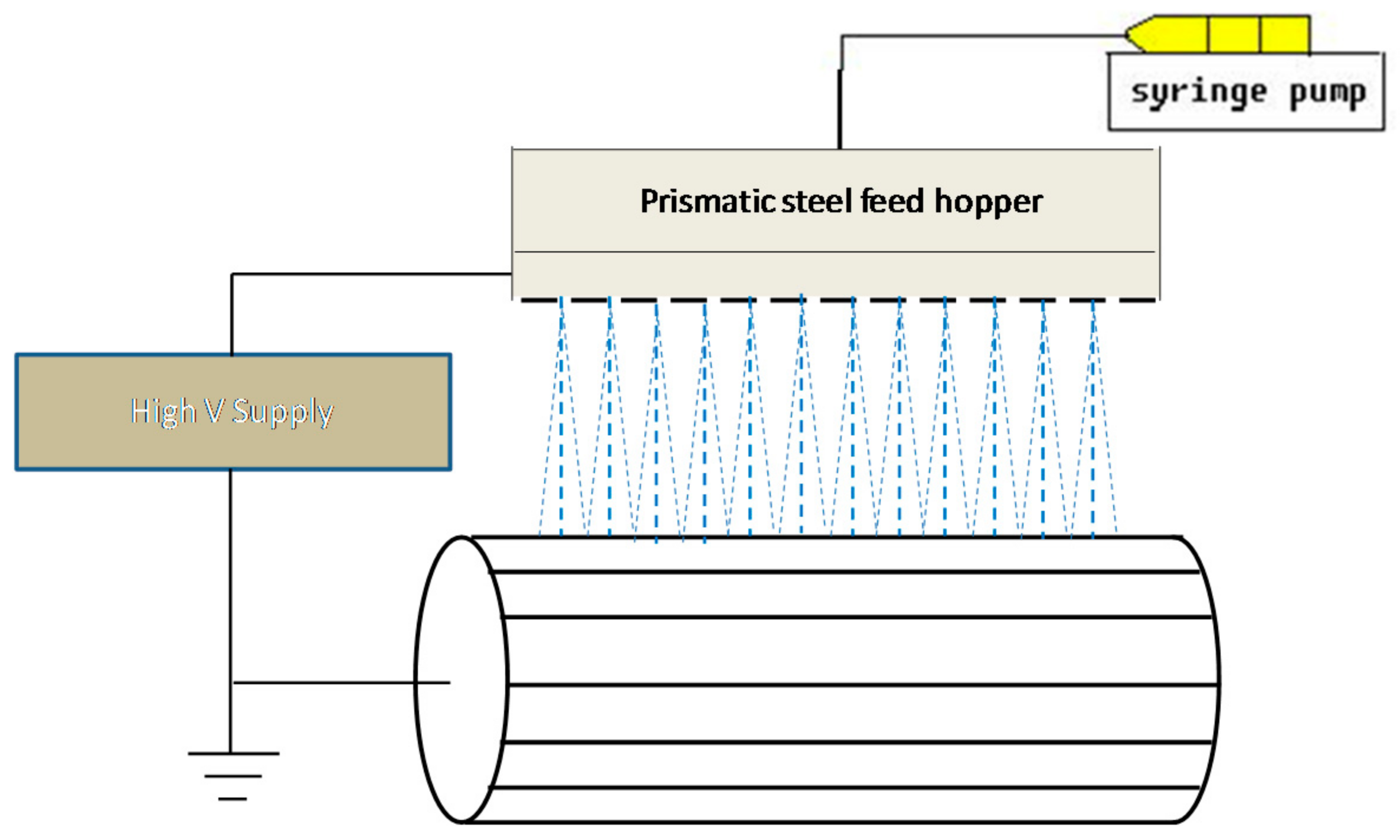
Figure 2.
Optical micrographs of electrospun products in trials 5 and 9, and trial 12 of Table 1.
Figure 2.
Optical micrographs of electrospun products in trials 5 and 9, and trial 12 of Table 1.


Figure 3.
Thickness measurements of the 11-ply plain weave glass fibre fabric-epoxy laminate disc used in the impact test; laminate disc mass: 134 ± 2 g.
Figure 3.
Thickness measurements of the 11-ply plain weave glass fibre fabric-epoxy laminate disc used in the impact test; laminate disc mass: 134 ± 2 g.
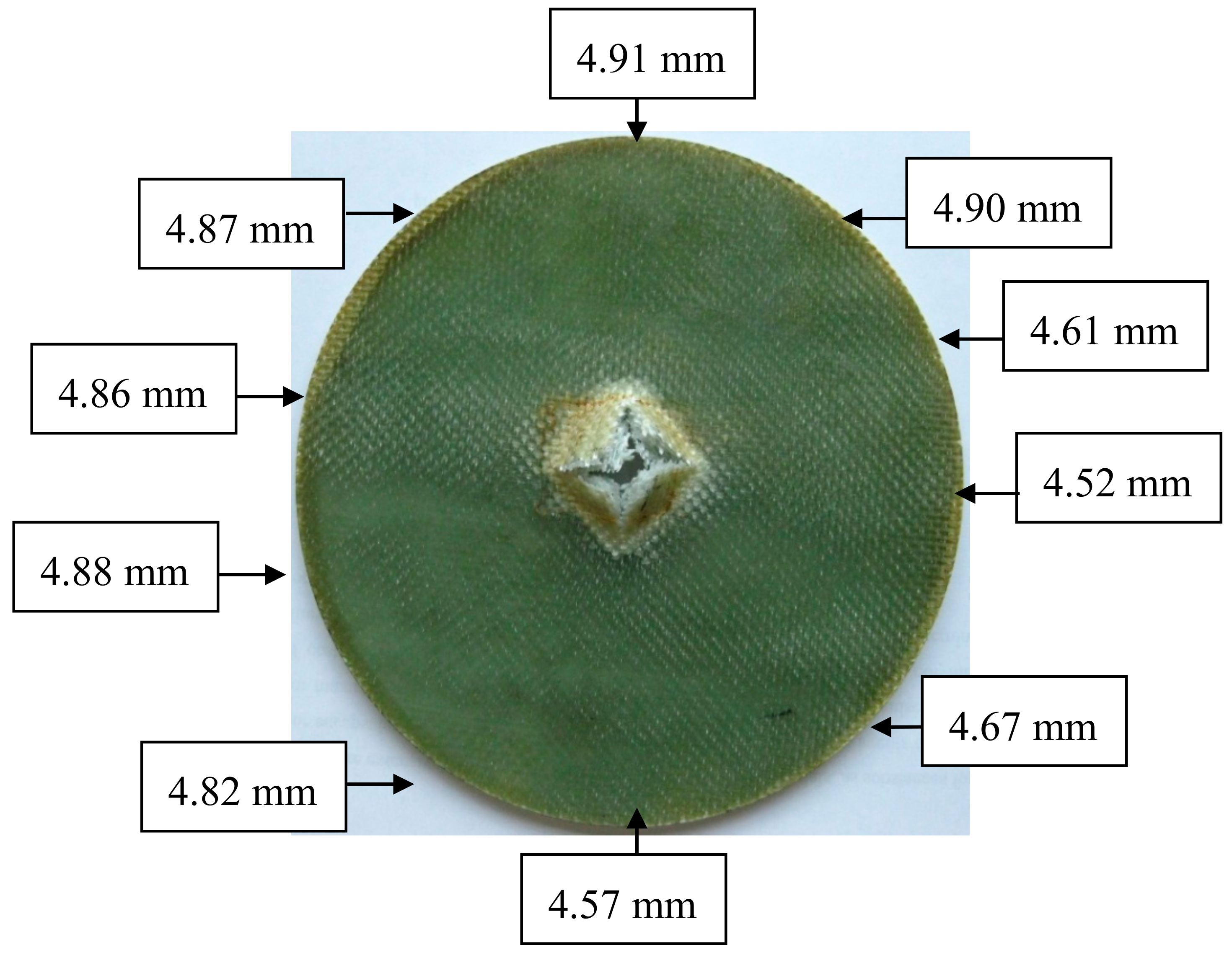
Figure 4.
Diagram of the ply assembly in the hybrid plain glass fibre fabric-multi-walled carbon nanotube (MWNT)-epoxy laminates.
Figure 4.
Diagram of the ply assembly in the hybrid plain glass fibre fabric-multi-walled carbon nanotube (MWNT)-epoxy laminates.

Figure 5.
Thickness distribution of the hybrid plain glass fibre fabric-MWNT-epoxy laminates; (a) laminate disc mass: 139 ± 2 g, (b) laminate disc mass: 127 ± 3 g.
Figure 5.
Thickness distribution of the hybrid plain glass fibre fabric-MWNT-epoxy laminates; (a) laminate disc mass: 139 ± 2 g, (b) laminate disc mass: 127 ± 3 g.

Figure 6.
Load-displacement plots of the single impact tests at a constant speed of the impactor at 2 mm/s. Tests were repeated three times with different laminates for each type of material: maximum error in the maximum load = ± 3%.
Figure 6.
Load-displacement plots of the single impact tests at a constant speed of the impactor at 2 mm/s. Tests were repeated three times with different laminates for each type of material: maximum error in the maximum load = ± 3%.

Figure 7.
A comparison of the load-displacement curves of the plain woven glass fibre fabric-epoxy laminate and the hybrid plain woven glass fibre fabric-electrospun MWNT/Araldite-epoxy laminate.
Figure 7.
A comparison of the load-displacement curves of the plain woven glass fibre fabric-epoxy laminate and the hybrid plain woven glass fibre fabric-electrospun MWNT/Araldite-epoxy laminate.
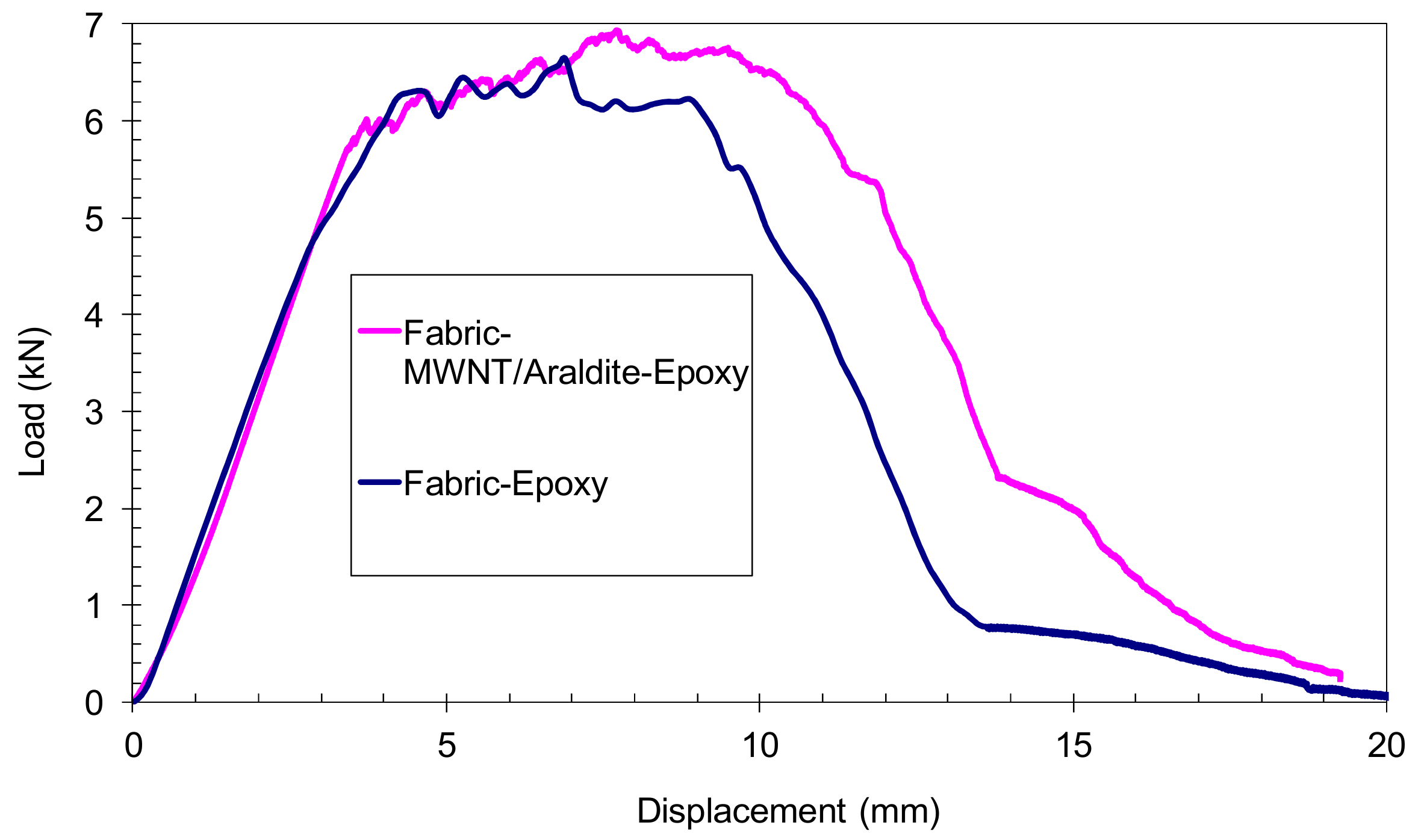
Figure 8.
Laminate damage areas at the front and back face: 11-ply plain woven glass fibre fabric-epoxy laminate: (a) front face and (b) back face; 11-ply plain woven glass fibre fabric-MWNT/Araldite-epoxy laminate: (c) front face and (d) back face; 11-ply plain woven glass fibre fabric-MWNT/Araldite/hardener-epoxy laminate: (e) front face and (f) back face.


Table 1.
Material composition, processing parameters and results of the electrospinning of carbon nanotube (CNT)-epoxy.
Table 1.
Material composition, processing parameters and results of the electrospinning of carbon nanotube (CNT)-epoxy.
| Number of Trial | Material composition (mL) | Flow rate (mL/hr) | Duration (min) | Microstructure description | ||
|---|---|---|---|---|---|---|
| MWNT solution | Araldite | Hardener | ||||
| 1 | 10 | 1.695 | 0.805 | 27 | 10 | Spray only |
| 2 | 10 | 10 | 3.5 | 27 | 15 | Big droplets and few nanofibres |
| 3 | 10 | 30 Epoxy 300 | 18.38 g MNA & 1.2 g K61 | 4 | 30 | Mostly fine spray and some big drops |
| 4 | 10 | 20 | - | 4 | 10 | Thick microfibres, small spray and big droplets |
| 5 | 10 | 10 | - | 4 | 10 | Fine spray, high concentration of nanofibres and some droplets |
| 6 | 5 | 7 | - | 4 | 15 | Spray and big islands. No nanofibres |
| 7 | 5 | 6 | - | 4 | 15 | Spray and small concentration of nanofibres |
| 8 | 5 | 2.5 | - | 4 | 15 | Some drops and small concentration of nanofibres |
| 9 | 10 | 10 | - | 4 | 10 | Some islands and high concentration of nanofibres |
| 10 | 5 | 5 | 1.5 | 4 | 5 | Big drops, some spray and low concentration of nanofibres |
| 11 | 5 | 8 | 2.8 | 4 | 5 | Fine spray and no nanofibres |
| 12 | 5 | 5.5 | 1.925 | 4 | 5 | Mostly fine spray and medium concentration of nanofibres |
Table 2.
Single impact test parameters for the three types of tested 11-ply laminates.
| Laminates | Peak Load (kN) | Total Penetration Energy (J) | Real Damage Area (mm2) |
|---|---|---|---|
| Fabric-Epoxy | 6.6 ± 0.1 | 62.6 ± 2.4 | 1722 |
| Fabric-MWNT/Araldite/Hardener-Epoxy | 6.2 ± 0.2 | 65.8 ± 3.0 | 3215 |
| Fabric-MWNT/Araldite-Epoxy | 6.9 ± 0.1 | 76.6 ± 2.5 | 4225 |
© 2017 by the authors. Licensee MDPI, Basel, Switzerland. This article is an open access article distributed under the terms and conditions of the Creative Commons Attribution (CC BY) license (http://creativecommons.org/licenses/by/4.0/).
Share and Cite
MDPI and ACS Style
Sadykov, D.; Nouicer, L.; Lekakou, C. Hybrid Woven Glass Fibre Fabric-Multi-Walled Carbon Nanotube-Epoxy Composites Under Low Rate Impact. J. Compos. Sci. 2017, 1, 10. https://doi.org/10.3390/jcs1010010
AMA Style
Sadykov D, Nouicer L, Lekakou C. Hybrid Woven Glass Fibre Fabric-Multi-Walled Carbon Nanotube-Epoxy Composites Under Low Rate Impact. Journal of Composites Science. 2017; 1(1):10. https://doi.org/10.3390/jcs1010010
Chicago/Turabian StyleSadykov, Daniyar, Lhadi Nouicer, and Constantina Lekakou. 2017. "Hybrid Woven Glass Fibre Fabric-Multi-Walled Carbon Nanotube-Epoxy Composites Under Low Rate Impact" Journal of Composites Science 1, no. 1: 10. https://doi.org/10.3390/jcs1010010