Parameter Study and Method for Processing an Adhesion Promoter for Manufacturing Sandwich Sheets

1
Kirchhoff Automotive Deutschland GmbH Am Eckenbach 10-14, 57439 Attendorn, Germany
2
Chair of Forming Technology, University Siegen, Paul-Bonatz-Straße 9-11, 57076 Siegen, Germany
*
Author to whom correspondence should be addressed.
J. Compos. Sci. 2017, 1(1), 5; https://doi.org/10.3390/jcs1010005
Submission received: 6 June 2017
/
Revised: 25 June 2017
/
Accepted: 26 June 2017
/
Published: 28 June 2017
Abstract
:Next to the electrification of the powertrain, lightweight design plays an important role in automotive industry. Within the last few years an increasing amount of new materials have been used in automotive structures. One type belonging to this new generation of materials is sandwich materials with sheet metal cover sheets and an inner thermoplastic core. The link between the metallic sheet and the thermoplastic core is achieved with the use of an interface layer made of an adhesion promoter. In the present research, the polyamide 6 based adhesion promoter Evonik Hylink was used. To analyze the thermal behavior of the adhesion promoter a DSC analysis was performed. Based on the DSC analysis, a process window is established and verified by mechanical tests. Furthermore, the mechanical properties of the adhesion promoter are characterized with single lap shear tests in dependence to different process parameters temperature, compression time and layer thickness. With the presented method, a process window for processing the adhesion promoter can be established in relation to the varied parameters.
1. Introduction
With the increasing demand for reduction in pollutant emissions and the growing importance of electric mobility, lightweight construction plays a key role in the automotive industry. One approach for the realization of lighter body concepts is the use of sandwich panels [1]. In addition to an increase in stiffness and strength in the vehicle structure, sandwich plates are contributing to increase driving comfort due to their damping properties. The considered materials generally consist of metallic cover layers with a polymeric core layer, which may also be fiber-reinforced (Figure 1). The bonding of the core layer to the metallic cover layer is usually effected by the use of an adhesion promoter [2].
The forming behavior and the failure mechanisms, like delamination, in dependence of the process parameters were investigated in [3]. In [4], the relevance of the forming temperature was pointed out. The delamination of acoustic damping sandwich sheets was in [5] observed. The formability of commercial sandwich materials with a viscoelastic core was characterized by lap shear tests with a focus on the bending behavior. In [6], it was pointed out that the failure of sandwich materials in the forming process is shear based and mainly occurs in the metal/adhesive interface.
Further previous studies mainly dealt with the deep drawing and stretch-forming of sandwich sheets [7] and its failure in general via different failure mechanisms was discussed [8].
In [9], the manufacturing and processing of sandwich sheets with an epoxy adhesion promoter was described. Sheets with a polymeric core layer were tested regarding peel resistance and deep drawing behavior. A characterization of thermoplastic adhesion promoters was carried out in [10]. The authors performed lap shear tests with thin cover sheets. The lap shear tests pointed out the effect of temperature on the existent joint. The process parameters for the consolidation of the sheets were not described.
The mechanical properties of the adhesion promoter layer are usually characterized by injection molding. A precoated steel blank is inserted in the injection molding tool and the thermoplastic is molded onto the blank [11]. Due to the low stiffness of the thermoplastic, a higher deformation of the base material of the lap shear specimen occurs compared to lap shear specimens made of steel.
In order to understand all of the influences on the forming process of sandwich sheets it is necessary to consider the manufacturing process. Within this investigation, the influence of the manufacturing parameter time, layer thickness, and temperature on the adhesion promoter between the core and the outer steel layers are pointed out. As an adhesion promoter, a copolyamid-based system is used. To obtain the behavior of the adhesion promoter, sandwich specimens with a thin core layer just containing adhesion promoter are manufactured in a pressing process and tested afterwards.
The main focus is on the shear tensile test and the shear strength of the interface layer. For this reason, the sandwich sheet is reduced to the two cover layers and the adhesion promoter inner layer. In the first step, the adhesion promoter coated steel blanks are consolidated to a single lap shear specimen by using a heated tool setup in a universal testing machine. Afterwards, the specimens are tested in the testing machine. During the consolidation phase, the temperature, compression time, and layer thickness parameters of the adhesion promoter are varied.
2. Design of Tests and Preparing Work
2.1. Materials
Base material steel blanks made of CR340LA with a thickness of sb = 2.5 mm are used. In order to improve the adhesion of the bonding agent to the metal surface, an iron phosphating coating was provided before applying the adhesion promoter [12].
To represent the adhesive inner layer, the crosslinkable adhesion promoter Evonik Hylink is used [13]. This adhesion promoter is delivered as powder and is applied by powder coating or in a scattering process. For the presented specimens, a powder coating process was used. After powder coating, the specimen was burnt in at 200 °C for 5 min in a chamber furnace. The thickness of the resulting adhesion promoter layer sap is in a range between 120 and 150 µm.
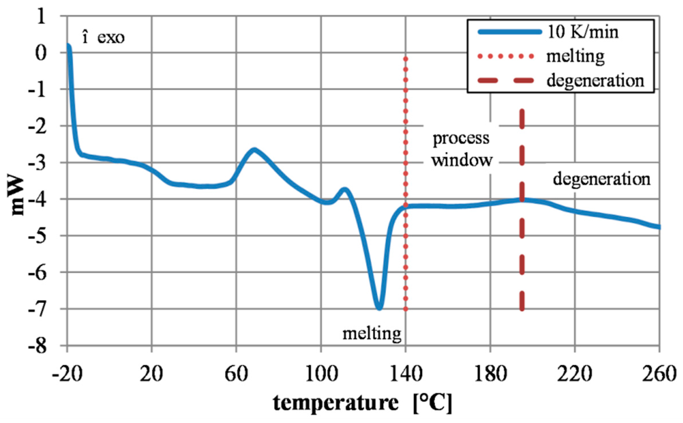
For the first determination of a temperature window for processing the coated blanks to shear lap specimens, the pure adhesion promoter powder was introduced to a differential scanning calorimetry (DSC) analysis. The analysis was performed with a Mettler Toledo DSC30. In order to represent the influence of the temperature during the production of sandwich in the DSC, a two-fold heating in the DSC is necessary (Figure 2). The first heating cycle represents the burning-in process of the adhesion promoter after application to the sheet metal. During the second temperature cycle, which is shown in Figure 3, the precoated sheets are consolidated to a sandwich sheet or in this case to a shear specimen.
The heating and cooling rate in the experiment was set to 10 K/min. The DSC analyses show an endothermic peak at a temperature of 135 °C (Figure 3), which is characteristic for the melting of the adhesion promoter [14]. The end of the melting peak at 140 °C determines the beginning of the relevant temperature range for consolidating the single sheets to the test specimen. Furthermore, the DSC analysis gives a first reference point for the upper temperature limit. At a temperature of 195 °C, the decomposition of the adhesion promoter begins. This is characterized by the descending line in an endothermic direction.
2.2. Preparation
At first, the test specimens are prepared. As a base material, sheet blanks made of CR340LA with a thickness of sb = 2.5 mm are used. Afterwards, the steel blanks were coated with the adhesion promoter Evonik Hylink.
To perform single lap shear tests, the coated blanks are wet separated in order to minimize deformation on the cutting edges which can influence the mechanical properties. Afterwards, two sheets are pre-fixed and then bonded to a sandwich with an adhesive interlayer under pressure and temperature. An overlap length for the shear tensile specimens of ll = 20 mm was set in advance (Figure 6a). The sample width was set to lw = 25 mm. In order to achieve pure shear stress in the adhesion-promoting layer, FE simulations of the shear tensile test with an assumed shear strength of 25 MPa were carried out before. Based on the simulations, a sufficient sheet thickness of the base material CR340LA was defined in order to reduce deformation by the bending moment occurring in the lap shear tensile test [15]. Furthermore, compensation sheets were inserted in the clamping area of the tensile machine to consider the offset in the specimen geometry. By preventing the deformation, the peel stress on the core layer is minimized.
2.3. Consolidation
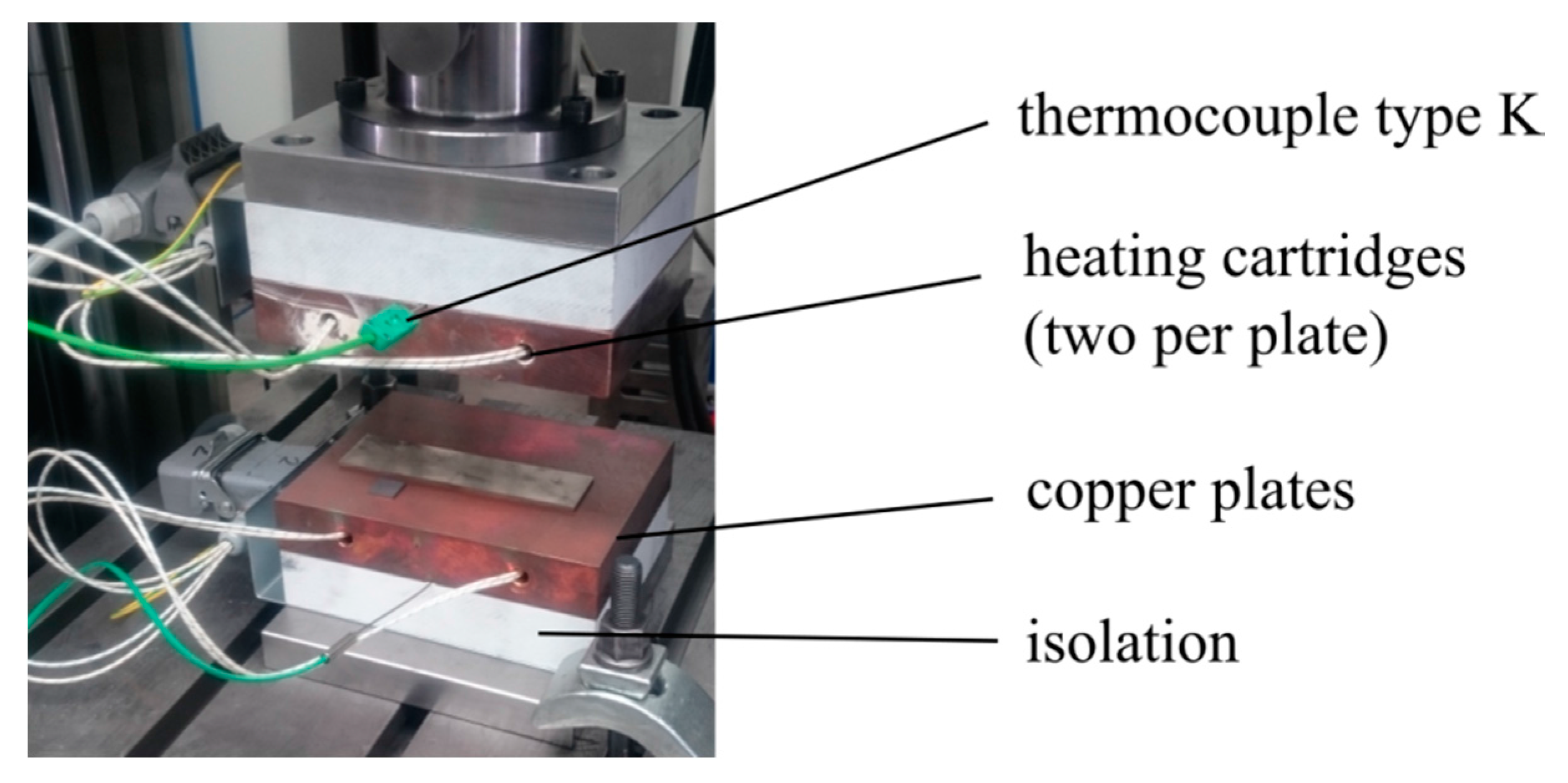
The single blanks are consolidated to a sandwich composite by using an electrically heated plate tool (Figure 4) which is attached to a Zwick/Roell Z250 universal testing machine (Zwick GmbH & Co. KG, Ulm, Germany). The working surfaces of the tool are made of copper to ensure a homogeneous temperature distribution in the tooling setup.
Besides the temperature, the compression time for consolidation and the layer thickness of the core were varied (Table 1). For the compression time tc values between 30 and 180 s are assumed. The layer thickness sap, which is reached during the compression, was adjusted in the test setup with spacers between the upper and lower tool.
Figure 5 shows a representative force and temperature curve in relation to the consolidation time which was measured during the consolidation process. To ensure that the desired temperature in the adhesive promoter layer is reached, the temperature in the adhesive promoter core was measured during the consolidation process of the lap shear specimens with a thin film thermocouple. In the range from −30 s till 0 s, the specimen is placed on the lower tool and the punch still has no contact. After the first contact of the punch, the heating rate increases and the target temperature of 170 °C in the core was reached after 30 s. The compression time starts as the set force of 2000 N is reached. During the compression time, the temperature is held constant to achieve a proper consolidation between the sheets. A maximum delta of 5 °C between the adjusted temperature of the tool and core temperature was measured. During the whole compression time, the force is controlled by the testing machine at a constant value of 2000 N.
After consolidation, the test specimens are left to cool down at room temperature. Afterwards, the dimensions were measured and the specimens were tested in a shear tensile test.
3. Results of Single Lap Shear Tests and Discussion
For the characterization of the prepared composites and for the evaluation of the influence of the varied parameters of temperature, time, and layer thickness, the specimens were tested with the universal testing machine in a shear tensile test in accordance to DIN EN 1465 [16]. The test speed was set to v = 0.025 mm/s and was controlled by a local displacement transducer with an initial measurement length of lini = 30 mm.
In the first series of experiments, the temperature was varied and the compression time and the layer thickness resulting from the distancing were kept constant. For evaluating the shear tensile tests, the shear strength τmax as well as the shear strain γgl were used (Figure 6b).
3.1. Variation of Compression Temperature
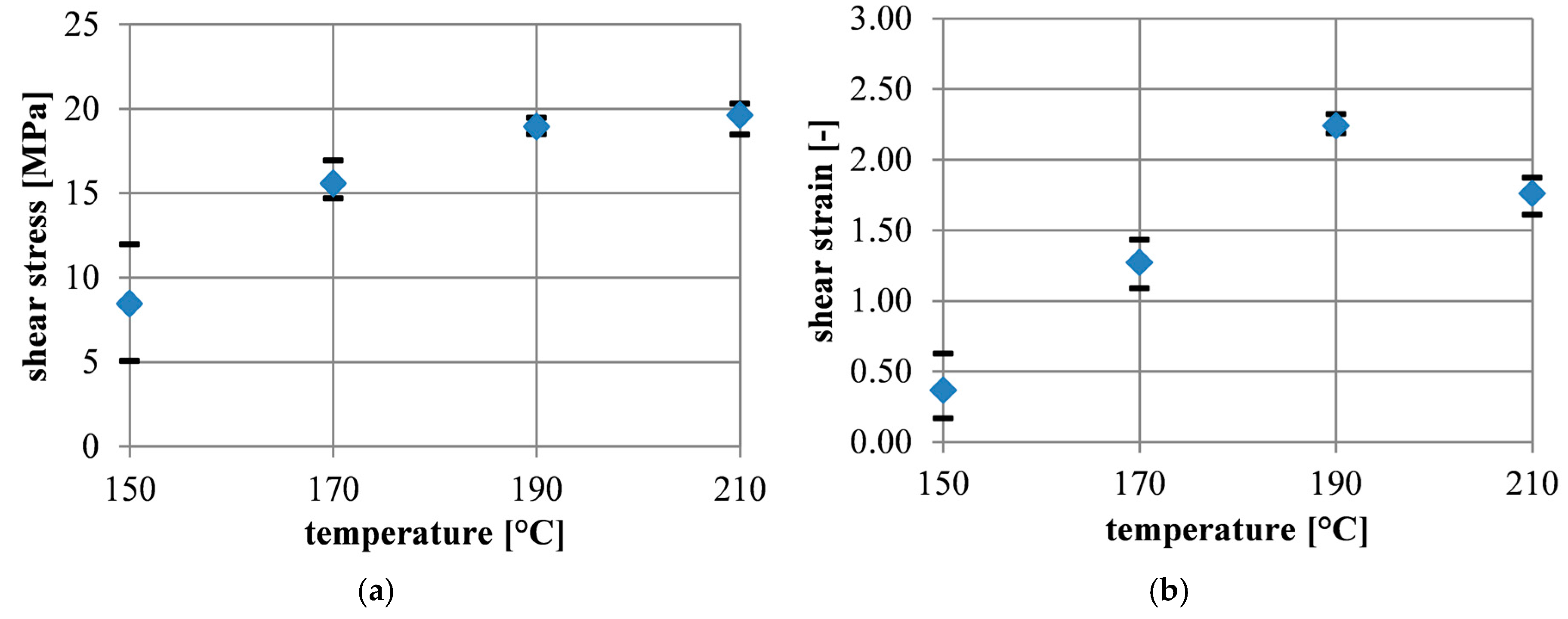
In the first series of experiments, the temperature was varied while the compression time tc and the layer thickness sap were kept constant. The shear tensile tests show that the shear strength τmax and the shear strain γm increase at temperatures up to 190 °C (Figure 7). The maximum average shear stress was τmax = 18.9 MPa and the maximum average shear strain γm = 2.24. In addition to the increase of the shear strength and the shear strain, the spread between the samples of the same parameter set decreases as the temperature rises to 190 °C. When the temperature rises above the decomposition temperature, the shear strength remains almost the same. However, there is a decrease in the maximum shear strain. In [17], an epoxy resin was analyzed in a lap shear test. The interface strength was set in relation to the curing temperature. A similar trend for the shear stress was observed. Next, to the shear stress the work was monitored, which shows a similar trend as Figure 7b. Due to the definition of the physical work, W = F × s, the measured strain is proportional to the work. The reduction of shear strain is accurate to embrittlement of the polymer layer [17]. which is accurate to signs for thermal degradation [18].
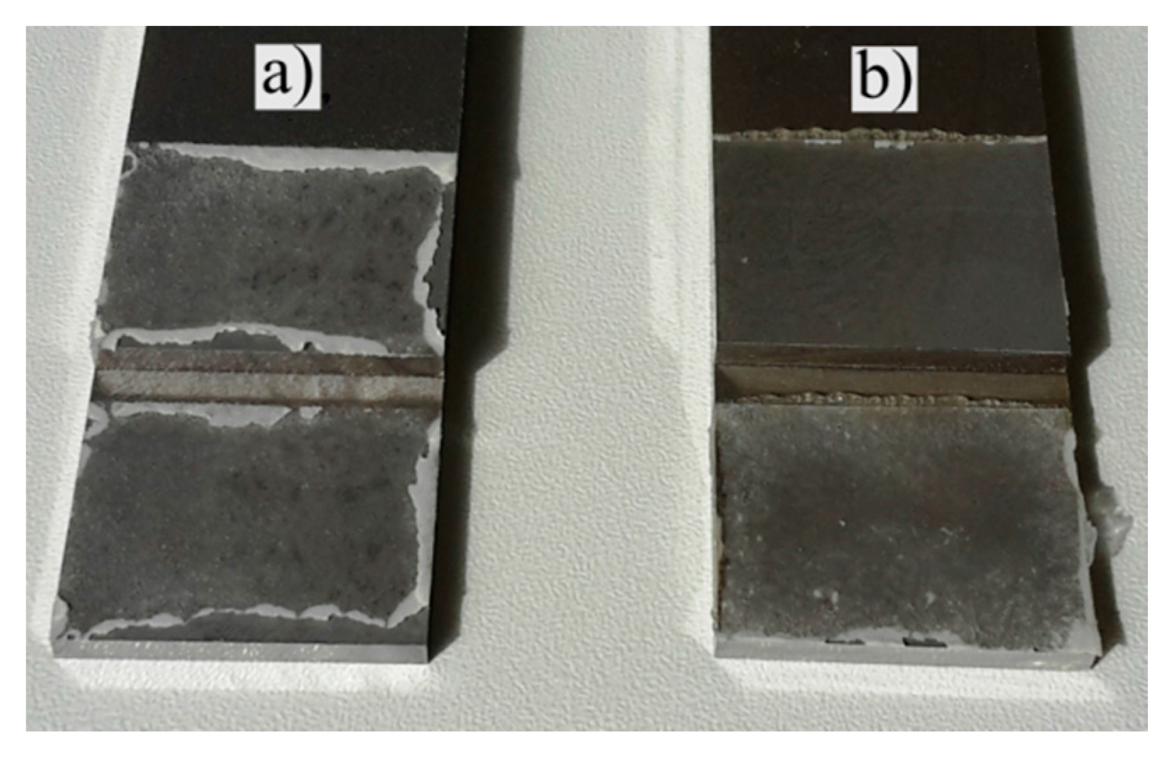
At a temperature of 150 °C and below, a sufficient connection between the two coated steel sheets cannot be achieved. When the maximum stress is reached at an average of 8.4 MPa, fracture occurs in the still existing interface between the two bonding agent layers (Figure 8). On the contrary, at higher temperatures, adhesive failure occurs in the interface between steel substrate and adhesion promoter.
3.2. Variation of Compression Time
As a further parameter in the sample preparation, the compression time was varied while maintaining the temperature at 190 °C and the layer thickness at 0.16 mm. The maximum average shear strength of 19.8 MPa and the maximum average shear strain of 2.24 occurs at 90 s compression time. Furthermore, the lowest spread is obtained at 90 s compression time (Figure 9). At 30 s and 180 s, the average shear strength and shear strain are lower. In addition to this, a decrease in strength down to 17.1 MPa and a reduced maximum shear strain down to 1.55 is obtained. At a compression time of 180 s, a slight discoloration of the adhesion promoter is already visible, which indicates an initial decomposition with increasing holding time. As mentioned by [19], typical indications of a decomposition are a reduced ductility and embrittlement as well as a change of color. The embrittlement is evident through the reduction of shear strain at 180 s compression time.
3.3. Variation of Core Thickness
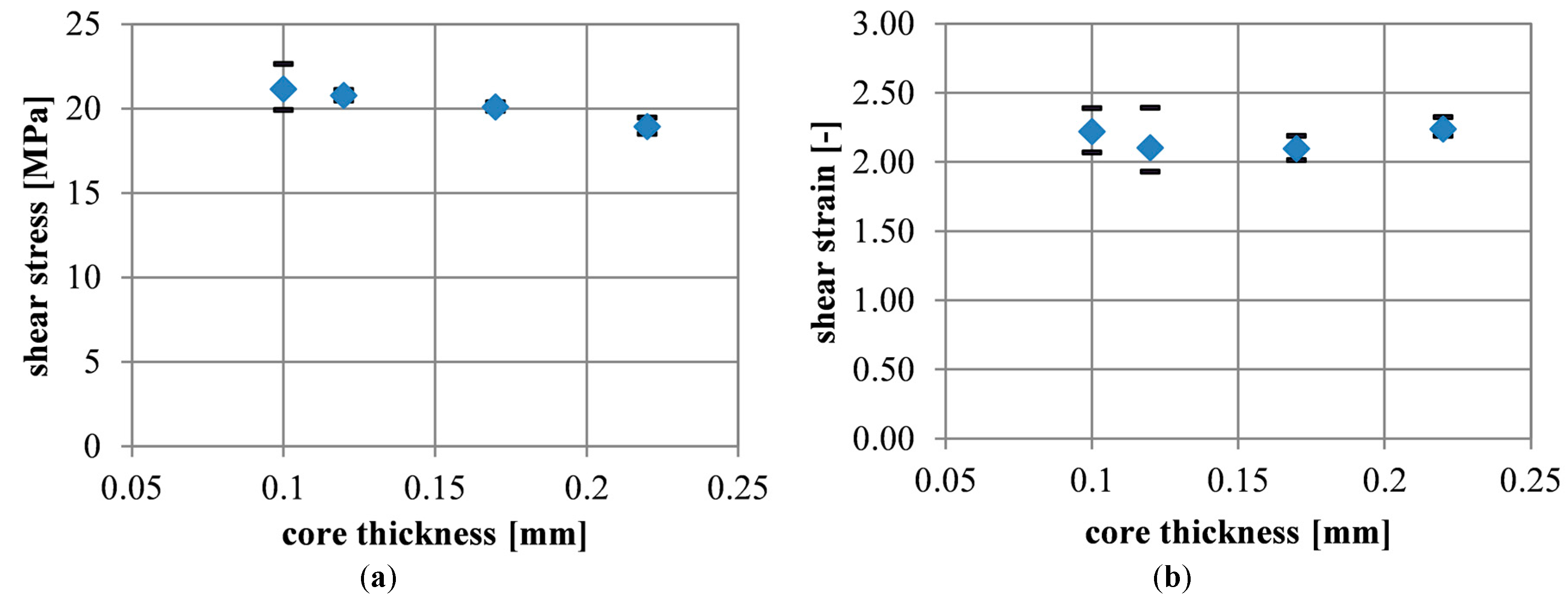
In the next series of experiments, the thickness of the adhesion promoter was varied while the temperature was remained constant at 190 °C and the compression time at 90 s. As (Figure 10a) and (Figure 11) are showing the layer thickness increases as the strength decreases from an average of 21.15 MPa down to an average of 18.9 MPa. The average values and the standard deviation s can be obtained from Table 2. Similar results were also obtained for epoxy adhesives [6,20,21]. According to [6], this can be caused by interface stresses between the adhesion promoter and the steel blank. In [15], it is mentioned that the reduction of shear strength with increasing adhesive layer thickness is a result of the interference of the lateral contraction. A thick adhesive layer does not interfere with the lateral contraction as much as a thin adhesive layer.
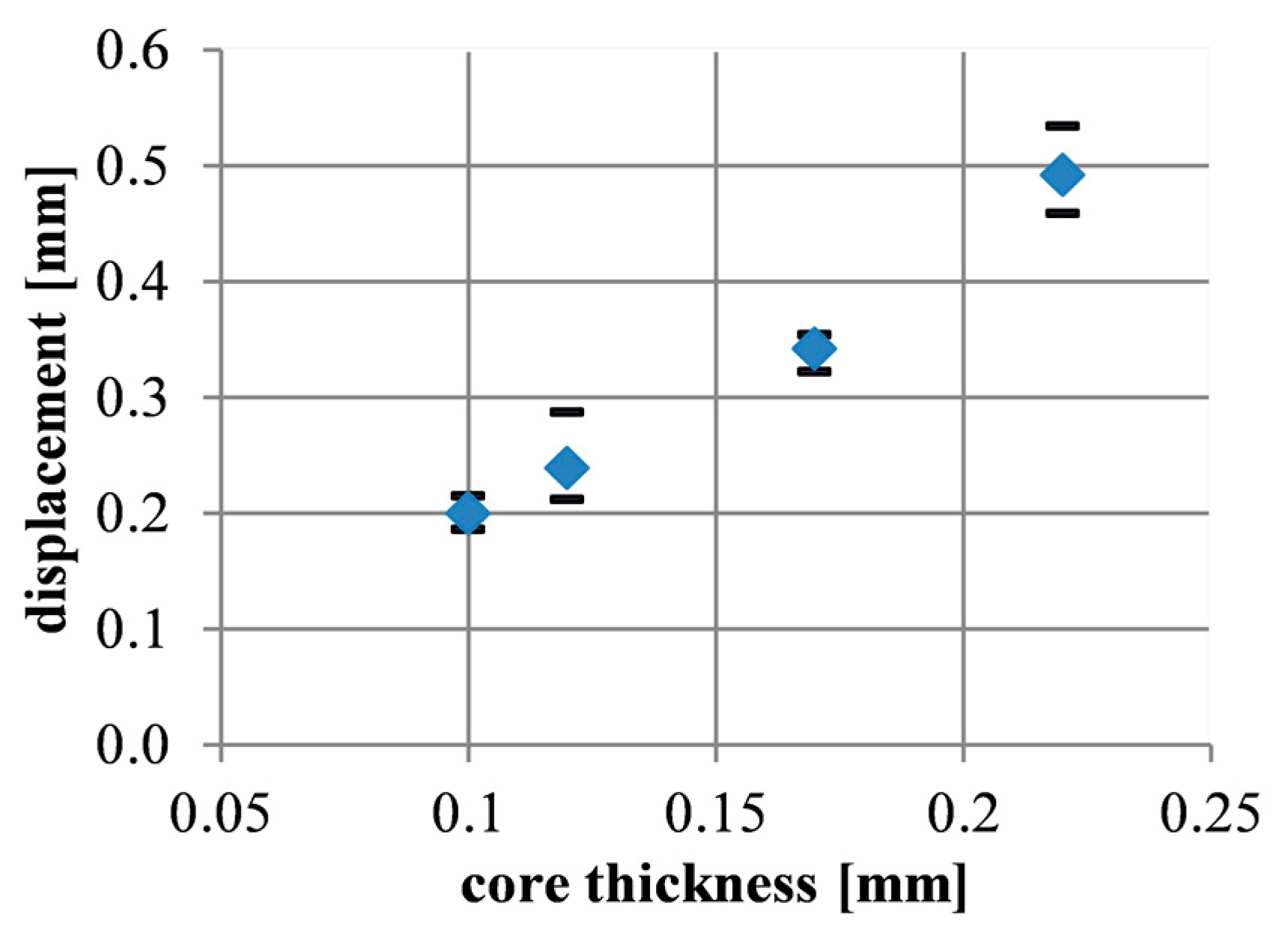
However, the displacement of the specimen leads to an increase from an average of 0.2 mm to an average of 0.5 mm in path with an increasing layer thickness (Figure 12). This is caused by the proportionality between the layer thickness and the displacement. Due to the calculation of the shear strain γ = Δl/sap the shear strain remains almost constant at γ = 2.15 by varying the layer thickness (Figure 10b).
4. Conclusions
By applying the adhesion promoter to the DSC analysis, a preliminary temperature window for processing the material could be provided. By the use of single lap shear specimens, the process parameters were qualified in a further way to setup an optimized performance regarding shear strength and shear strain.
The series of experiments determined that the shear strength and the shear strain depends on the varied parameters of temperature, pressing time, and adjusted layer thickness. In the examined process window, the highest sensitivity regarding shear strength and shear strain occurs when the temperature is varied.
At a temperature of 150 °C, which is slightly above the melting temperature of 140 °C, the failure does not occur in the metal/adhesion promoter interlayer. At higher temperatures up to 190 °C, the adhesion promoter shows an increasing performance up to a shear stress of 18.9 MPa. If the limit value is exceeded, the decomposition of the adhesion promoter begins, which can be obtained from Figure 3. The beginning of the decomposition results in a reduction in strength and shear strain [18]. At the same time, a coloration of the coated surface occurs. With the determined parameters, a maximum shear strength of τmax = 18.9 MPa and shear strain of γm = 2.24 occurs at 190 °C and 90 s holding time.
In further research, the determined parameters will be validated by cross tension tests. With the produced sandwich sheets the influence of the strain rate and testing temperature will be investigated. For the numerical investigation of the material, a FE Model will be developed afterwards.
Author Contributions
Benedikt Poggel and Bernd Engel conceived and designed the experiments; Benedikt Poggel performed the experiments; Benedikt Poggel and Bernd Engel analyzed the data; Benedikt Poggel and Bernd Engel wrote the paper.
Conflicts of Interest
The authors declare no conflict of interest.
References
- Thyssen Krupp InCar plus. Einsatzpotential von Litecor in der Karosserie. ATZ Extra 2014, 19, 108–111. [Google Scholar]
- Poggel, B.; Schwarzer, R.; Paul, C.; Vogt, O.; Wollmann, T.; Hahn, M.; Meschut, G.; Wiedemann, S.; Wessels, H.; Wetterau, H.-J.; et al. Leika - effiziente Mischbauweisen für Leichtbau-Karosserien. Abschlussbericht; Plattform FOREL: Dresden, Germany, 2017. (In German) [Google Scholar]
- Kalyanasundaram, S.; DharMalingam, S.; Venkatesan, S.; Sexton, A. Effect of process parameters during forming of self reinforced–PP based Fiber Metal Laminate. Compos. Struct. 2013, 97, 332–337. [Google Scholar] [CrossRef]
- Zal, V.; Naeini, H.M.; Bahramian, A.R.; Sinke, J. Investigation of the effect of temperature and layup on the press forming of polyvinyl chloride-based composite laminates and fiber metal laminates. Int. J. Adv. Manuf. Technol. 2017, 89, 207–217. [Google Scholar] [CrossRef]
- Buhl, J. Umformeigenschaften von Sandwichblechen; Shaker Verlag: Aachen, Germany, 2013. (In German) [Google Scholar]
- da Silva, Lucas F.M.; Rodrigues, T.N.S.S.; Figueiredo, M.A.V.; de Moura, M.F.S.F.; Chousal, J.A.G. Effect of Adhesive Type and Thickness on the Lap Shear Strength. J. Adhes. 2006, 82, 1091–1115. [Google Scholar] [CrossRef]
- Lange, G. Beitrag zum Umformverhalten von Dreischichtigen Austenitischen Sandwichverbunden mit Polymerer Kernschicht; 1. Aufl.; Piepersche Druckerei & Verlag: Clausthal-Zellerfeld, Germany, 2006; ISBN 978-3-923605-28-6. (In German) [Google Scholar]
- Kim, J.-K.; Yu, T.-X. Forming and failure behaviour of coated, laminated and sandwiched sheet metals: A review. J. Mater. Process. Technol. 1997, 63, 33–42. [Google Scholar] [CrossRef]
- Palkowski, H.; Sokolova, O.A.; Carradò, A. Sandwich Materials. In Encyclopedia of Automotive Engineering; Crolla, D., Foster, D.E., Kobayashi, T., Vaughan, N., Eds.; John Wiley & Sons, Ltd: Chichester, UK, 2014; pp. 1–17. [Google Scholar]
- Behrens, B.-A.; Rosenberger, J.; Dilger, K.; Wisner, G. Erweiterung von Prozessgrenzen der Bonded Blank Technologie durch hydromechanische Umformung. In FAT-Schriftenreihe; Verband der Automobilindustrie, Ed.: Berlin, Germany, 2011. (In German) [Google Scholar]
- Baranowski, T. Handbuch Kunststoff-Metall-Hybridtechnik. Hylight; Lehrstuhl für Kunststofftechnik, Prof. Dr.-Ing. Dietmar Drummer, Friedrich-Alexander-Universität Erlangen-Nürnberg: Erlangen-Tennenlohe, Germany, 2015; ISBN 978-3-931864-66-8. (In German) [Google Scholar]
- Pietschmann, J. Oberflächenvorbehandlung von Metallen. In Industrielle Pulverbeschichtung; Pietschmann, J., Ed.; Springer Fachmedien Wiesbaden: Wiesbaden, Germany, 2013; pp. 209–294. (In German) [Google Scholar]
- Evonik. VESTAMELT® Hylink: Crosslinkable Copolyamide Adhesion Promoter for Hybrid Components; Technical Information; Evonik Industries AG: Marl, Germany, 2014. (In German) [Google Scholar]
- Frick, A.; Stern, C. DSC-Prüfung in der Anwendung; 2., aktualisierte und erw. Aufl.; Hanser: München, Germany, 2013; ISBN 9783446436909. (In German) [Google Scholar]
- Habenicht, G. Kleben - erfolgreich und fehlerfrei. Handwerk, Praktiker, Ausbildung, Industrie; 6., überarb. und erg. Aufl.; Vieweg + Teubner: Wiesbaden, Germany, 2012; ISBN 978-3-8348-1585-9. (In German) [Google Scholar]
- Klebstoffe - Bestimmung der Zugscherfestigkeit von Überlappungsklebungen. DIN EN 1465; DIN Deutsches Institut für Normung e.V: Berlin, Germany, 2009. (In German)
- Swentek, I.; Wood, J.T. Measuring polymer composite interfacial strength. Compos. Part B Eng. 2014, 58, 235–241. [Google Scholar] [CrossRef]
- ASM International. Characterization and Failure Analysis of Plastics; ASM International: Materials Park, OH, USA, 2010. [Google Scholar]
- Zeus Industrial Products, Inc. Thermal Degradation of Plastics: Technical Whitepaper; Zeus Inc.: Letterkenny, Ireland, 2005. [Google Scholar]
- Arenas, J.M.; Narbón, J.J.; Alía, C. Optimum adhesive thickness in structural adhesives joints using statistical techniques based on Weibull distribution. Int. J. Adhes. Adhes. 2010, 30, 160–165. [Google Scholar] [CrossRef]
- Bobbert, M.; Schwarzkopf, G.; Schlimmer, M.; Meschut, G. Influences of manufacturing tolerances on the crash-behavior of adhesive bonds. In Proceedings of the 37th Annual Meeting of the Adhesion Society 2014, San Diego, CA, USA, 23–26 February 2014; Curran: Red Hook, NY, USA, 2014. [Google Scholar]
Figure 1.
Schematic layering of a sandwich composite.

Figure 2.
Schematic temperature profile for (a) burning in and (b) consolidation process.
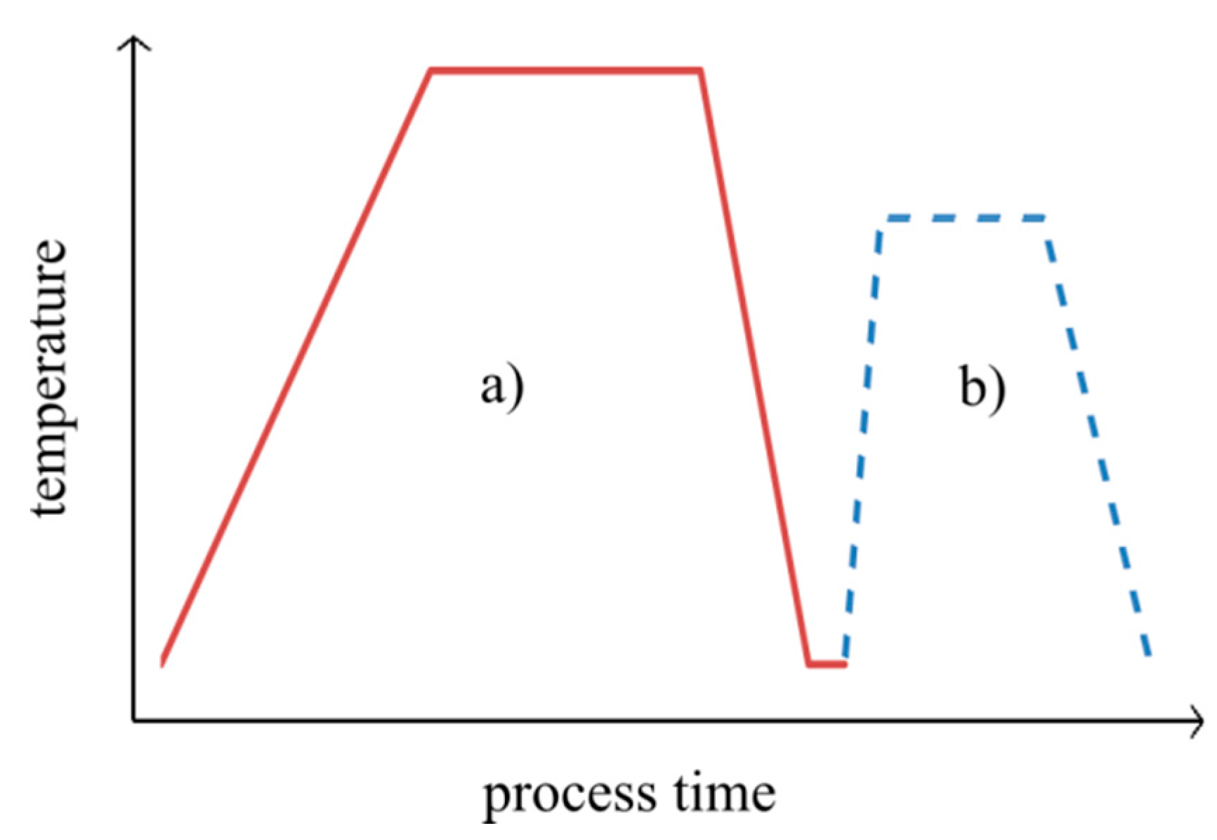
Figure 3.
DSC analysis: second heating (corresponds to consolidating).

Figure 4.
Tool setup for consolidation of specimen.

Figure 5.
Force and temperature in relation to the consolidation time measured during the consolidation process.
Figure 5.
Force and temperature in relation to the consolidation time measured during the consolidation process.
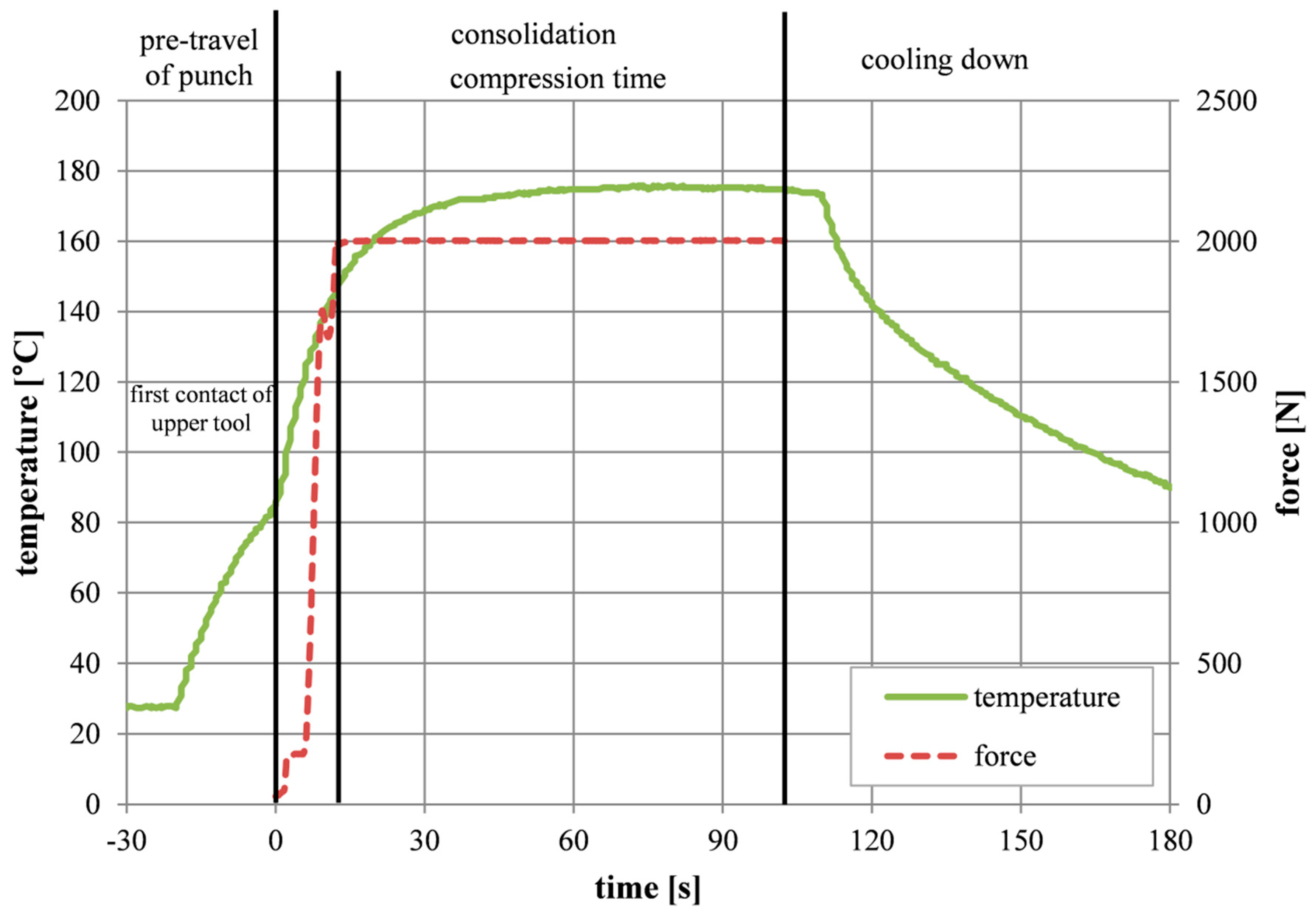
Figure 6.
(a) Shear test specimen before testing; (b) Schematic shear stress shear strain curve.
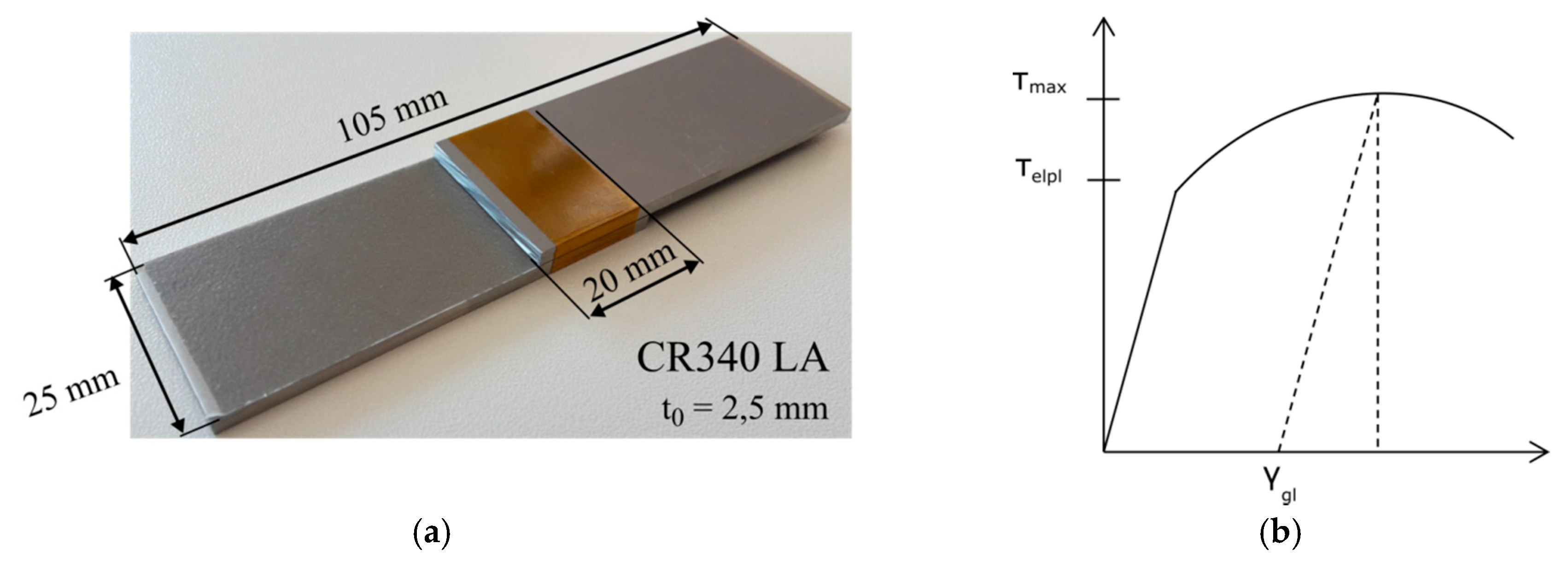
Figure 7.
(a) Shear strength as a function of temperature (shv = 0.16 mm; t = 90 s); (b) Shear strain as a function of temperature (shv = 0.16 mm; t = 90 s).
Figure 7.
(a) Shear strength as a function of temperature (shv = 0.16 mm; t = 90 s); (b) Shear strain as a function of temperature (shv = 0.16 mm; t = 90 s).

Figure 8.
(a) Fracture in the interstice insufficient; (b) Fracture on the substrate (adhesive failure).
Figure 8.
(a) Fracture in the interstice insufficient; (b) Fracture on the substrate (adhesive failure).

Figure 9.
(a) Shear stress as a function of compression time (shv = 0,16 mm; T = 190 °C); (b) Shear strain as a function of compression time (shv = 0.16 mm; T = 190 °C).
Figure 9.
(a) Shear stress as a function of compression time (shv = 0,16 mm; T = 190 °C); (b) Shear strain as a function of compression time (shv = 0.16 mm; T = 190 °C).
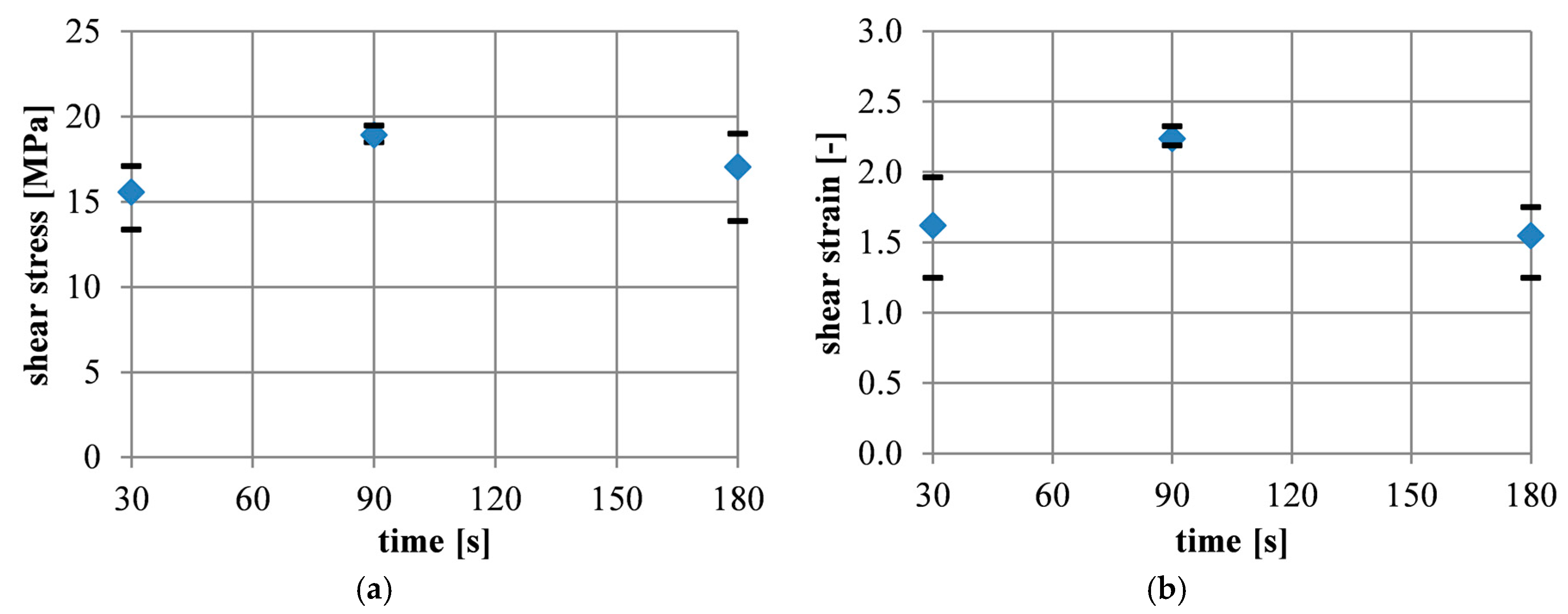
Figure 10.
(a) Shear stress as a function of adhesion promoter thickness (T = 190 °C; t = 90 s); (b) Shear strain as a function of adhesion promoter thickness (T = 190 °C; t = 90 s).
Figure 10.
(a) Shear stress as a function of adhesion promoter thickness (T = 190 °C; t = 90 s); (b) Shear strain as a function of adhesion promoter thickness (T = 190 °C; t = 90 s).

Figure 11.
Shear strength displacement diagram for shear specimen with a different core layer thickness.
Figure 11.
Shear strength displacement diagram for shear specimen with a different core layer thickness.
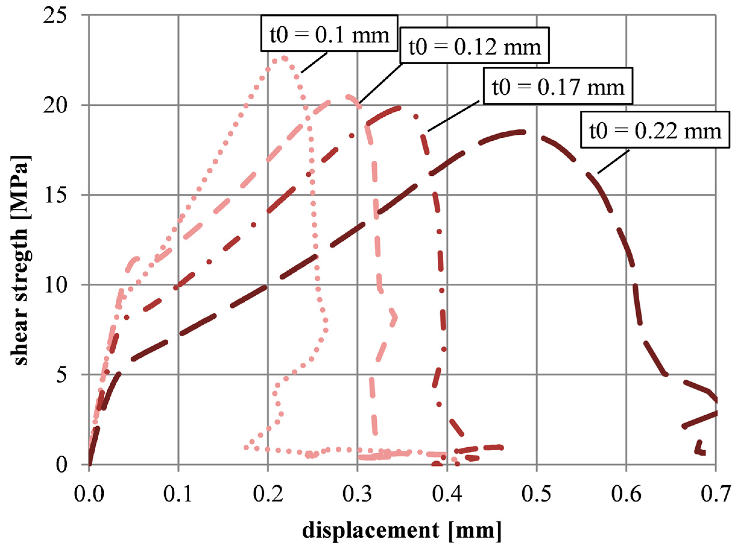
Figure 12.
Displacement as a function of adhesion promoter thickness (average values).

Table 1.
Parameter variation during the manufacturing of the test specimens.
| Serie | Temperature T (°C) | Compression Time tc (s) | Layer Thickness sap (mm) |
|---|---|---|---|
| Set 1 | 150; 170; 190; 210 | 90 | 0.16 |
| Set 2 | 190 | 30; 60; 180 | 0.16 |
| Set 3 | 190 | 90 | 0.1; 0.12; 0.16; 0.22 |
Table 2.
Average values and standard deviation of shear stress and shear strain.
| Adhesive layer thickness t0 (mm) | t0 = 0.1 mm | t0 = 0.12 mm | t0 = 0.17 mm | t0 = 0.22 mm |
|---|---|---|---|---|
| Average shear stress τmax [MPa] | 21.51 (s = 1.38) | 21.19 (s = 0.89) | 20.25 (s = 0.51) | 18.46 (s = 0.32) |
| Average shear strain γm [-] | 0.204 (s = 0.015) | 0.241 (s = 0.034) | 0.339 (s = 0.028) | 0.455 (s = 0.031) |
© 2017 by the authors. Licensee MDPI, Basel, Switzerland. This article is an open access article distributed under the terms and conditions of the Creative Commons Attribution (CC BY) license (http://creativecommons.org/licenses/by/4.0/).
Share and Cite
MDPI and ACS Style
Poggel, B.; Engel, B. Parameter Study and Method for Processing an Adhesion Promoter for Manufacturing Sandwich Sheets. J. Compos. Sci. 2017, 1, 5. https://doi.org/10.3390/jcs1010005
AMA Style
Poggel B, Engel B. Parameter Study and Method for Processing an Adhesion Promoter for Manufacturing Sandwich Sheets. Journal of Composites Science. 2017; 1(1):5. https://doi.org/10.3390/jcs1010005
Chicago/Turabian StylePoggel, Benedikt, and Bernd Engel. 2017. "Parameter Study and Method for Processing an Adhesion Promoter for Manufacturing Sandwich Sheets" Journal of Composites Science 1, no. 1: 5. https://doi.org/10.3390/jcs1010005