Fused Deposition Modelling of Natural Fibre/Polylactic Acid Composites


Department of Engineering, University of Waikato, Gate 1 Knighten Road, Private Bag 3105, Hamilton 3240, New Zealand
*
Author to whom correspondence should be addressed.
J. Compos. Sci. 2017, 1(1), 8; https://doi.org/10.3390/jcs1010008
Submission received: 16 June 2017
/
Revised: 9 August 2017
/
Accepted: 11 August 2017
/
Published: 14 August 2017
Abstract
:Fused deposition modelling is a simple additive manufacturing technology utilising fine filament extrusion of predominantly thermoplastic materials to build 3D objects layer by layer. This research explores the feasibility and the factors involved in using fused deposition modelling to produce natural fibre reinforced composite components. Uniform 3-mm filaments of both hemp and harakeke (Phormium tenax) in varying weight percentages within polylactic acid (PLA) polymer were successfully produced and used to print tensile test samples. Tensile test results supported harakeke to be a useful fibre in terms of mechanical properties achieved which surpassed the Young’s modulus and tensile strength of plain PLA samples by 42.3% and 5.4%, respectively.
1. Introduction
Hailed as the third industrial revolution and recognised as a textbook disruptive technology, additive manufacturing or 3D printing is changing the way we think about manufacturing [1]. To manufacture a component using this technology, modelling software is first used to generate a virtual component. The 3D model is then divided into incremental layers in the xy-plane. Precision machinery is then used to deposit or solidify material in these layers matching the geometric model [2]. Collectively, the layers form a solid replica of the three-dimensional model which is then ready for use. There are numerous advantages to this process as opposed to traditional manufacturing, such as up to 90% material savings, accelerated product prototyping, and practically no limit to the complexity of the product [1,2,3].
Fused deposition modelling (FDM) is an additive manufacturing technology that creates 3D parts through directionally orientated extrusion using a miniature extrusion die ~0.5–2 mm in diameter. The technical simplicity and relatively low price make FDM the most widely used form of additive manufacturing by the general public [4,5].
The materials used to produce 3D-printed objects through FDM and similar processes are mainly thermoplastic polymers, but also include ceramics, metals, and composites [6,7,8]. Composite filaments have been developed, which incorporate a range of different synthetic fibres. Zhong et al. [7] found improvement by the addition of short glass fibre in an acrylonitrile–butadiene–styrene (ABS) matrix for use in FDM. Tekinelp et al. [9] found that the addition of short carbon fibres to ABS polymer increased the tensile strength and Young’s modulus by 115% and 700%, respectively. 3D printing with continuous carbon fibre in a PLA matrix has also been conducted using a modified FDM printer, giving strengths of 185 and 57 MPa, respectively [11]. Synthetic fibre filaments are available commercially, however, they require specialized FDM systems, such as those produced by MarkForged Inc. (Cambridge, MA, USA) (glass, carbon, and Kevlar reinforced filaments are available commercially), which are currently much more expensive than standard FDM printers.
Increasing environmental awareness over recent years has prompted the development of natural fibre-reinforced polymer composites to replace synthetic petrochemical materials. Natural fibre composites not only have the potential to be biodegradable and renewable, but also possess several other advantages such as being lightweight, low-cost, and have high specific strength.
The application of natural fibre composites to 3D printing technology is a relatively new field with an absence found by the authors in the literature showing applications in standard fused deposition modelling. Over the past few years, there has been growing popularity of FDM in the consumer market [1]. When coupled with an increasing awareness of our effect on the environment, natural fibre composite filaments have a promising future. If the filament also exhibits superior properties typical to composites, this would provide a competitive advantage against other print filaments currently on offer.
This research aims to explore the potential use of natural fibres hemp and harakeke formed into individual composites using a PLA matrix. Fibre composites produced through FDM are used to interpret the advantages and disadvantages associated with the incorporation of short natural fibres.
2. Experimental
2.1. Materials
Harakeke fibre was grown in the south island of New Zealand and supplied in bundle form from the Templeton Flax mill, Riverton.
Hemp fibre, provided by the Hemp Farm NZ Ltd. (Rotorua, New Zealand), was locally grown from October 2012 and harvested in February 2013 after 120 days. Green hemp stalks were air dried for two weeks and then the bast fibre was hand separated from the stalks.
PLA3052D powder was supplied from Nature Works LLC (Minnetonka, MN, USA). This was kept in an oven at 85 °C for 48 h prior to use in composites.
2.2. Alkalifibre Reatment
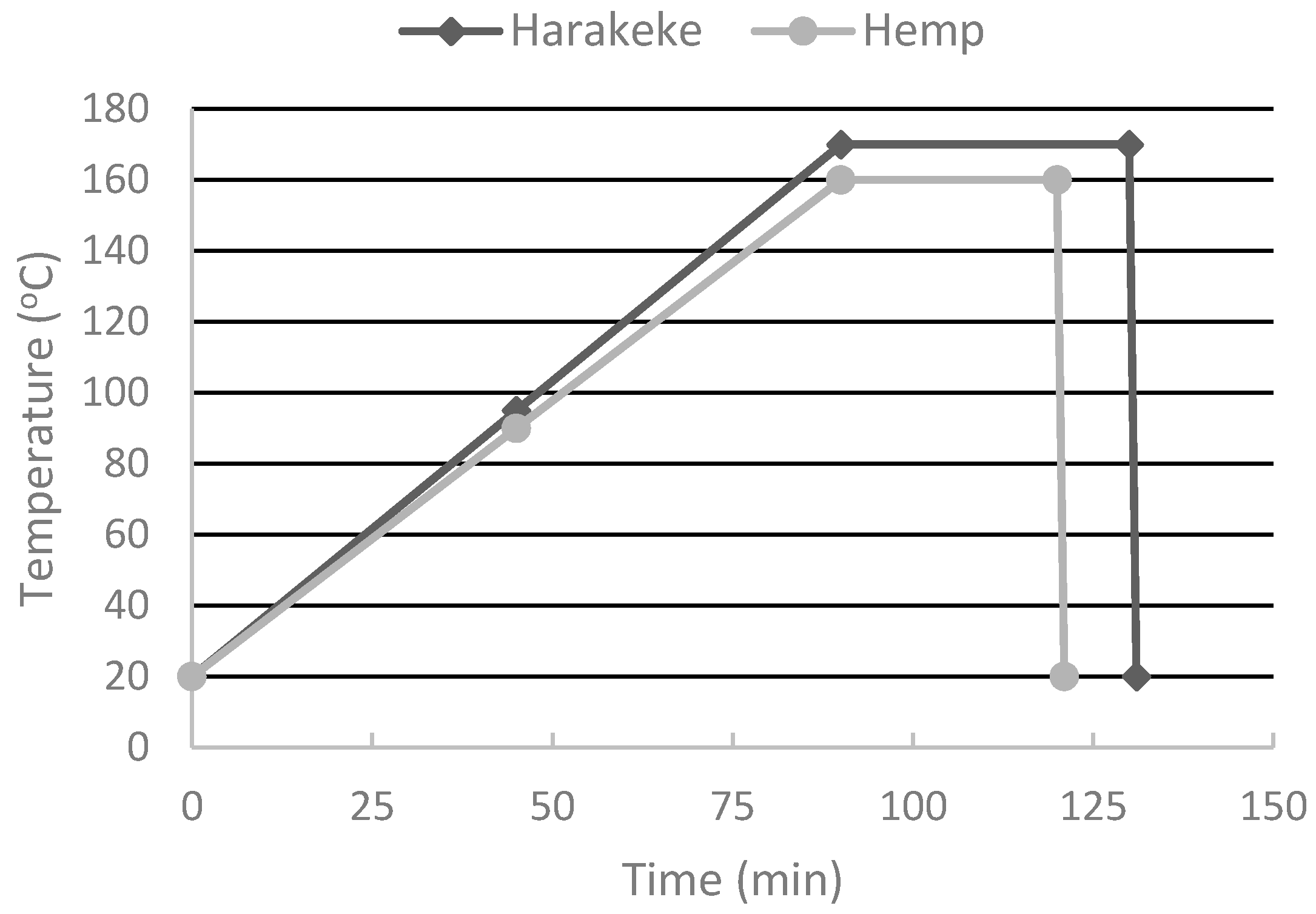
Fibres were first processed through a Castin granulator using an 8-mm sieve. These fibres were then placed in stainless steel canisters and combined with alkali solution at a fibre to solution ratio of 1:8. Treatments for hemp and harkake were slightly different based on optimal treatments obtained in previous work [8]. The treatment solution used consisted of 5% NaOH for hemp and 5% NaOH with 2% sodium sulphite for harakeke [11]. The steel canister was then placed in a laboratory scale digester (typically used for paper making) and set to run according to the scheme in Figure 1. The maximum treatment temperature was 160 °C for hemp and 170 °C for harakeke, which was held for 30 min for hemp and 40 min for harakeke, respectively.
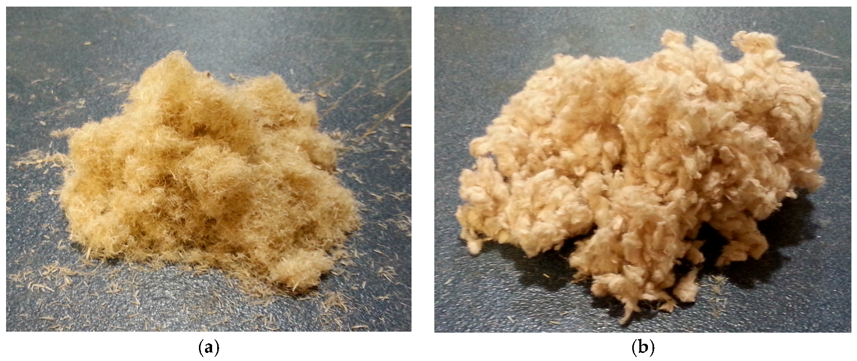
After digestion, the fibres were removed from the canisters, then washed thoroughly with cool tap water before being dried in an oven for 48 h at 103 °C (Figure 2a,b). Diameters of fibres were measured before and after digestion at five different points long their length by means of an Olympus BX60F5 (Olympus Corporation, Tokyo, Japan) optical microscope. An average was taken from 30 different fibres. It was found that fibre diameters were reduced from 13.0 to 12.3 (±1.7) μm for harakeke and from 34.9 to 28.3 (±8.3) μm for hemp during treatment [11].
2.3. Filament Formation
Initial mixing was carried out using an intensive mixer consisting of a heated chamber and two specially shaped rotating shafts. Composites with fibre contents of 10, 20, and 30 wt % were mixed in small batches at 185 °C at an average of 16 rpm. The composites were allowed to solidify at room temperature before granulation through an 8-mm sieve. These granules were then extruded using a ThermoPrism TSE-16-TC twin screw extruder with a 3-mm diameter die. The five barrel temperatures of the extruder were maintained from outlet to inlet at 183, 180, 174, 152, and 159 °C.
To achieve a consistent filament cross-section, an electric spooling machine was developed (see Figure 3). By controlling the extrusion and filament spooling machine rotational speeds, the filament would coil itself around the cylinder, solidifying in transit. Controlling the distance (x in Figure 3) between the extruded filament and the bench would allow the cross-section to be within ±0.5 mm.
2.4. Sample Printing
All extruded filament was kept in sealed bags at room temperature prior to sample printing. A 2014 Diamond age 3D printer was used to print five dog bone samples of each material type, with software settings adjusted for each composite composition to produce consistent rectangular samples measuring 10 mm × 15 mm × 3 mm. In-fill geometry was based on the use of concentric shapes starting with the outline of the sample, as shown in Figure 4, and working inwards. Printing was carried out in a standard laboratory without temperature or humidity control. A 1-mm nozzle was used, giving a layer thickness of approximately 1 mm. The heating bed was set at a temperature at 110 °C.
2.5. Mechanical Testing
Tensile tests were performed using an Instron 33R4204 (Instron, Norwood, MA, USA) universal testing machine equipped with a 5 kN load cell at a test speed of 1 mm/min. All tensile test samples were printed on the same day and stored in sealed bags for 48 h prior to testing.
2.6. Scanning Electron Microscope (SEM)
SEM micrographs of hemp and harakeke composite filament extrusion fracture surfaces were taken using a Hitachi S-4100 (Hitachi, Tokyo, Japan) field emission scanning electron microscope (SEM). Samples were mounted on aluminium stubs using carbon tape observing the longitudinal and transverse sample sections. The composites were then coated with plasma sputtering to avoid the sample becoming charged under the electron beam.
3. Results and Discussion
3.1. Surface Finish
Samples appeared less glossy and became coarser with increasing fibre content, as seen elsewhere [12,13]. Printing the composites through a 1-mm die showed that at fibre contents of 20 wt % and above, there were sporadic semi-blockages of the die leading to slip-stick extrusion; the exit velocity would momentarily increase, bringing about a reduction in dimensional control. This caused poor layer adhesion and an uneven surface effect on each layer, as shown in Figure 4.
This effect was rare for the 20 wt % fibre samples, but occurred in all of the 30 wt % samples for both hemp and harakeke. Increasing the diameter of the extrusion die to 2 mm eliminated this effect but decreased the definition of the finished samples. Figure 5 and Figure 6 show micrographs taken of either side of a 30 wt % harakeke tensile-tested sample. The pores indicated in the figures would expected to act as considerable stress concentration points and contribute to the sample failing at this point.
FDM relies on the fusion of each cylindrical extrusion to form the solid shape and minimise localised stress concentration points. These pores are likely due to insufficient fusion of the layers in the printing process. As fusion is largely reliant on the viscosity [14], reducing the viscosity would be a logical next step. Recent studies have shown that introducing citrate plasticizers have successfully reduced the viscosity, melting, and glass transition temperatures of PLA with little effect on the mechanical properties [15,16]. In addition to a less viscous composite exiting the nozzle, the lower melting temperature may help with fusing the already solidified layers to the hot layers by melting them together more effectively. Controlling the melt rheology has also been shown to be the most practical way to reduce fibre breakage and achieve better fibre distribution [17,18].
3.2. SEM Analysis
Pores were observed in the extruded filament, as shown in Figure 7, which appeared to retain their size when printed through a 1-mm die (see Figure 8), which was of concern due to the potential adverse effects on the mechanical properties of the printed samples. Fibre pull-out was also observed, suggesting poor adhesion between fibre and matrix that is typically more common in natural fibre composites [19,20,21], leading to poor mechanical properties.
3.3. Mechanical Properties
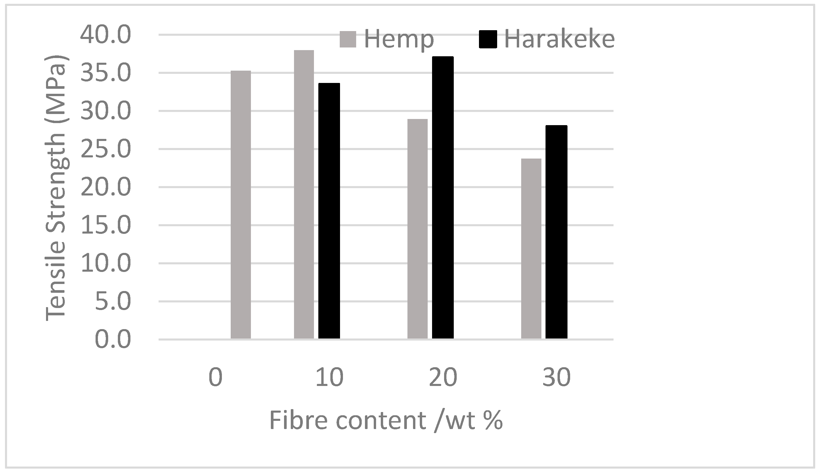
Figure 9 shows the effect of increasing fibre content on tensile strength in comparison with plain PLA for printed samples. The general trend shows a decrease in tensile strength with increasing fibre content. The exception to this was for 20 wt % harakeke, which showed an average increase of 5.4% compared to PLA although the average value fell within variation for PLA. Low strengths are likely to be due to void content within the filament and between strands in samples as well as poor interfacial bonding.
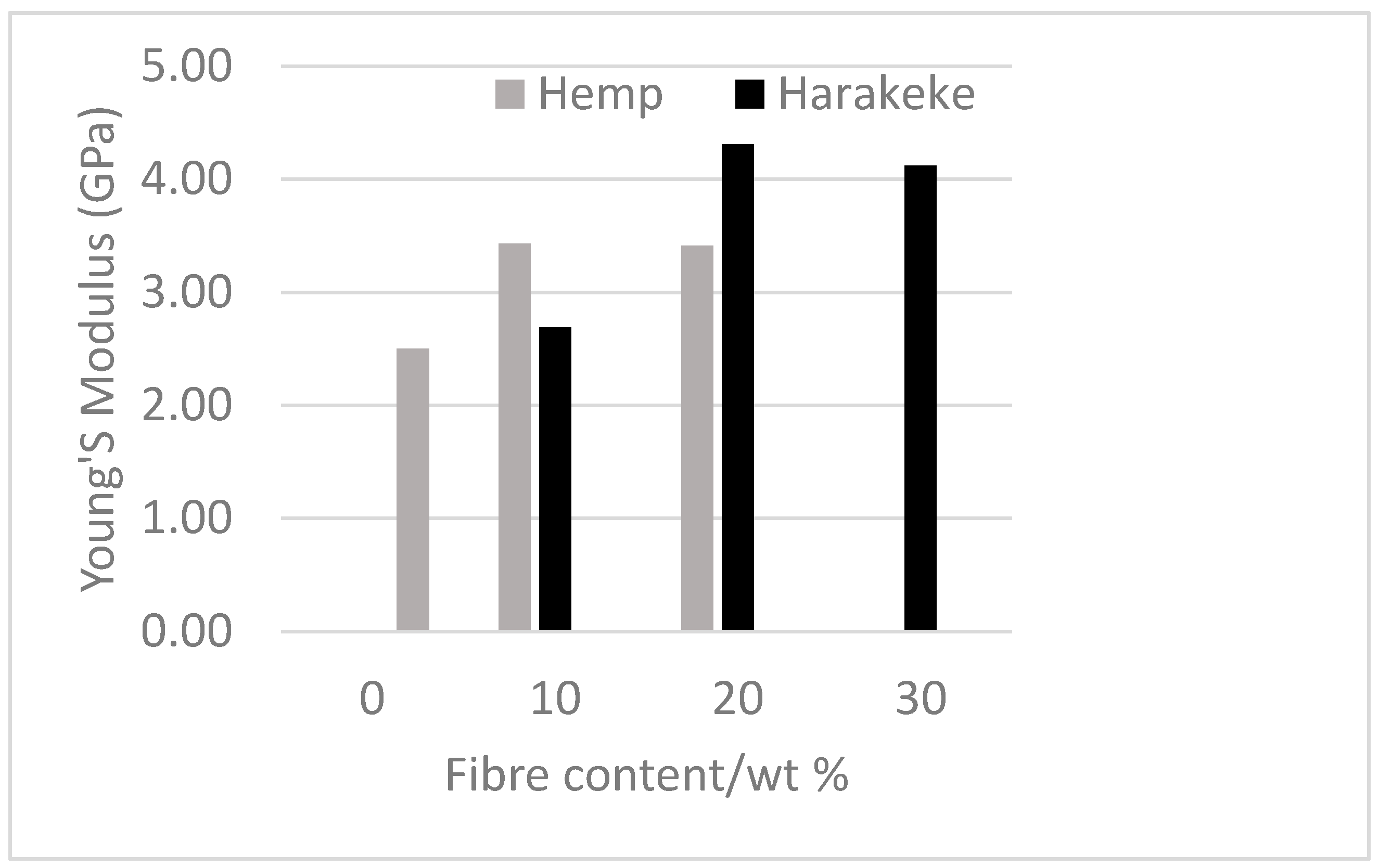
In contrast to the trend for tensile strength, the Young’s modulus (Figure 10) tended to increase with increasing fibre content. Once again the best results were observed to be for 20 wt % harakeke, which was 42.5% higher than that of PLA. The Young’s moduli and tensile strengths of 20 wt % harakeke are also greater than those for hemp composites of the same fibre content. This could be due to harakeke fibre being finer and typically having a better aspect ratio than hemp [22].
4. Conclusions
This study was carried out as an initial step towards the use of natural fibre composites in the developing world of additive manufacturing. Evaluation of mechanical properties showed that improvement in the tensile strength of PLA is possible with the addition of natural fibre. The addition of plasticizer is suggested for the improvement of surface finish, layer adhesion, decreased pore size, and ultimately the performance of the composite. The further development of this technology could lead to filling a gap in the growing market as an environmentally friendly alternative with useful mechanical properties.
Acknowledgments
This work was supported by the Hamilton City and Waikato District Councils.
Author Contributions
Kim Pickering and David Stoof conceived and designed the experiments; David Stoof performed the experiments; Kim Pickering and David Stoof analyzed the data; Yuanji Zhang provided technical support and advice for machine configuration and materials testing; David Stoof and Kim Pickering wrote the paper.
Conflicts of Interest
The authors declare no conflict of interest.
References
- Zhai, Y.W.; Lados, D.A.; LaGoy, J.A. Additive manufacturing: Making imagination the major limitation. JOM 2014, 66, 808–816. [Google Scholar] [CrossRef]
- Huang, S.H.; Liu, P.; Mokasdar, A.; Hou, L. Additive manufacturing and its societal impact: A literature review. Int. J. Adv. Manuf. Technol. 2013, 67, 1191–1203. [Google Scholar] [CrossRef]
- Urbonaite, G.; Kibirkštis, E.; Miliūnas, V. 3D print technologies analysis. In Mechanika 2013: Proceedings of the 18th International Conference; Technologija: Kaunas, Lithuania, 2013; pp. 244–247. [Google Scholar]
- Magalhes, L.C.; Volpato, N.; Luersen, M.A. Evaluation of stiffness and strength in fused deposition sandwich specimens. J. Braz. Soc. Mech. Sci. Eng. 2014, 36, 449–459. [Google Scholar] [CrossRef]
- Tong, S. MakiBox. 2014. Available online: http://www.makibox.com/ (accessed on 26 October 2014).
- Haq, R.H.A.; Wahab, M.S.B.; Jaimi, N.I. Fabrication process of polymer nano-composite filament for fused deposition modeling. Appl. Mech. Mater. 2014, 465, 8–12. [Google Scholar] [CrossRef]
- Zhong, W.H.; Li, F.; Zhang, Z.; Song, L.; Li, Z. Short fiber reinforced composites for fused deposition modeling. Mater. Sci. Eng. A 2001, 301, 125–130. [Google Scholar] [CrossRef]
- Mireles, J.; Kim, H.C.; Lee, I.H.; Espalin, D.; Medina, F.; MacDonald, E.; Wicker, R. Development of a fused deposition modeling system for low melting temperature metal alloys. J. Electron. Packag. 2013, 135, 011008. [Google Scholar] [CrossRef]
- Tekinalp, H.L.; Kunc, V.; Velez-Garcia, G.M.; Duty, C.E.; Love, L.J.; Naskar, A.K.; Blue, C.A.; Ozcan, S. Highly oriented carbon fiber-polymer composites via additive manufacturing. Compos. Sci. Technol. 2014, 105, 144–150. [Google Scholar] [CrossRef]
- Matsuzaki, R.; Ueda, M.; Namiki, M.; Jeong, T.K.; Asahara, H.; Horiguchi, K.; Nakamura, T.; Todoroki, A.; Hirano, Y. Three-dimensional printing of continuous-fiber composites by in-nozzle impregnation. Sci. Rep. 2016, 6, 23058. [Google Scholar] [CrossRef] [PubMed]
- Efendy, M.G.A.; Pickering, K.L. Comparison of harakeke with hemp fibre as a potential reinforcement in composites. Composites Part A 2014, 67, 259–267. [Google Scholar] [CrossRef] [Green Version]
- Oksman, K.; Skrifvars, M.; Selin, J.F. Natural fibres as reinforcement in polylactic acid (PLA) composites. Compos. Sci. Technol. 2003, 63, 1317–1324. [Google Scholar] [CrossRef]
- Shah, D.U. Developing plant fibre composites for structural applications by optimising composite parameters: A critical review. J. Mater. Sci. 2013, 48, 6083–6107. [Google Scholar] [CrossRef]
- Novakova-Marcincinova, L.; Novak-Marcincin, J. Testing of the ABS materials for application in fused deposition modeling technology. Appl. Mech. Mater. 2013, 309, 133–140. [Google Scholar] [CrossRef]
- Arrieta, M.P.; Samper, M.D.; López, J.; Jiménez, A. Combined effect of poly(hydroxybutyrate) and plasticizers on polylactic acid properties for film intended for food packaging. J. Polym. Environ. 2014, 22, 460–470. [Google Scholar] [CrossRef]
- Wan, T.; Yang, G.; Du, T.; Zhang, J. Tri-(butanediol-monobutyrate) citrate plasticizing poly(lactic acid): Synthesis, crystallization, thermal, and mechanical properties. Polym. Eng. Sci. 2015, 55, 205–213. [Google Scholar] [CrossRef]
- Fisa, B. Mechanical degradation of glass-fibers during compounding with polypropylene. Polym. Compos. 1985, 6, 232–241. [Google Scholar] [CrossRef]
- Yan, Z.L.; Zhang, J.C.; Lin, G.; Zhang, H.; Ding, Y.; Wang, H. Fabrication process optimization of hemp fibre-reinforced polypropylene composites. J. Reinf. Plast. Compos. 2013, 32, 1504–1512. [Google Scholar] [CrossRef] [Green Version]
- Huber, T.; Biedermann, U.; Mussig, J. Enhancing the fibre matrix adhesion of natural fibre reinforced polypropylene by electron radiation analyzed with the single fibre fragmentation test. Compos. Interfaces 2010, 17, 371–381. [Google Scholar] [CrossRef]
- Huber, T.; Mussig, J. Fibre matrix adhesion of natural fibres cotton, flax and hemp in polymeric matrices analyzed with the single fibre fragmentation test. Compos. Interfaces 2008, 15, 335–349. [Google Scholar] [CrossRef]
- Zhang, Q.; Shi, L.; Nie, J.; Wang, H.; Yang, D. Study on poly(lactic acid)/natural fibers composites. J. Appl. Polym. Sci. 2012, 125, E526–E533. [Google Scholar] [CrossRef]
- De Rosa, I.M.; Iannoni, A.; Kenny, J.M.; Puglia, D.; Santulli, C.; Sarasini, F.; Terenzi, A. Poly(lactic acid)/phormium tenax composites: Morphology and thermo-mechanical behavior. Polym. Compos. 2011, 32, 1362–1368. [Google Scholar] [CrossRef]
Figure 1.
Digestion cycle for hemp and harakeke.

Figure 2.
Digested hemp fibre (a) and digested harakeke fibre (b).

Figure 3.
Filament spooling machine.
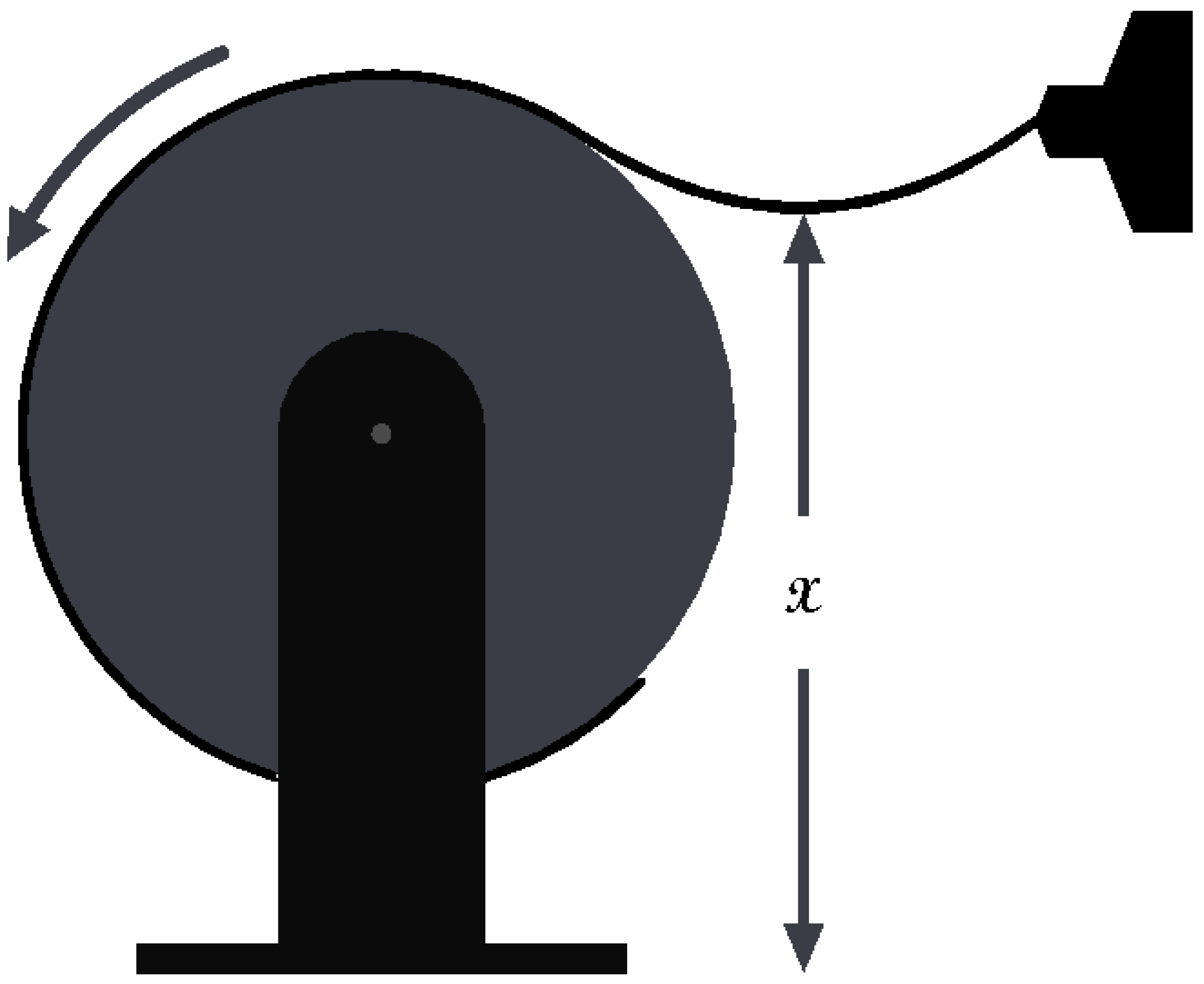
Figure 4.
Uneven surface finish of 30 wt % hemp.
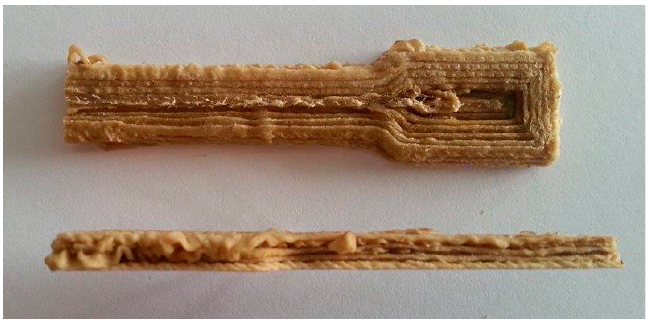
Figure 5.
30 wt % harakeke fracture surface with arrows depicting voids.
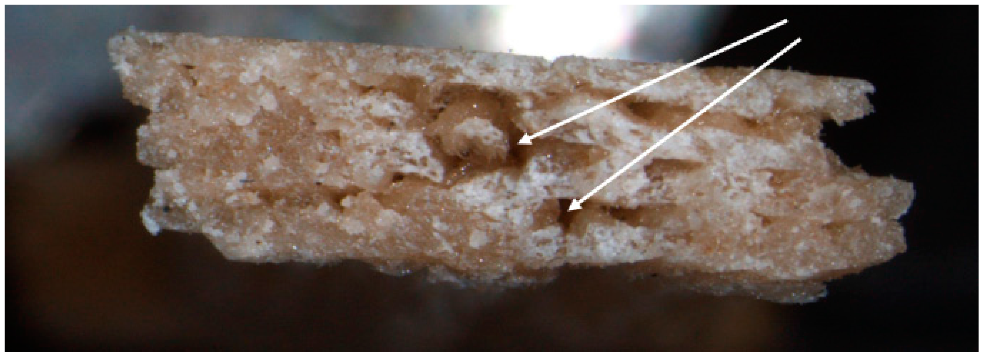
Figure 6.
30 wt % harakeke corresponding fracture surface with arrows depicting voids.
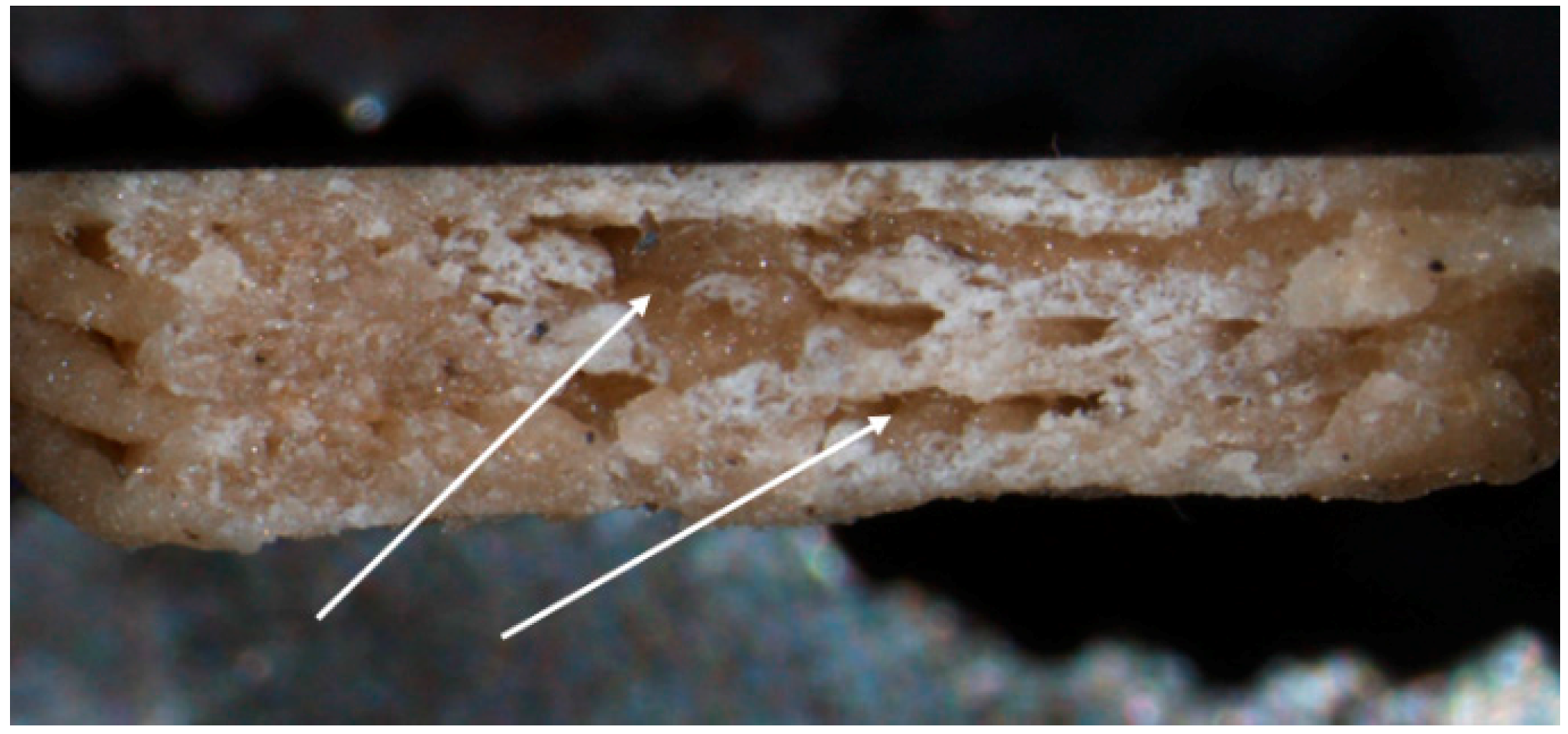
Figure 7.
20 wt % harakeke 3-mm filament cross-section.
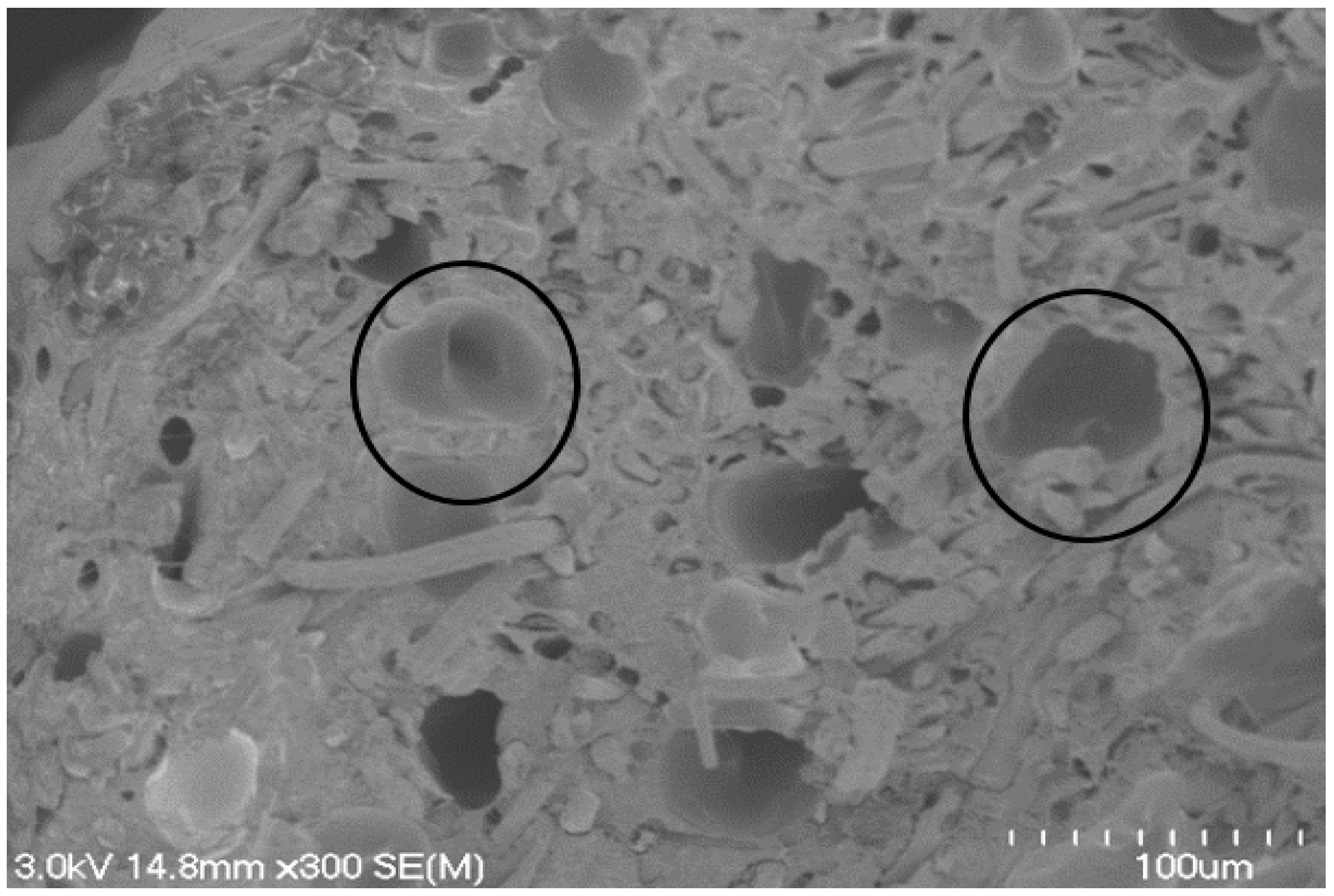
Figure 8.
20 wt % harakeke 1-mm strand cross-section.
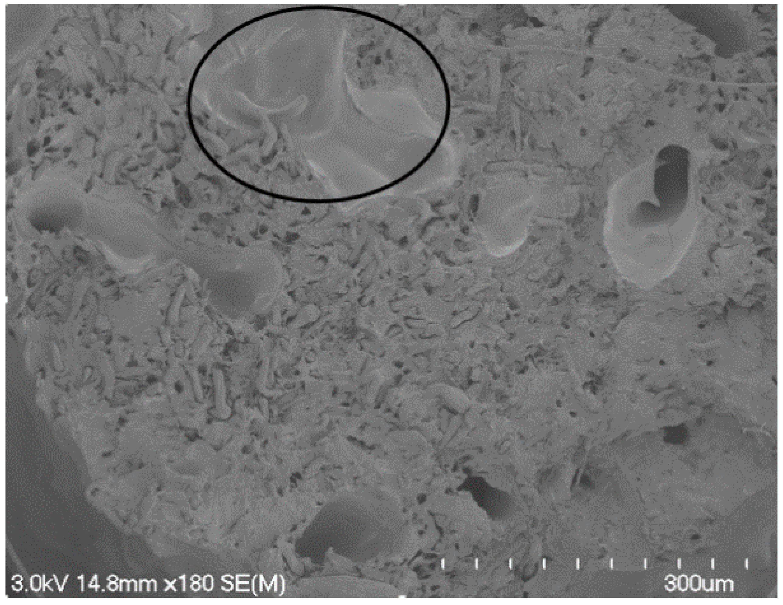
Figure 9.
Tensile strength results of PLA, 10, 20, and 30 wt % hemp and harakeke printed samples.

Figure 10.
Young’s modulus results of PLA for 10, 20, and 30 wt % hemp and harakeke.
© 2017 by the authors. Licensee MDPI, Basel, Switzerland. This article is an open access article distributed under the terms and conditions of the Creative Commons Attribution (CC BY) license (http://creativecommons.org/licenses/by/4.0/).
Share and Cite
MDPI and ACS Style
Stoof, D.; Pickering, K.; Zhang, Y. Fused Deposition Modelling of Natural Fibre/Polylactic Acid Composites. J. Compos. Sci. 2017, 1, 8. https://doi.org/10.3390/jcs1010008
AMA Style
Stoof D, Pickering K, Zhang Y. Fused Deposition Modelling of Natural Fibre/Polylactic Acid Composites. Journal of Composites Science. 2017; 1(1):8. https://doi.org/10.3390/jcs1010008
Chicago/Turabian StyleStoof, David, Kim Pickering, and Yuanji Zhang. 2017. "Fused Deposition Modelling of Natural Fibre/Polylactic Acid Composites" Journal of Composites Science 1, no. 1: 8. https://doi.org/10.3390/jcs1010008