Design and Testing of a 2D Optical Fiber Sensor for Building Tilt Monitoring Based on Fiber Bragg Gratings


1
Graduate Institute of Electrical Engineering, National Kaohsiung First University of Science and Technology, Kaohsiung 811, Taiwan
2
Graduate Institute of Photonics and Optoelectronics, National Taiwan University, Taipei 106, Taiwan
*
Author to whom correspondence should be addressed.
Appl. Syst. Innov. 2018, 1(1), 2; https://doi.org/10.3390/asi1010002
Submission received: 27 October 2017
/
Revised: 25 November 2017
/
Accepted: 27 November 2017
/
Published: 1 December 2017
Abstract
:In this paper, a new type of optical fiber tilt sensor based on fiber Bragg grating (FBG) is presented for 2D dual-axis tilt angle sensing. The tilt sensor is composed of two cylindrical floats suspended in water, connected with FBG. When the external environment causes the tilting of the sensor, the surface of the liquid within the container will form a new balanced liquid surface plane due to the gravity and change the height of the liquid at different locations in the container. So the buoyancy force of the cylindrical floats of the sensor will vary with the depth of liquid, thus the changed FBG strain will cause the FBG reflection central wavelength shift. According to the measured central wavelength shift by the optical spectral analyzer (OSA), we can obtain the two-axis tilt angle of the sensor. The proposed sensor can detect a tilt angle range of −5 degrees to +5 degrees and achieve a sensitivity of 0.1° with optical spectrum analyzer resolution of 0.01 nm. Due to its good sensing linearity, the proposed sensor can be applied in building tilt measurement.
1. Introduction
In recent years, optical fiber sensors made of silicon-based optical fibers or polymer optical fibers have been commonly utilized for numerous types of physical detection [1,2,3,4,5,6,7,8,9,10,11,12] because a fiber sensor has many features that are better than conventional electronic sensors. Fiber optic sensors can be used for large-scale distributed monitoring, and also have anti-electromagnetic interference, high sensitivity, light weight, good adaptability in shape, and electrical isolation. Fiber-optic sensors can increase or decrease the number of sensors according to system requirements. They are easy to install and can be static or dynamic.
With the development of fiber Bragg grating (FBG), the applications of fiber grating sensors have gradually increased. Not only silica optical fiber sensors but also polymer optical fibers (POF) sensors are widely used in different sensing applications. Several fiber sensor designs based on FBG have been reported for various applications, such as liquid level monitoring [13], transverse force sensing [14], concentration measurement [15], biomedical measurement [16,17], pressure [18,19,20], displacement [21,22], temperature [23,24], and ground vibration [25]. An FBG is a type of distributed Bragg reflector constructed in a short segment of optical fiber that reflects particular wavelengths of light and transmits all others. The center wavelength λB of the reflected spectral band is defined by the Bragg condition [26]:
where is the Bragg wavelength of FBG, neff is the effective refraction index of the fiber core, and Λ is the period of the index modulation. Both neff and Λ depend on temperature and strain, and consequently the Bragg wavelength is sensitive to both strain and temperature. By measuring the wavelength change accurately, the physical properties can be measured. The shift of a Bragg wavelength due to the change in temperature () and the change in applied strain () can be expressed as [27]:
where is the thermal expansion coefficient, is the thermo-optic coefficient, and is the strain-optic coefficient of the optical fiber. In general, when the temperature of FBG is increased or decreased by 1 °C, it will cause the FBG reflection central wavelength to shift about by 0.0115–0.012 nm. In this study, the effect of stress on the wavelength shift of FBG is much greater than that of temperature, so the effect of temperature is neglected.
Recently, several FBG-based tilt sensors with different configurations for one- or two-dimensional (1D or 2D) measurements have been reported [28,29,30,31]. Tilt angle measurement is very important for many applications, such as the fields of aviation and civil engineering. In this paper, we develop a novel fiber tilt sensor for public construction monitoring. It has the advantages of simple structure and low cost. Furthermore, the FBG tilt sensor can embed a fiber optic communication module to achieve real-time sensing and monitoring.
2. The Configuration of the Proposed Tilt Sensor
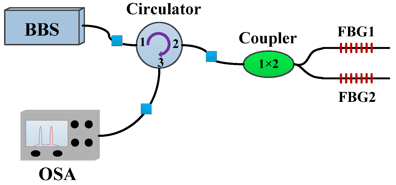
Figure 1 shows the simple architecture of the optical path of the design of the sensing system, in which the proposed fiber tilt sensor observes the two FBGs reflecting the center wavelength shift amount to determine the tilt of the azimuth and angle. We use the C + L band broadband light source (BBS) and a three-port optical circulator as the input, sense, and output ports. The first port of the circulator was connected to the broadband source; the second port was connected to the coupler and FBGs. When the sensing signals are reflected by the FBGs into the third port of the optical circulator, they will be displayed on the optical spectrum analyzer (OSA).
The proposed tilt sensor is composed of two cylindrical floats suspended in water, connected with FBG fiber gratings. Because the cylindrical float is attracted by gravity, it is always facing the center of the earth. When the sensor is tilted, it will drive the cylindrical float to move, causing the buoyancy force to change. That will cause the FBG to be stretched or contracted to change the center wavelength of the reflection light. Figure 2 shows the configuration of the proposed FBG tilt sensor. In this configuration, the size of the container and cylindrical float will affect the sensitivity. As the container and cylindrical float become larger, the sensitivity of the sensing will also rise. In this study, we used a rectangular container that has a length and width of 34 cm, a height of 14 cm, and two cylindrical floats with a radius of 4.3 cm and a height of 6 cm. In order to sink the cylindrical float to the liquid level 3.5 cm, we put some sand in the cylindrical float to increase the weight. Then, two aluminum bars were fixed and orthogonal above the container containing the liquid, and the FBG and the cylindrical float were connected to the north and west positions of the container, respectively (see Figure 2). The FBGs are made of photosensitive boron and germanium co-doped optical fiber (Fibercore PS1250/1500), with numerical aperture of 0.14 and cut-off at 1159 nm. At room temperature without external force, the reflection center wavelengths of FBG1 and FBG2 are 1548.877 nm and 1551.84 nm, respectively.
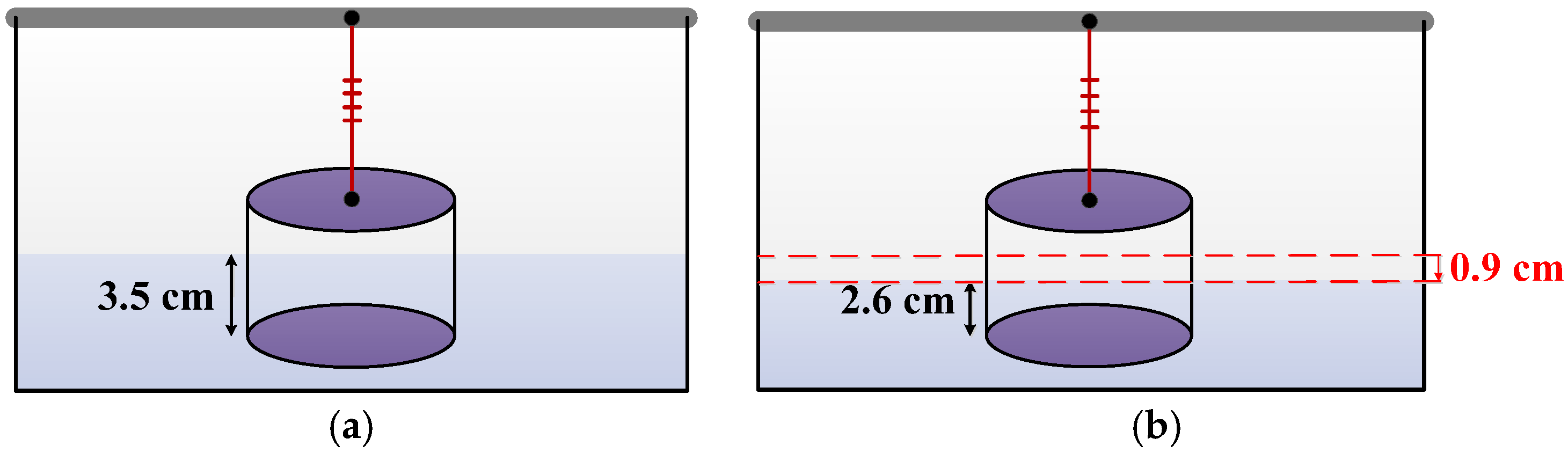
When the fiber grating is connected with the cylindrical float, the sustained weight is 0 g of FBG, as shown in Figure 3a. In order to produce a pre-stretched effect of the fiber grating, we reduced the height of the liquid in the container by 0.9 cm, to reduce the buoyancy of the liquid on cylindrical float 52 grams, in order to increase the tension on the FBG fiber grating, as shown in Figure 3b. The advantage of this pre-stretched operation is that only one fiber grating can be used to do one-dimensional tilt sensing. Therefore, the cost can be reduced, and the production is simple. Compared with the tilt detectors described in the literature previously, we only need two fiber gratings to do 2D tilt sensing, not four. The proposed tilt sensor can also maintain better sensitivity.
3. Experimental Results and Discussion
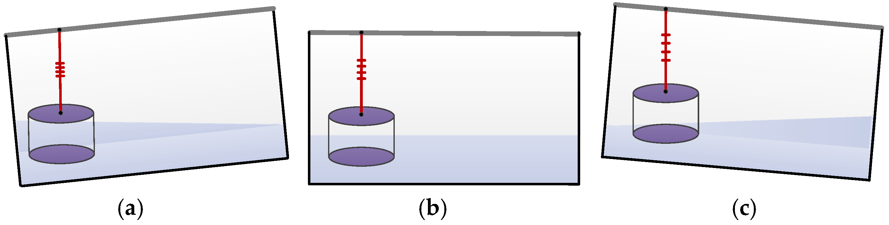
Because the tilt sensor is composed of two suspended cylindrical floats, each connected with FBG, we can do two-dimensional tilt sensing (see Figure 2). We have verified this proposed sensor’s performance in four tilt directions: east–west, south–north, northeast–southwest, and northwest–southeast. In the sensing process, when the FBG is stretched or contracted, the reflection center wavelength of the FBG will change. In this research, we assume that the FBG’s tension becomes larger and the tilt angle is positive. On the other hand, the tension of FBG becomes smaller and the tilt angle is negative. Figure 4 shows that the cylindrical float is immersed in a different height of liquid, and the buoyancy of the cylindrical float is also different, causing the pitch of the fiber grating to change. From the reflection center wavelength shift, we can calculate the inclination of the azimuth and the inclination angle of the test object.
Figure 5 shows the measurement of the wavelength shift of the FBGs when the sensor was tilted in the east–west direction. The angle of inclination of the sensor to the east is positive, and the angle to the west is set to be negative. As the buoyancy of the cylindrical float changes to make the FBG bear the weight change, the FBG located in the west can cause expansion or contraction. When the sensor is tilted to the east, the buoyancy of the cylindrical float decreases as the water level decreases. Therefore, FBG1 is stretched and the center wavelength of FBG1 is shifted to the long wavelength band. At the same time, the center wavelength of FBG2 does not change because it is not subject to the impact of the tensile. When the sensor is tilted towards a negative angle (west), FBG1 gradually shrinks as the angle increases, and the center wavelength of FBG1 begins to move toward the short wavelength band. The center wavelength of FBG2 does not change because it is nt subject to the impact of the tensile. From the experimental results, the sensitivity of FBG1 is 0.132 nm/°. In Figure 5, the coefficient of determination of FBG1, R2, is 0.998.
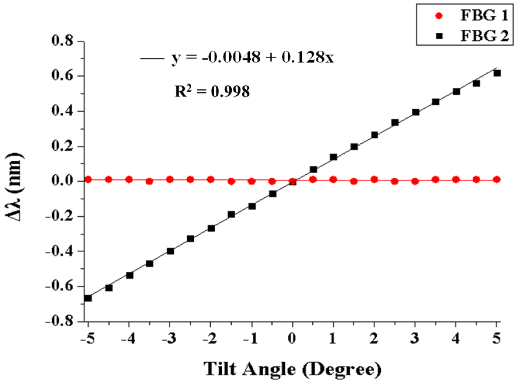
When the sensor was tilted in the south–north direction, the principle was the same as for east–west. While the tilt angle was gradually tilted from 0 degree to a positive angle (south), the FBG2 was gradually stretched as the tilt angle increased, and the reflection center wavelength of the FBG2 began to shift to a long wavelength band. The measurement results are shown in Figure 6. Since the FBG1 is located in the center of the south–north direction, the center wavelength did not change because it was not affected by stretching. Similarly, if the sensor was gradually tilted from 0 degrees to a negative angle (north), FBG2 gradually shrank as the tilt angle increased, and the reflection center wavelength of FBG2 began to shift to a short wavelength band. The center wavelength of FBG1 also did not change because it was not subject to the impact of the tensile. From the experimental results, the sensitivity of FBG2 is 0.128 nm/° and the coefficient of determination of FBG2, R2, is also 0.998.
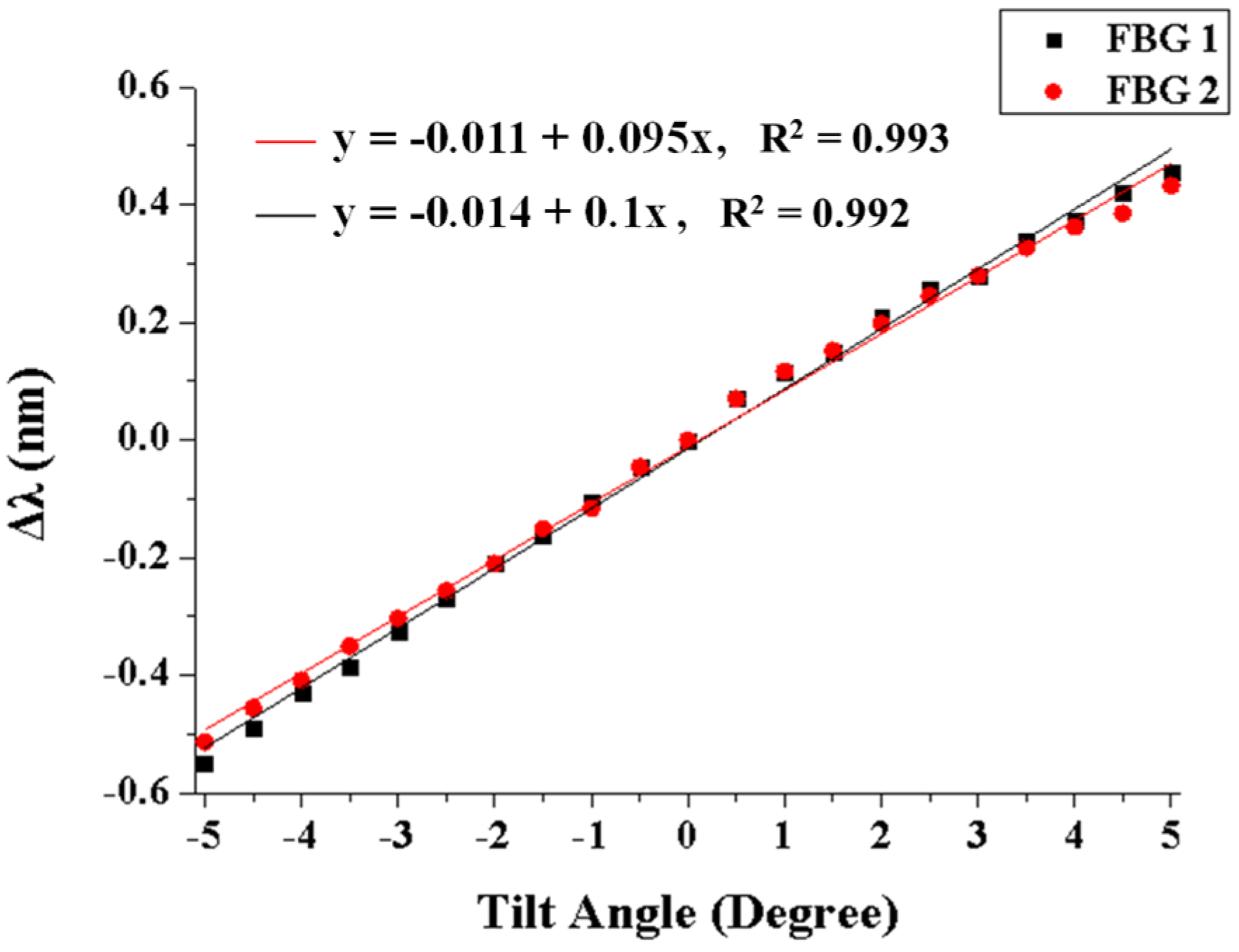
Figure 7 shows the tilt measurement results of the center wavelength shift of FBG1 and FBG2 in the southeast–northwest direction when the tilt angle was increased from −5° to 5°. The angle of inclination to the southeast is set to positive, and it will reduce the buoyancy of the cylindrical float on the two FBGs, so the FBG’s reflection center wavelength drifts to the long wavelength. The tilt angle to the northwest is set to negative; because the water level increases, it will make the buoyancy of the cylindrical float on the two FBGs increase so the FBG reflection center wavelength will shift to a short wavelength band. That is, the sensor was tilted to the southeast or northwest direction; the buoyancy changes are the same for the two cylindrical floats. As a result, the fiber grating is simultaneously stretched or contracted. From the experimental results, in this azimuth angle, the sensitivities of FBG1 and FBG2 are 0.1 nm/°and 0.095 nm/°, respectively.
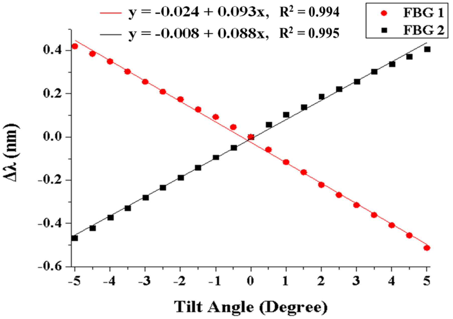
When the sensor is tilted toward the northeast or southwest, the measurement results of the center wavelength shift of two FBGs are shown in Figure 8. The tilt angle of the sensor towards the northeast is negative and the tilt angle towards the southwest is positive. Because the sensor is tilted toward the northeast or southwest, the water level of one of the floats will increase and the water level of the other float will drop. That is, the two fiber gratings in the container will change. One is stretched and the other shrinks. As a result, the reflected center wavelength of the contracted FBG will be shifted to shorter wavelength, whereas the reflected center wavelength of the stretched FBG will be shifted to longer wavelength. In this azimuth, the sensitivities of FBG1 and FBG2 are 0.093 nm/° and 0.088 nm/°, respectively.
4. Conclusions
In this paper, we have experimentally investigated a 2D tilt sensor based on two FBGs with orthogonal setup onto cylindrical floats for 2D tilt measurement. When the sensor is tilted, the buoyancy acting on the cylindrical floats will change due to the flow of the liquid. The greater the buoyancy of the float, the smaller the pulling force acting on the FBG. Accordingly, the center wavelength of the reflection will shift to a short wavelength. On the contrary, the smaller the buoyancy, the more FBG is stretched, causing the center wavelength of the reflection to shift to a long wavelength. From the change of reflection center wavelength of FBG, we can find the tilt angle and tilt direction. In building regulations, the definition of building tilt ratio is the ratio of building offset and height. For example, the building is 100 m high, and when the building is tilted 1 m, the building tilt ratio is 1%. If the inclination of the building exceeds 1/40, that is, the inclination reaches 1.43 degrees, the reconstruction standard will be reached. The experimental results show that the design of the sensor was feasible for a tilt angle range of −5° to +5°. Therefore, the tilt sensor of this study is sufficient for tilt detection application in buildings. The sensitivity of FBG1 and FBG2 are 0.132 nm/° and 0.128 nm/°, respectively. The proposed tilt sensor structure is simple in addition to the advantages of low cost and high sensing stability. It can be used to monitor the tilt angle of buildings to protect human life and property.
Author Contributions
Chung-Ru Chao and Wei-Lun Liang co-designed the research. Chung-Ru Chao performed the experiments. Wei-Lun Liang provided statistical analysis of the experimental data and measurement recommendations. Tsair-Chun Liang evaluated the results and wrote the manuscript.
Conflicts of Interest
The authors declare no conflict of interest.
References
- Tosi, D.; Saccomandi, P.; Schena, E.; Duraibabu, D.B.; Poeggel, S.; Leen, G.; Lewis, E. Intra-tissue pressure measurement in ex vivo liver undergoing laser ablation with fiber-optic Fabry-Perot probe. Sensors 2016, 16, 544. [Google Scholar] [CrossRef] [PubMed]
- Saccomandi, P.; Oddo, C.M.; Zollo, L.; Formica, D.; Romeo, R.A.; Massaroni, C.; Caponero, M.A.; Vitiello, N.; Guglielmelli, E.; Silvestri, S.; et al. Feedforward neural network for force coding of an MPI-compatible tactile sensor array based on fiber Bragg grating. J. Sens. 2015, 2015, 367194. [Google Scholar] [CrossRef]
- Liang, T.C.; Lin, Y.L. A fiber-optic sensor for the ground vibration detection. Opt. Commun. 2013, 306, 190–197. [Google Scholar] [CrossRef]
- Feng, M.Q.; Kim, D.H. Novel fiber optic accelerometer system using geometric moire fringe. Sens. Actuators A 2006, 128, 37–42. [Google Scholar] [CrossRef]
- Huang, H.S.; Liang, T.C. The fabrication and analysis of lateral pressure fiber sensor based on fiber Bragg grating. Microw. Opt. Techn. Lett. 2008, 50, 2535–2537. [Google Scholar] [CrossRef]
- Liang, T.C.; Huang, H.S.; Chuang, M.H. Study on fiber grating sensors for concentration measurement of cottonseed oil adulteration in pure olive oil. Microelectron. Eng. 2015, 148, 21–24. [Google Scholar] [CrossRef]
- Acheroy, S.; Merken, P.; Ottevaere, H.; Geernaert, T.; Thienpont, H.; Marques, C.A.F.; Webb, D.J.; Peng, G.D.; Mergo, P.; Berghmans, F. Thermal effects on the photoelastic coefficient of polymer optical fibers. Opt. Lett. 2016, 41, 2517–2520. [Google Scholar]
- Alberto, N.; Tavares, C.; Domingues, M.F.; Correia, S.F.H.; Marques, C.; Antunes, P.; Pinto, J.L.; Ferreira, R.A.S.; André, P.S. Relative humidity sensing using micro-cavities produced by the catastrophic fuse effect. Opt. Quantum Electron. 2016, 48, 1–8. [Google Scholar] [CrossRef]
- Marques, C.A.F.; Bilro, L.; Kahn, L.; Oliveira, R.A.; Webb, D.J.; Nogueira, R.N. Acousto-optic effect in microstructured polymer fiber Bragg gratings: Simulation and experimental overview. J. Lightwave Technol. 2013, 31, 1551–1558. [Google Scholar] [CrossRef]
- Pospori, A.; Marques, C.A.F.; Sáez-Rodríguez, D.; Nielsen, K.; Bang, O.; Webb, D.J. Thermal and chemical treatment of polymer optical fiber Bragg grating sensors for enhanced mechanical sensitivity. Opt. Fiber Technol. 2017, 36, 68–74. [Google Scholar] [CrossRef]
- Marques, C.A.F.; Webb, D.J.; Andre, P. Polymer optical fiber sensors in human life safety. Opt. Fiber Technol. 2017, 36, 144–154. [Google Scholar] [CrossRef]
- Alberto, N.J.; Marques, C.A.; Pinto, J.L.; Nogueira, R.N. Three-parameter optical fiber sensor based on a tilted fiber Bragg grating. Appl. Opt. 2010, 49, 6085–6091. [Google Scholar] [CrossRef]
- Marques, C.A.F.; Peng, G.D.; Webb, D.J. Highly sensitive liquid level monitoring system utilizing polymer fiber Bragg gratings. Opt. Express 2015, 23, 6058–6072. [Google Scholar] [CrossRef] [PubMed]
- Hu, X.; Saez-Rodriguez, D.; Marques, C.; Bang, O.; Webb, D.J.; Mégret, P.; Caucheteur, C. Polarization effects in polymer FBGs: Study and use for transverse force sensing. Opt. Express 2015, 23, 4581–4590. [Google Scholar] [CrossRef] [PubMed]
- Melo, L.B.; Rodrigues, J.M.M.; Farinha, A.S.F.; Marques, C.A.; Bilro, L.; Alberto, N.; Tomé, J.P.C.; Nogueira, R.N. Concentration sensor based on a tilted fiber Bragg grating for anions monitoring. Opt. Fiber Technol. 2014, 20, 422–427. [Google Scholar] [CrossRef]
- Prasad, A.S.G.; Omkar, S.N.; Vikranth, H.N.; Anil, V.; Chethana, K.; Asokan, S. Design and development of Fiber Bragg Grating sensing plate for plantar strain measurement and postural stability analysis. Measurement 2014, 47, 789–793. [Google Scholar] [CrossRef]
- Dziuda, L.; Skibniewski, F.W.; Krej, M.; Lewandowski, J. Monitoring respiration and cardiac activity using fiber Bragg grating-based sensor. IEEE Trans. Biomed. Eng. 2012, 59, 1934–1942. [Google Scholar] [CrossRef] [PubMed]
- Al-Fakih, E.A.; Osman, N.A.A.; Adikan, F.R.M.; Eshraghi, A.; Jahanshahi, P. Development and validation of fiber Bragg grating sensing pad for interface pressure measurements within prosthetic sockets. IEEE Sens. J. 2016, 16, 965–974. [Google Scholar] [CrossRef]
- Chang, Y.T.; Yen, C.T.; Wu, Y.S.; Cheng, H.C. Using a fiber loop and fiber Bragg grating as a fiber optic sensor to simultaneously measure temperature and displacement. Sensors 2013, 13, 6542–6551. [Google Scholar] [CrossRef] [PubMed]
- Liang, T.C.; Lin, J.J.; Guo, L.Y. Plantar pressure detection with fiber Bragg gratings sensing system. Sensors 2016, 16, 1766. [Google Scholar] [CrossRef] [PubMed]
- Li, J.; Neumann, H.; Ramalingam, R. Design, fabrication, and testing of fiber Bragg grating sensors for cryogenic long-range displacement measurement. Cryogenics 2015, 68, 36–43. [Google Scholar] [CrossRef]
- Jiang, Q.; Hu, D. Microdisplacement sensor based on tilted fiber bragg grating transversal load effect. IEEE Sens. J. 2011, 11, 1776–1779. [Google Scholar] [CrossRef]
- Cavaiola, C.; Saccomandi, P.; Massaroni, C.; Tosi, D.; Giurazza, F.; Frauenfelder, G.; Zobel, B.B.; Matteo, F.M.D.; Caponero, M.A.; Polimadei, A.; et al. Error of a temperature probe for cancer ablation monitoring caused by respiratory movements: Ex vivo and in vivo analysis. IEEE Sens. J. 2016, 16, 5934–5941. [Google Scholar] [CrossRef]
- Marques, R.D.S.; Prado, A.R.; Antunes, P.F.D.C.; André, P.S.D.B.; Ribeiro, M.R.N.; Frizera-Neto, A.; Pontes, M.J. Corrosion Resistant FBG-Based Quasi-Distributed Sensor for Crude Oil Tank Dynamic Temperature Profile Monitoring. Sensors 2015, 15, 30693–30703. [Google Scholar] [CrossRef] [PubMed]
- Liang, T.C.; Lin, Y.L. Ground vibrations detection with fiber optic sensor. Opt. Commun. 2012, 285, 2363–2367. [Google Scholar] [CrossRef]
- Melle, S.M.; Liu, K.; Measures, R.M. Practical fiber-optic Bragg grating strain gauge system. Appl. Opt. 1993, 32, 3601–3609. [Google Scholar] [CrossRef] [PubMed]
- Ma, G.M.; Li, C.R.; Quan, J.T.; Jiang, J.; Cheng, Y.C. A fiber Bragg grating tension and tilt sensor applied to icing monitoring on overhead transmission lines. IEEE Trans. Power Del. 2011, 26, 2163–2170. [Google Scholar] [CrossRef]
- Dong, X.; Zhan, C.; Hu, K.; Shum, P.; Chan, C.C. Temperature-insensitive tilt sensor with strain-chirped fiber bragg gratings. IEEE Photon. Technol. Lett. 2005, 17, 2394–2396. [Google Scholar] [CrossRef]
- Bao, H.; Dong, X.; Zhang, S.; Zhao, C.; Chan, C.C.; Shum, P. Temperature-insensitive 2-D pendulum clinometer using two fiber bragg gratings. IEEE Photon. Technol. Lett. 2010, 22, 863–865. [Google Scholar] [CrossRef]
- Ni, K.; Dong, X.; Jin, Y.; Xu, H. Temperature-independent fiber bragg grating tilt sensor. Microw. Opt. Technol. Lett. 2010, 52, 2250–2252. [Google Scholar] [CrossRef]
- Peng, B.J.; Zhao, Y.; Yang, J.; Zhao, Y. Tilt sensor with FBG technology and matched FBG demodulating method. IEEE Sens. J. 2006, 6, 63–66. [Google Scholar] [CrossRef]
Figure 1.
The optical path diagram of the proposed tilt sensor.

Figure 2.
Schematic diagram of the proposed FBG tilt sensor.
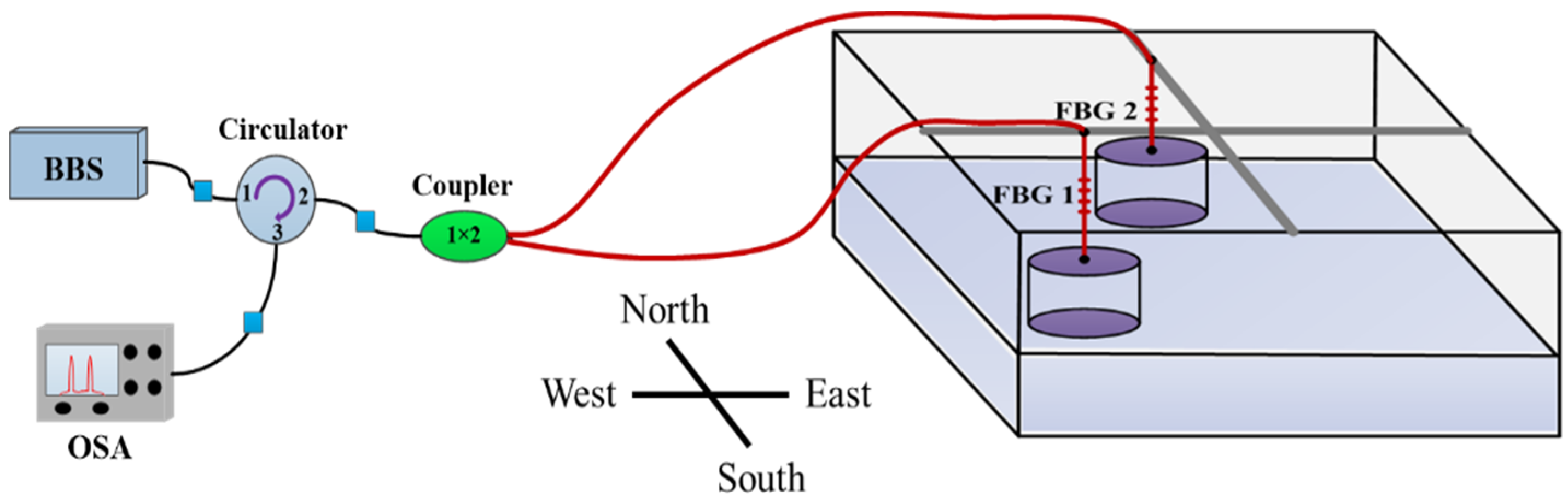
Figure 3.
The pre-tension schematic of FBG: (a) the sustained weight was 0 g; (b) the sustained weight was 52 g.
Figure 3.
The pre-tension schematic of FBG: (a) the sustained weight was 0 g; (b) the sustained weight was 52 g.

Figure 4.
The schematic of the tilt sensor: (a) was tilted toward a negative angle, (b) not tilted; and (c) tilted toward a positive angle.
Figure 4.
The schematic of the tilt sensor: (a) was tilted toward a negative angle, (b) not tilted; and (c) tilted toward a positive angle.

Figure 5.
Measured wavelength shift of FBG1 and FBG2 in the east–west direction when the tilt angle is increased from −5° to 5°.
Figure 5.
Measured wavelength shift of FBG1 and FBG2 in the east–west direction when the tilt angle is increased from −5° to 5°.
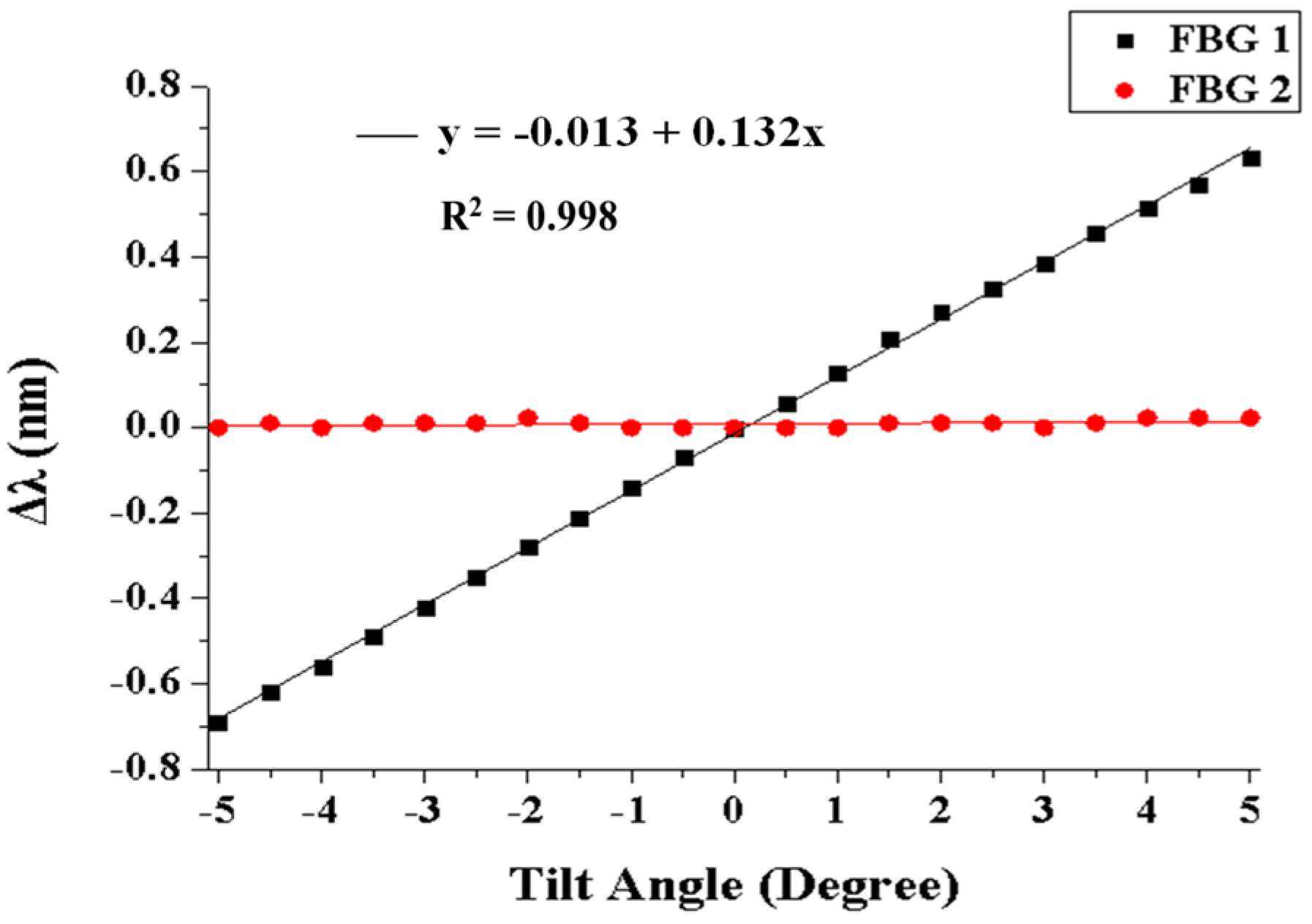
Figure 6.
Measured wavelength shift of FBG1 and FBG2 in the south–north direction when the tilt angle is increased from −5° to 5°.
Figure 6.
Measured wavelength shift of FBG1 and FBG2 in the south–north direction when the tilt angle is increased from −5° to 5°.

Figure 7.
Measured wavelength shift of FBG1 and FBG2 in the southeast–northwest direction when the tilt angle is increased from −5° to 5°.
Figure 7.
Measured wavelength shift of FBG1 and FBG2 in the southeast–northwest direction when the tilt angle is increased from −5° to 5°.

Figure 8.
Measured wavelength shift of FBG1 and FBG2 in the northeast–southwest direction when the tilt angle is increased from −5° to 5°.
Figure 8.
Measured wavelength shift of FBG1 and FBG2 in the northeast–southwest direction when the tilt angle is increased from −5° to 5°.

© 2017 by the authors. Licensee MDPI, Basel, Switzerland. This article is an open access article distributed under the terms and conditions of the Creative Commons Attribution (CC BY) license (http://creativecommons.org/licenses/by/4.0/).
Share and Cite
MDPI and ACS Style
Chao, C.-R.; Liang, W.-L.; Liang, T.-C. Design and Testing of a 2D Optical Fiber Sensor for Building Tilt Monitoring Based on Fiber Bragg Gratings. Appl. Syst. Innov. 2018, 1, 2. https://doi.org/10.3390/asi1010002
AMA Style
Chao C-R, Liang W-L, Liang T-C. Design and Testing of a 2D Optical Fiber Sensor for Building Tilt Monitoring Based on Fiber Bragg Gratings. Applied System Innovation. 2018; 1(1):2. https://doi.org/10.3390/asi1010002
Chicago/Turabian StyleChao, Chung-Ru, Wei-Lun Liang, and Tsair-Chun Liang. 2018. "Design and Testing of a 2D Optical Fiber Sensor for Building Tilt Monitoring Based on Fiber Bragg Gratings" Applied System Innovation 1, no. 1: 2. https://doi.org/10.3390/asi1010002