A Realistic Approach of the Maximum Work Extraction from Solar Thermal Collectors


Thermal Department, School of Mechanical Engineering, National Technical University of Athens, Heroon Polytehniou 9, Zografou, 15773 Athens, Greece
*
Author to whom correspondence should be addressed.
Appl. Syst. Innov. 2018, 1(1), 6; https://doi.org/10.3390/asi1010006
Submission received: 2 December 2017
/
Revised: 24 January 2018
/
Accepted: 25 January 2018
/
Published: 30 January 2018
(This article belongs to the Special Issue Solar Thermal Systems)
Abstract
:In this study, the maximum work extraction from the incident solar energy on solar thermal collectors is investigated by coupling solar collectors with a Carnot machine. A simplified thermal model for the solar collector performance is developed in which the radiation losses play a significant role. In every examined case, the optimum operating temperature that leads to maximum work extraction is calculated. The final results are presented parametrically, covering a great variety of real solar collectors. Moreover, the validation procedure of the developed model proves high accuracy. The results show that non-concentrating collectors should operate up to 400 K while concentrating collectors in higher temperature levels. More specifically, a parabolic trough collector can operate efficiently in temperature levels up to 850 K, while solar dish collectors can operate efficiently in temperature levels up to 1100 K. The results of this study can be exploited for the preliminary design and optimization of solar thermal systems. Moreover, a clear and realistic upper limit concerning the exergy production of solar irradiation with solar thermal collectors is given.
1. Introduction
Solar energy is a promising renewable energy source that is able to substitute the use of fossil fuel to a large degree [1,2]. Recently, more and more studies have been carried out in order to optimize the operation of solar thermal systems, and especially the concentrating solar power plants [3,4,5]. The most important parameter in the solar Plants is the operating temperature, because this parameter influences the collector efficiency and the thermodynamic cycle efficiency. Higher temperature levels make the solar collector have greater thermal losses, but the efficiency of the coupled thermodynamic cycle is greater. Moreover, the selection of the solar collector kind is dependent on the operating temperature levels. Flat plate collectors are used in low-temperature applications (up to 90 °C) for domestic hot water production, space heating, etc. [6]. Evacuated tube collectors are usually selected for applications as solar coolers, with industrial heat in the low-medium temperature range up to 150 °C [7]. At higher temperature levels, concentrating collectors are the only possible choice. The parabolic trough collector is the most mature technology for the temperature range from 200 °C to 400 °C [8,9,10], while for higher temperature levels concentrating collectors with dishes are preferred [11]. Fresnel collectors [12] and solar towers are also promising concentrating technologies for medium (up to 400 °C) and high temperatures (up to 600–700 °C), respectively.
The objective of this study is to present a model for the prediction of the maximum work production from a solar thermal collector by taking into account the main thermal and optical losses that cannot be neglected in real systems. In every case, the optimum operating temperature of the collector is determined, and then the thermal efficiency of the collector is calculated. This temperature level is the one that maximizes the work production of the coupled Carnot engine. In the literature, this quantity is generally expressed by using the exergy parameter, but this parameter does not take into account the thermal and optical losses of the solar collector. The present model takes into consideration parameters such as the collector optical efficiency and the receiver emittance in a way that corresponds to the real systems. The results of this work can be used for the accurate design of the solar thermal systems and for the determination of the realistic optimum operating temperature levels for every kind of solar collector using its basic design parameters.
2. Review up Today
2.1. Maximum Work Extraction from Solar Energy
The first way to express the maximum possible work extraction from solar irradiation uses the exergy analysis. Many researchers have investigated the exergy efficiency of the solar irradiation, and various literature equations about solar exergy have been suggested. Below, a brief literature review about the exergy flow of the solar irradiation (ηex) is given. The ambient (reference) temperature (Tamb) can be taken at 298 K (for instance) and the sun temperature (Tsun) at 5770 K.
The simplest formula is the Jeter assumption, which practically assumes the Sun to be a heat reservoir. In this case, the maximum possible extracted work is calculated according to Equation (1), which is similar to the Carnot efficiency [13]:
The next model was suggested by Spanner. This model assumes the Sun as a radiation reservoir, but it does not take into consideration the impact of the ambient in the final work production, and thus there is the term of “4/3” in this equation. Equation (2) gives the exergy efficiency of the solar irradiation, according to Spanner [13]:
Petela [13] developed a model that assumes the Sun as a radiation reservoir, and, simultaneously, it takes into consideration the environmental situation.
Parrot [14] suggested that the exergy of the solar irradiation has to include the half angle of the cone of the irradiation (δ):
Badescu [15] suggested a model for the exergy of the solar irradiation by taking into account the sun-shape, using a geometric factor (f):
2.2. Maximum Work Extraction Using Solar Collectors
The next part of the literature studies takes into account the characteristics of the solar collectors, which are closer to the real determination of the work extraction. The work extraction is dependent on the operating temperature of the system, which can be calculated with different models as they presented below.
The optimum operating temperature (Tr) of the solar collector has been suggested to be calculated by solving the Equation (6) [13,16].
Torres-Reyes et al. [17] proposed an approach closer to real solar collectors by taking into consideration the heat losses by using a constant thermal loss coefficient (UL). The optimum temperature, in this case, was calculated according to Equation (7):
This equation is a good approximation for flat plate collectors, in which the heat loss coefficient is approximately constant in low-temperature levels, but for greater temperature levels this assumption is not adequate.
3. Suggested Model
3.1. General Description
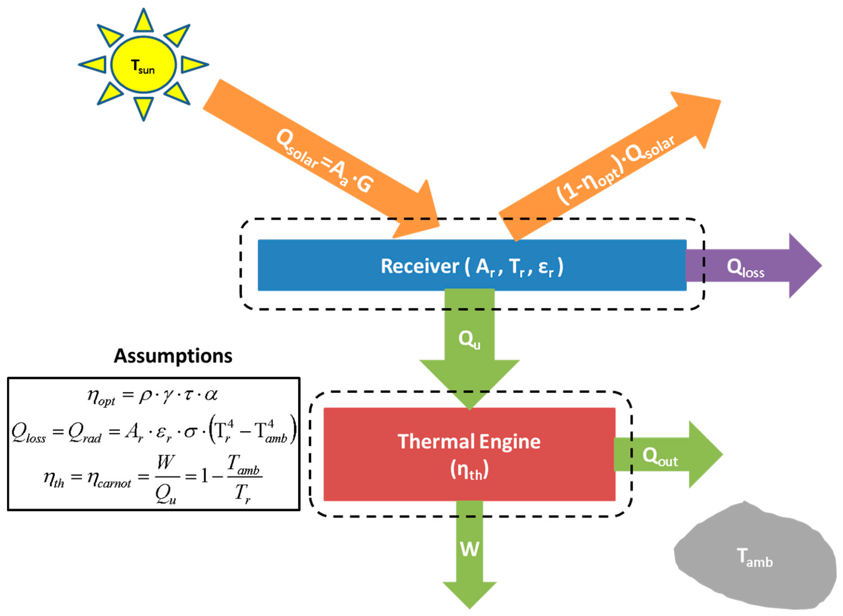
In this study, a modified model about the maximum work production from the solar energy is suggested. The suggested model does not calculate the exergy efficiency of the solar irradiation, but it gives a possible maximum limit of the work production of a coupled thermal engine to the solar collector. This model takes into consideration some important limitations of the solar thermal collectors as the optical and the thermal losses. These losses have been investigated theoretically, and the minimum possible values of these losses are investigated in order to give a possible upper limit. This model is mainly focused on solar concentrating technologies (parabolic trough collector for instance), and it includes the following parameters:
- -
- The optical efficiency of the collector (ηopt), which is the product of the receiver absorbance, the cover transmittance, the concentrator reflectance; it also includes the impact of the incident angle.
- -
- The radiation thermal losses of the receiver are taken into account using the emittance of the receiver (εr). This parameter usually takes low values (close to 0.05~0.10) for high-quality collectors. It has been assumed the collector exchanges irradiation with the ambient and not with the sky.
- -
- The solar irradiation is considered as heat and not irradiation in the model, something that is not performed in similar studies [13].
- -
- The convection losses are neglected because by using vacuum between glass cover and absorber (in parabolic trough collectors, for instance), these thermal losses become negligible. This assumption is reasonable because the present work aims to determine the maximum work extraction using a real concentrating solar collector. So, this assumption corresponds to a high quality concentrating collector. In any case, an increase in the emittance (about 0.1) can be performed in order to take into account the convection thermal losses.
Figure 1 illustrates the energy flow between the used components of the suggested model. The solar energy amount delivered to the receiver is partially absorbed due to optical losses. The receiver loses energy to the environment due to its high temperature. The useful energy obtained by the receiver is the input energy in a thermal engine, which produces useful work. This engine is assumed as a Carnot cycle in order to determine the maximum possible work extraction.
Moreover, the heat losses of the receiver are assumed to be only from radiation. The heat convection losses have been neglected, an assumption that is more common in concentrating collectors investigation in which the radiation losses play a significant role. As it has been stated above, in case the convection losses are important, an increase in the emittance can be inserted in order to simulate the real situation. It can be assumed that the receiver is inside a huge vacuum dome. This idea is close to the evacuated tubes in which the heat convection losses are close to zero. The cover of the collector, which is a huge dome, has a temperature close to the environment, and for this reason we can assume that the receiver exchanges radiation with the environment. However, the optical losses due to the cover are taken into account in the optical loss efficiency (ηopt).
3.2. Mathematical Description
The mathematical part of the analysis includes the energy balances in the receiver, in the thermal engine, and in the total system. After these steps, the system optimization is presented.
3.2.1. Energy Balance in the Receiver
The available solar energy delivered to the collector is given by Equation (8). The symbol (G) is the solar intensity that is able to be utilized by the collector. For a flat plate collector, it includes the diffuse radiation, while for an imaging concentrating collector it includes only the beam radiation. Moreover, it is essential to say that this solar intensity is assumed to be vertical to the collector aperture, so the incident angle has to be taken into consideration.
The energy balance in the receiver is presented in Equation (9), while the radiation heat losses are given by Equation (10).
At this point, it is important to state that an assumption of the present model is that the collector exchanges irradiation with the ambient temperature and not the sky temperature. This assumption is totally valid for some collectors (for instance the linear Fresnel reflector and the solar dish) or partially for others (for instance the low part of the parabolic trough collector absorber).
Equation (11) gives a general equation for optical efficiency calculation. More specifically, all the possible reasons for the optical loss are taken into consideration. The reflector reflectivity (r), the intercept factor (γ), the cover transmittance (τ), and the absorber absorbance (α) are the four products of the optical efficiency. The impact of the incident angle can be included in the intercept factor. So, the incident angle modifier impact can be modeled in the intercept factor.
The collector thermal efficiency is calculated as the ratio of the useful energy to the available solar energy to the collector aperture. Equation (12) shows this determination and simultaneously includes extra calculation steps.
The concentration ratio (C) is calculated according to Equation (13):
3.2.2. Energy Balance in the Thermal Engine
The energy balance in the thermal engine proves that the heat input is transformed to useful work and to heat losses to the environment, as Equation (14) shows:
The thermal efficiency of this thermal engine is equal to the respective Carnot engine efficiency as Equation (15) presents. The useful heat production of the solar collector is the heat input in the thermal engine, and thus this quantity is used in Equation (15).
3.2.3. Total System Energy Balance
The system efficiency is the ratio of the produced work to the available solar irradiation. It is easily proved that this parameter is the product of thermal engine efficiency and collector efficiency. By using the proper symbols, Equation (16) is the final version of the system efficiency. Parameter (X) is the ratio of the receiver temperature to the ambient temperature, according to Equation (17).
Parameter (p) is a characteristic of the collector that is dependent on its quality and the ambient conditions. Parameter (z) shows its quality; high values of this collector lead quality collector, while low values mean low quality. These quantities are determined below by Equations (18) and (19). These equations have been defined properly in order to simplify the present analysis and to present the results (and the methodology) in a brief way.
An important result of this analysis is that the optimum performance of the system is dependent on only one parameter (p). This parameter expresses the losses to the environment to the energy delivered by the sun. Small values of this parameter mean low performance due to operating conditions and design configuration.
3.2.4. Optimum Operation Temperature
In order to determine the optimum operation of the system, the first derivative of the system efficiency is calculated. This derivative is set equal to zero, according to Equation (20), the fact that means optimum operation.
The result of Equation (20) is a non-linear equation, which is given below. The optimum value for the parameter (X) is obtained by solving arithmetically the Equation (21). The Equation (21) is a result of the combination of Equations (16) and (20).
In Equation (21), there is the parameter (q), which is fully dependent on the parameter (p), according to Equation (22). The parameter (q) can be found by combing the Equations (16) and (20).
By solving Equation (21), the optimum value for the parameter (X) is determined, and the respective optimum value for the receiver temperature (Tr,opt) is calculated. By substituting the value (Xopt) in Equation (16), the maximum possible system efficiency is calculated. By knowing this parameter, the maximum work (Wmax) is calculated easily, as the product of maximum system efficiency to the available solar energy (Qsolar).
4. Results—Discussion
4.1. Solution of the Optimization Polynomial
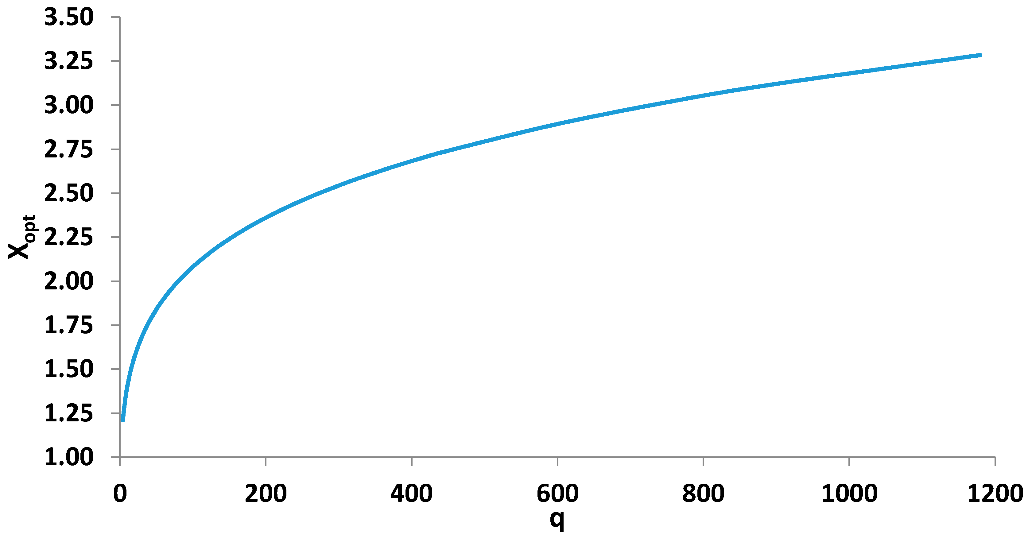
The first step in the analysis of the suggested model is the presentation of the solution of Equation (21) as a function of parameter (q). Figure 2 shows the correlation between (Xopt) and (q), for a great range of (q) values. This great range practically covers all the possible solar collectors.
By making an approximation with the least square method, Equation (23) was proved to match excellently with the curve of Figure 2.
The next step is to present the system efficiency for various values of parameter q. Figure 3 displays this relationship between these quantities. Moreover, according to Equation (16), the optical efficiency is engaged in the total system efficiency. For this reason, more curves are given, each for different value of optical efficiency. Figure 3 depicts the system efficiency for a range of values of parameter q and for optical efficiency 60%, 80%, and 100%.
4.2. Impact of Design Parameters in the System Performance
After presenting the general solution of the method, the next step is to present the impact of the collector parameters in the system performance. Specifically, the optical efficiency, the concentration ratio, and the absorber emittance were investigated. In order to make a general analysis, the rest of the parameters were kept constant. More specifically, the ambient temperature (Tamb) was selected to be 298 K, and the solar irradiation (G) was kept constant at 1000 W/m2, which are typical values for the evaluation of solar collectors. This solar irradiation corresponds to the possible irradiation utilized from every collector in every case. More specifically, in flat technologies, the examined irradiation includes both beam and diffuse parts, while in concentrating only the beam part. At this point, it is important to state that the solar irradiation value of 100 W/m2 is a high value that can be obtained close to solar noon in the summer period (for instance June or July). However, this is a typical value for the theoretical investigation of the solar thermal systems.
Figure 4 shows the system efficiency for various collectors. Each collector is characterized by the concentration ration (C), the optical efficiency (ηopt), and the absorber emittance (εr). Figure 4a–c illustrates the system efficiency, while Figure 4d–f gives the optimum receiver temperature. It is obvious that higher concentration ratio increases the system efficiency and the optimum operating temperature. Moreover, lower emittance leads to higher system efficiency and simultaneously to greater optimum temperature. The optical efficiency influences the system efficiency in a direct way, while it has the lower impact on the optimum temperature level. More specifically, lower optical efficiency causes the optimum temperature to decrease slightly, while the decrease in system efficiency is extremely great.
The next step in this analysis is the determination of the optimum operating temperature for usual collectors. Table 1 includes the basic solar collector types and their optimum receiver temperature levels, according to the presented model. It is important to state that the emittance of the flat plate collector has selected to be greater in order to take into consideration the relative high convection losses. The optical efficiency of the compound parabolic collector was selected to be lower due to lack of tracking system. On the other hand, the optical efficiency of the flat plate collector is higher than others, because there are no reflection losses. The data of Table 1 have assumed the ambient temperature equal to 298 K and the solar irradiation equal to 1000 W/m2. It is important to state that the emittance in the flat plate case is increased in order to include the heat convection losses.
It is obvious that the higher concentration ratio makes the system efficiency and the optimum operating temperature greater. For no concentrating collectors, the temperature levels of the receiver should be in the range from 400 K to 450 K, while those for concentrating collectors should be much higher. Especially for the parabolic collector, the results proved that the optimum temperature was 884 K, and for the solar dish collectors it was 1110 K. In order to achieve these high temperatures, alternative working fluids as gas working fluids (air, nitrogen, and carbon dioxide), molten salts, or liquid sodium can be used. For the no concentrating technologies, the obtained temperature levels can be achieved by using thermal oils as working fluids and high-quality collectors. Some usual thermal oils are Therminol VP-1, Dowtherm A, Sandotherm, and Syltherm 800. Moreover, it is important to state that the high-quality collectors correspond to solar collectors with low thermal losses, high optical efficiency, well-insulated structure, and generally optimized design.
4.3. The Application of the Model in a Real Solar Collector
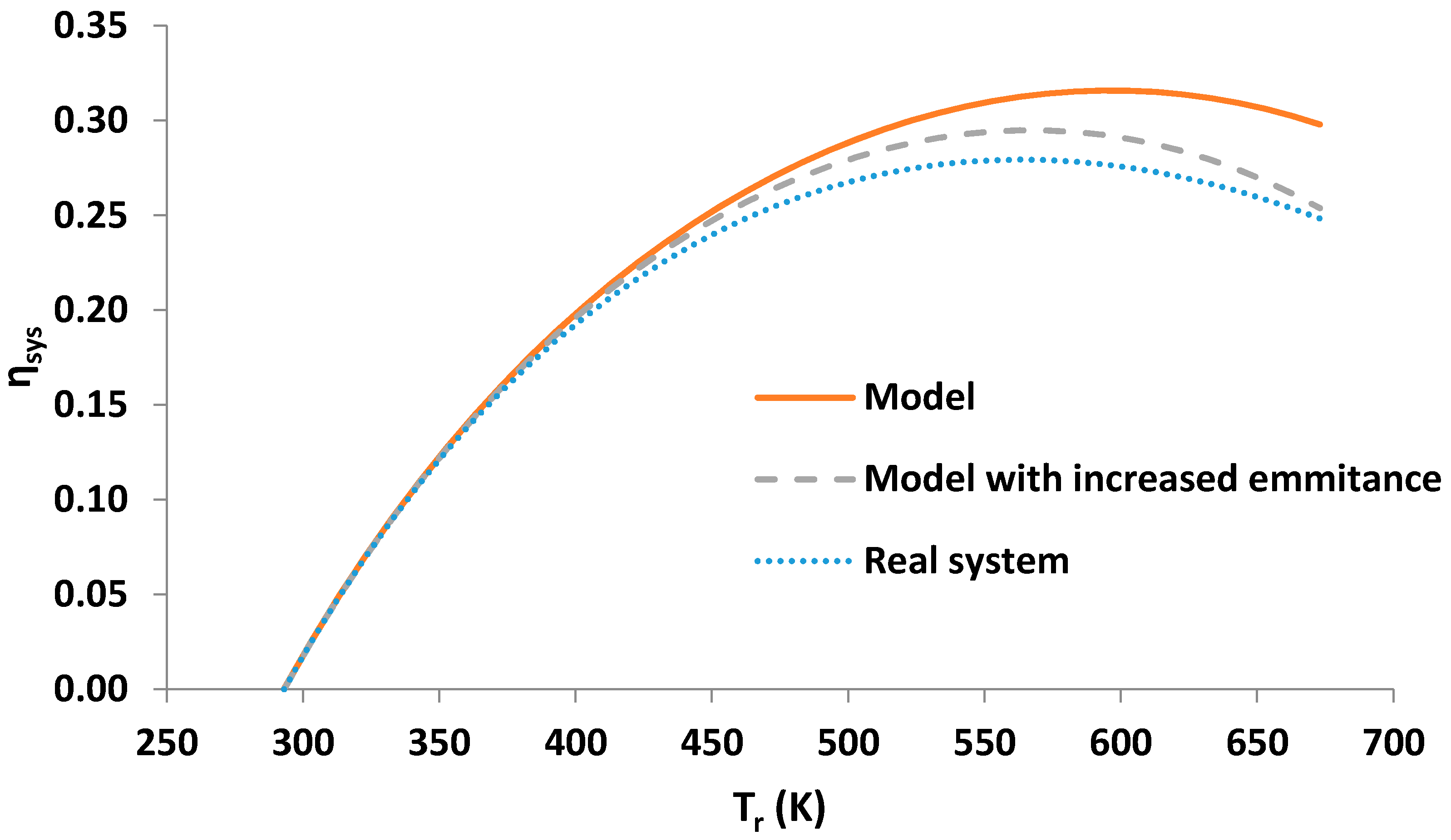
The more mature technology in concentrating solar collectors is the parabolic trough collectors. A well-established solar collector, the IST-PTC (Industrial Solar Technology Corporation product), is the examined example (Figure 5). Equation (24) gives its measured efficiency by SANDIA Reports [18,20]. This analysis is a simple validation of the developed model (Equations (16) and (23)).
It has assumed that the receiver temperature is equal to the fluid temperature in order to achieve ideal conditions, without exergy losses between the receiver and working medium. By multiplying the Equation (24) to the respective Carnot efficiency, the system efficiency can be calculated. Equation (25) presents the system efficiency using the thermal efficiency curve by SANDIA Reports. This efficiency will be called the “real system efficiency”, while the system efficiency of the suggested model will be called the “model system efficiency”.
Figure 6 gives the system efficiency as a function of the receiver temperature or the operational temperature. The curve of “real system” is calculated according to Equation (25), while the “model’’ curves according to the developed model of Equation (16). These quantities regard the system efficiency (thermal collector and thermal engine), and so they can be compared directly in Figure 6. The curves are close to each other. The model results give a greater efficiency of about 3%, in high-temperature levels. The first reason for these results is the negligence of convection heat losses in the developed model. The other reason is dependent on the temperature range that the real collector curve has been developed. More specifically, this curve can be adopted to temperature levels up to 300 °C.
The optimum temperature according to the developed model is 595 K, while according to the real system approximation the optimum temperature is about 563 K. This difference can be explained by the assumption of no convection losses in the developed model. This obstacle can be addressed by increasing the emittance by 0.1, an empirical rule. The new curve, green curve, is closer to the “real system curve” and is maximized at the same temperature (563 K). In this way, it is proved that the increase in the emittance can lead to accurate results.
Another useful comparison that can be made is between the previous optimum temperature values and the optimum temperature from Torres-Reyes model [17], according to Equation (7). The problem in this model is the need for knowledge of heat loss coefficient UL. In this case, this parameter was calculated from Equation (24), as Equation (26) shows:
The results gave optimum temperature equal to 630 K, a value that is greater enough than the real optimum. Comparing all the presented optimum temperature levels, it is obvious that this developed model leads to a better approximation of the real situation than Torres-Reyes model. It is important to state that the Reyes methodology has been found in the literature with similar other ways.
4.4. Discussion
The developed model is a new way to estimate the optimum operating temperature of a solar collector and, consequently, the maximum work extraction, based on Carnot cycle. A literature review showed that many researchers have investigated solar exergy or maximum work produced by solar energy theoretically (Petela, Jeters, Spanner, Parrot, Badescu). Other researchers, such as Torres-Reyes, performed a more realistic study that includes more parameters of the solar collectors.
The suggested model of this study takes into account the concentration ratio, the optical efficiency, the receiver emittance, and the operation conditions (ambient temperature and solar irradiation). The heat convection losses are negligible in this model, because the receiver is assumed to be inside a huge dome. However, a small increase in the emittance can be applied in order to take into consideration the convection losses, something that leads to accurate results. Moreover, in concentrating collector the convection losses have a minor influence of the thermal losses, something that enforces the main assumption of this study. Furthermore, this model takes into account the exact ambient temperature and the exact solar irradiation available in any case. A simple validation of the model and a comparison with Torres-Reyes model [17] is given in Section 4.3. The proposed increase in the emittance leads to correct optimum operating temperature determination. Moreover, the developed model is compared with the results about the IST PTC from SANDIA Reports [18,20], and the obtained results prove that the developed model is valid.
Furthermore, it can be said that the present model gives results close to the real performance of the system, while the traditional equations of (Petela, Jeters, Spanner, etc.) give extremely high values that do not correspond to the use of solar collectors. The results of Table 1 proved maximum performance up to 50% with solar dishes, while the Petela model gives 93.11%, for example. So, it is proved that the use of a model that takes into consideration the collector characteristic is important in order to perform accurate calculations.
5. Conclusions
This study presents a model for the optimum operating temperature of a solar collector in order to maximize the work produced by a coupled thermal engine. The suggested model is novel, because many collector parameters are taken into consideration and the analysis is realistic. The Carnot cycle is assumed to be the thermodynamic cycle of the thermal engine in order to take the maximum possible work output from the heat input. In every case, the optimum operating temperature is calculated in order for the maximum possible work to be achieved.
The developed model was validated for a typical parabolic collector, and the final results gave an optimum temperature close to the real one, based on literature data. An extra comparison with another literature model is given, and, finally, it is proved that the suggested model is close to the literature experimental results. Moreover, another advantage of this model is that it is able to cover a great variety of solar collectors. Concentrating and not concentrating collectors, with and without selective coating, as well as glazed and unglazed collectors, in all possible operating conditions, are included in this model. The only drawback is the negligence of the heat convection losses, something that is faced by increasing the emittance of the absorber; an assumption that is presented and analyzed also in this study. As a final conclusion, the suggested model is able to determine the optimum operating temperature of the system by taking into account the primary solar collector characteristics.
Acknowledgments
Evangelos Bellos would like to thank “Bodossaki Foundation” for its financial support.
Author Contributions
The authors of this work have the same contribution in all the parts of the present work.
Conflicts of Interest
The authors declare no conflict of interest.
Nomenclature
| A | Area, m2 |
| C | Concentration ratio, - |
| f | Geometric factor, - |
| G | Solar irradiation, W/m2 |
| p | Efficiency parameter, - |
| q | Polynomial parameter, - |
| Q | Heat or radiant energy, W |
| T | Temperature, K |
| UL | Thermal loss coefficient, W/m2 K |
| W | Work, W |
| X | Ratio of receiver temperature to ambient temperature, - |
| Z | Collector quality parameter, - |
| Greek symbols | |
| α | Absorbance, - |
| γ | Intercept factor, - |
| δ | Cone half-angle, ° |
| ε | Emittance, - |
| η | Efficiency, - |
| θ | Incident angle, ° |
| ρ | Reflectance, - |
| σ | Stefan–Boltzmann constant, [=5.67 × 10⁻⁸ W/m2 K4] |
| τ | Transmittance, - |
| Subscripts and Superscripts | |
| a | Aperture |
| amb | Ambient |
| carnot | Carnot cycle |
| coll | Collector |
| ex | exergy |
| loss | Thermal losses |
| max | Maximum |
| opt | Optimum |
| out | Output heat |
| r | Receiver |
| r,opt | Optimum receiver |
| solar | Solar energy |
| sun | Sun |
| sys | System |
| th | Thermal |
| u | Useful |
References
- Modi, A.; Kærn, M.R.; Andreasen, J.G.; Haglind, F. Thermoeconomic optimization of a Kalina cycle for a central receiver concentrating solar power plant. Energy Convers. Manag. 2016, 115, 276–287. [Google Scholar] [CrossRef] [Green Version]
- Larrouturou, F.; Caliot, C.; Flamant, G. Influence of receiver surface spectral selectivity on the solar-to-electric efficiency of a solar tower power plant. Solar Energy 2016, 130, 60–73. [Google Scholar] [CrossRef]
- Boukelia, T.E.; Mecibah, M.S.; Kumar, B.N.; Reddy, K.S. Optimization, selection and feasibility study of solar parabolic trough power plants for Algerian conditions. Energy Convers. Manag. 2015, 101, 450–459. [Google Scholar] [CrossRef]
- Yang, Y.; Wang, Z.; Xu, E.; Ma, G.; An, Q. Analysis and Optimization of the Start-up Process based on Badaling Solar Power Tower Plant. Energy Proced. 2015, 69, 1688–1695. [Google Scholar] [CrossRef]
- Guédez, R.; Topel, M.; Spelling, J.; Laumert, B. Enhancing the Profitability of Solar Tower Power Plants through Thermoeconomic Analysis Based on Multi-objective Optimization. Energy Proced. 2015, 69, 1277–1286. [Google Scholar] [CrossRef]
- Bellos, E.; Tzivanidis, C.; Korres, D.; Antonopoulos, K.A. Thermal analysis of a flat plate collector with Solidworks and determination of convection heat coefficient between water and absorber. In Proceedings of the 28th International Conference on Efficiency, Cost, Optimization, Simulation and Environmental Impact of Energy Systems, Pau, France, 29 June–3 July 2015. [Google Scholar]
- Bellos, E.; Tzivanidis, C.; Tsifis, G. Energetic, Exergetic, Economic and Environmental (4E) analysis of a solar assisted refrigeration system for various operating scenarios. Energy Convers. Manag. 2017, 148, 1055–1069. [Google Scholar] [CrossRef]
- Krüger, D.; Pandian, Y.; Hennecke, K.; Schmitz, M. Parabolic trough collector testing in the frame of the REACT project. Desalination 2008, 220, 612–618. [Google Scholar] [CrossRef]
- Tzivanidis, C.; Bellos, E.; Korres, D.; Antonopoulos, K.A.; Mitsopoulos, G. Thermal and optical efficiency investigation of a parabolic trough collector. Case Stud. Therm. Eng. 2015, 6, 223–237. [Google Scholar] [CrossRef]
- Bellos, E.; Tzivanidis, C.; Antonopoulos, K.A.; Gkinis, G. Thermal enhancement of solar parabolic trough collectors by using nanofluids and converging-diverging absorber tube. Renew. Energy 2016, 94, 213–222. [Google Scholar] [CrossRef]
- Semprini, S.; Sánchez, D.; De Pascale, A. Performance analysis of a micro gas turbine and solar dish integrated system under different solar-only and hybrid operating conditions. Solar Energy 2016, 132, 279–293. [Google Scholar] [CrossRef]
- Montes, M.J.; Rubbia, C.; Abbas, R.; Martínez-Val, J.M. A comparative analysis of configurations of linear Fresnel collectors for concentrating solar power. Energy 2014, 73, 192–203. [Google Scholar] [CrossRef]
- Petela, R. Exergy of undiluted thermal radiation. Solar Energy 2003, 74, 469–488. [Google Scholar] [CrossRef]
- Parrott, J.E. Theoretical upper limit to the conversion efficiency of solar energy. Solar Energy 1978, 21, 227–229. [Google Scholar] [CrossRef]
- Badescu, V. How much work can be extracted from a radiation reservoir? Phys. A 2014, 410, 110–119. [Google Scholar] [CrossRef]
- Bejan, A. Advanced Engineering Thermodynamics; Wiley Interscience: New York, NY, USA, 1988. [Google Scholar]
- Torres-Reyes, E.; Cervantes-de Gortari, J.G.; Ibarra-Salazar, B.A.; Picon-Nuñez, M. A design method of flat-plate solar collectors based on minimum entropy generation. Exergy Int. J. 2001, 1, 46–52. [Google Scholar] [CrossRef]
- Kalogirou, S.A. Solar thermal collectors and applications. Prog. Energy Combust. Sci. 2004, 30, 231–295. [Google Scholar] [CrossRef]
- Souliotis, M.; Quinlan, P.; Smyth, M.; Tripanagnostopoulos, Y.; Zacharopoulos, A.; Ramirez, M.; Yianoulis, P. Heat retaining integrated collector storage solar water heater with asymmetric CPC reflector. Solar Energy 2011, 85, 2474–2487. [Google Scholar] [CrossRef]
- Dudley, V.E. SANDIA, Report Test Results for Industrial Solar Technology Parabolic Trough Solar Collector; SAND94-1117; Sandia National Laboratory: Albuquerque, NM, USA, 1995.
Figure 1.
Description of the suggested model.

Figure 2.
Optimum values of parameter X for a great range of parameter q.

Figure 3.
Maximum system efficiency as a function of parameter (p) for various optical efficiency values.
Figure 3.
Maximum system efficiency as a function of parameter (p) for various optical efficiency values.
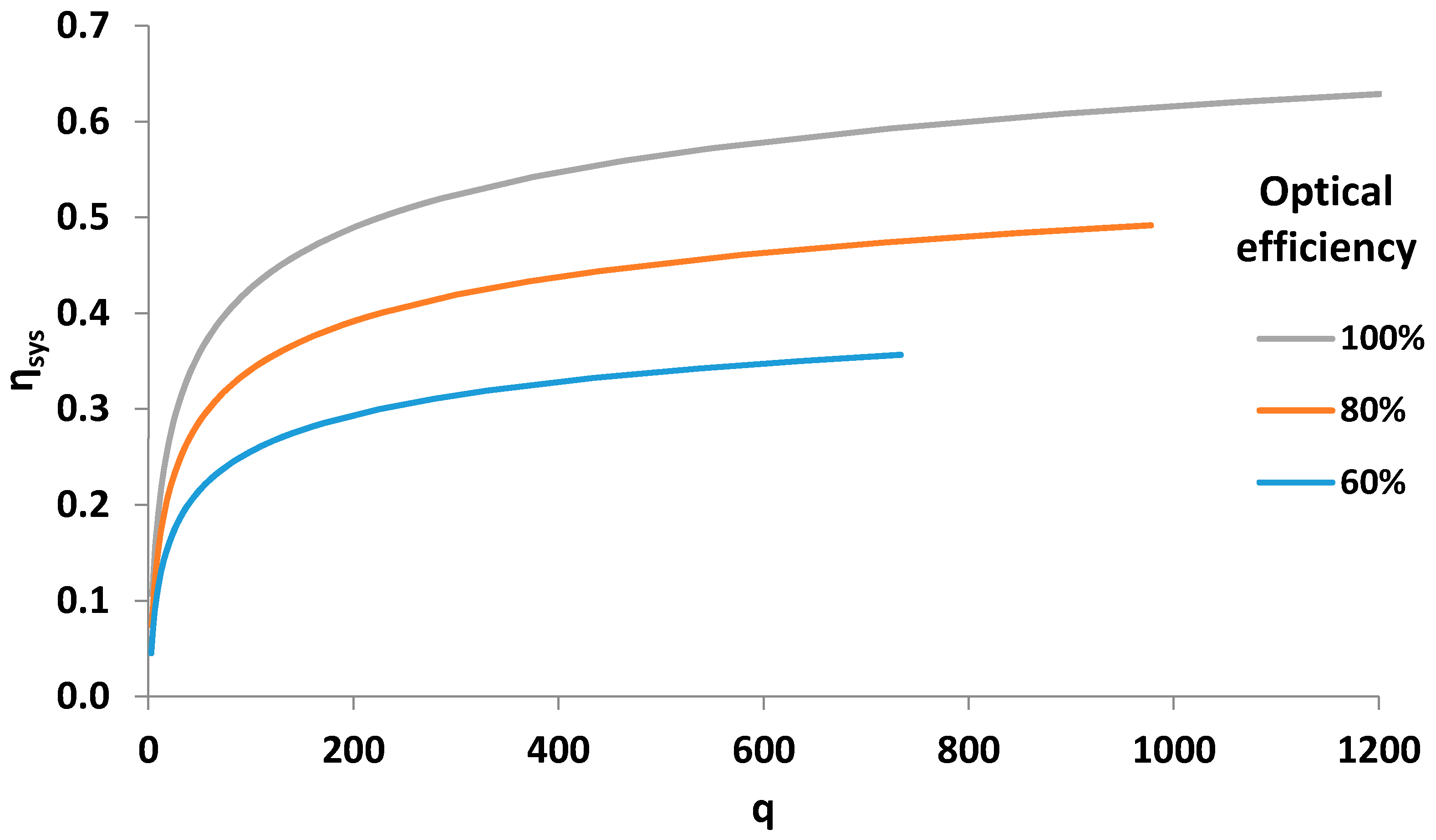
Figure 4.
Maximum system efficiency (a,b,c) and optimum receiver temperature (d,e,f) for various values of the collector parameters.
Figure 4.
Maximum system efficiency (a,b,c) and optimum receiver temperature (d,e,f) for various values of the collector parameters.
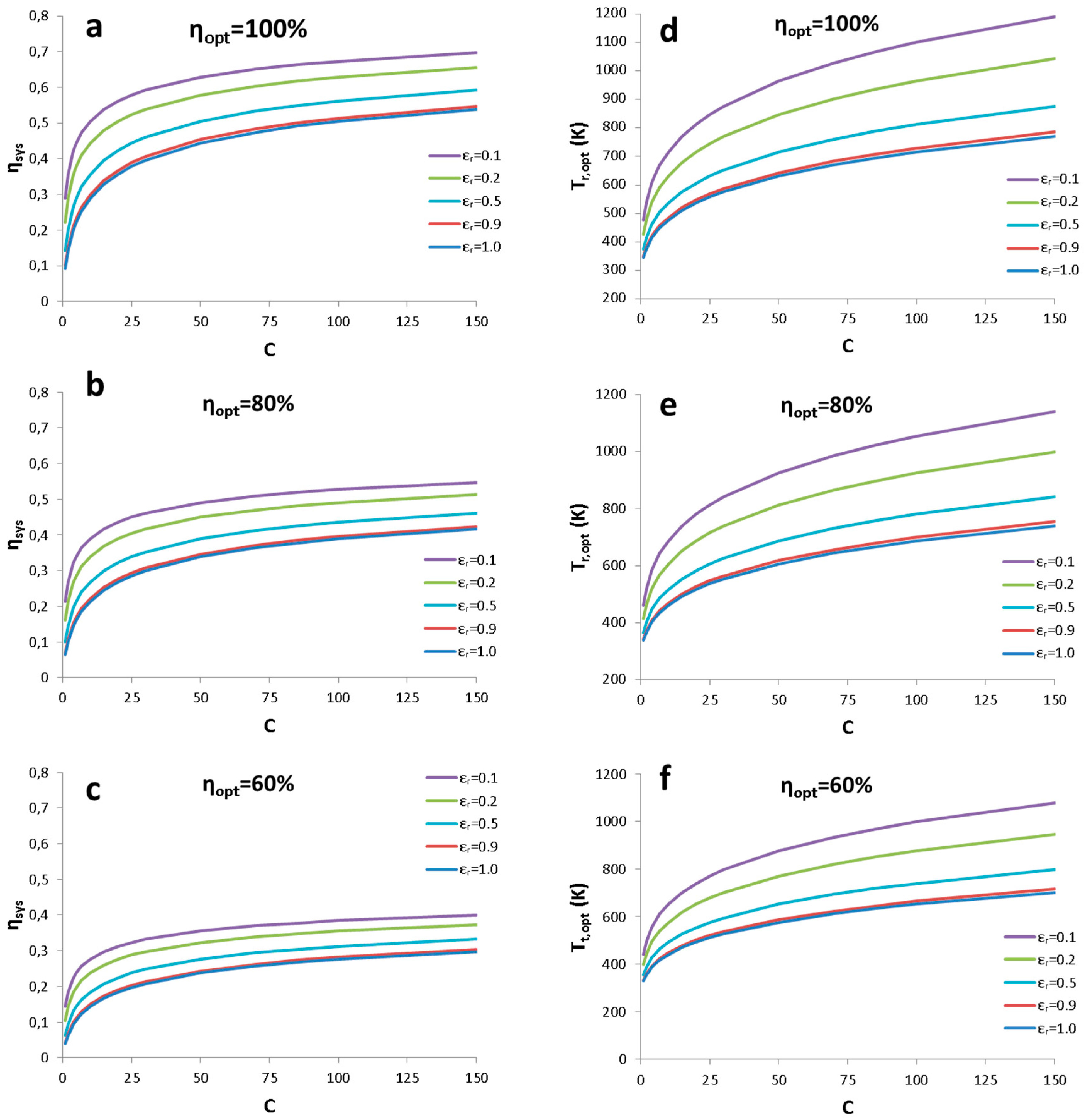
Figure 5.
Depiction of a parabolic trough collector.
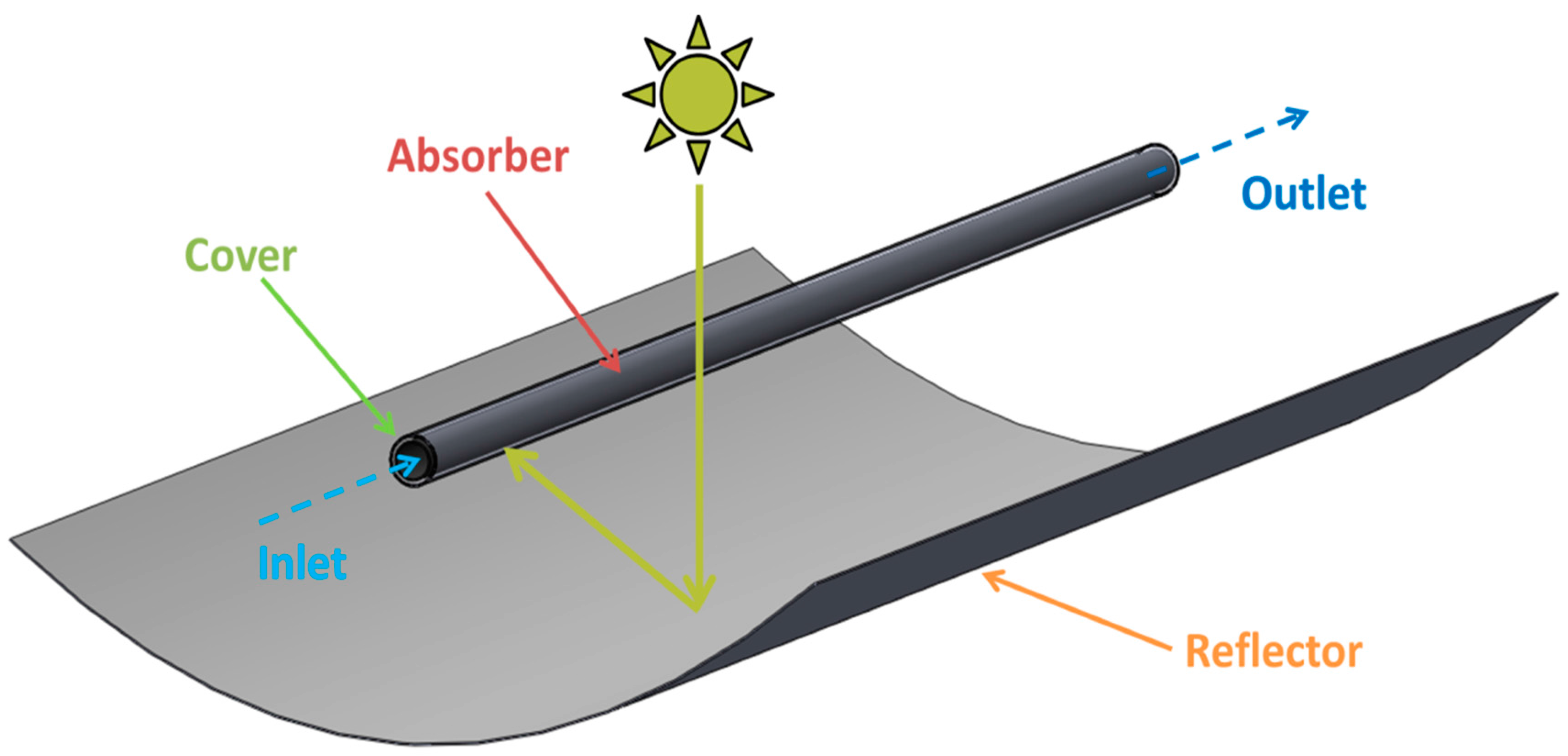
Figure 6.
Comparison between real system performance and model results.


| Collector | C | ηopt | εr | Tr,opt (K) | ηsys |
|---|---|---|---|---|---|
| Flat plate collector | 1 | 0.8 | 0.25 | 401 | 0.1449 |
| Evacuated tube collector | 1 | 0.7 | 0.10 | 451 | 0.1777 |
| Compound parabolic collector | 3 | 0.6 | 0.10 | 527 | 0.2079 |
| Parabolic trough collector | 30 | 0.75 | 0.10 | 884 | 0.4400 |
| Solar dish collector | 100 | 0.75 | 0.10 | 1110 | 0.5011 |
© 2018 by the authors. Licensee MDPI, Basel, Switzerland. This article is an open access article distributed under the terms and conditions of the Creative Commons Attribution (CC BY) license (http://creativecommons.org/licenses/by/4.0/).
Share and Cite
MDPI and ACS Style
Bellos, E.; Tzivanidis, C. A Realistic Approach of the Maximum Work Extraction from Solar Thermal Collectors. Appl. Syst. Innov. 2018, 1, 6. https://doi.org/10.3390/asi1010006
AMA Style
Bellos E, Tzivanidis C. A Realistic Approach of the Maximum Work Extraction from Solar Thermal Collectors. Applied System Innovation. 2018; 1(1):6. https://doi.org/10.3390/asi1010006
Chicago/Turabian StyleBellos, Evangelos, and Christos Tzivanidis. 2018. "A Realistic Approach of the Maximum Work Extraction from Solar Thermal Collectors" Applied System Innovation 1, no. 1: 6. https://doi.org/10.3390/asi1010006