Improvement of the Multi-Hierarchy Simulation Model Based on the Real-Space Decomposition Method


1
National Institute for Fusion Science, National Institutes of Natural Sciences, Toki, Gifu 509-5292, Japan
2
Department of Fusion Science, SOKENDAI (The Graduate University for Advanced Studies), Toki, Gifu 509-5292, Japan
3
National Institute of Information and Communications Technology, Koganei, Tokyo 184-8795, Japan
*
Author to whom correspondence should be addressed.
Plasma 2018, 1(1), 90-104; https://doi.org/10.3390/plasma1010009
Submission received: 1 March 2018
/
Revised: 23 April 2018
/
Accepted: 25 April 2018
/
Published: 27 April 2018
(This article belongs to the Special Issue Multiscale Methods in Plasma Physics)
Abstract
:Multi-hierarchy simulation models aimed at analysis of magnetic reconnection were developed. Based on the real-space decomposition method, the simulation domain consists of three parts: a magnetohydrodynamics (MHD) domain, a particle-in-cell (PIC) domain, and an interface domain to communicate MHD and PIC data. In this paper, the previous model (the 1D interlocking with the upstream condition) by the authors is improved to three types of new models, i.e., two types of the 1D interlocking with the downstream condition and one type of the 2D interlocking with the upstream condition. For their verification, simulations of plasma propagation across the multiple domains were performed in the multi-hierarchy models, and it was confirmed that the new interlocking methods are physically correct.

1. Introduction
Magnetic reconnection is a ubiquitous process in which stored magnetic energy is converted to plasma kinetic and thermal energies [1]. In fusion plasmas, magnetic reconnection is thought to be strongly related to tokamak disruptions [2], in which energy stored in the core is released to the periphery region. For the stable operation of fusion devices, the disruption needs to be controlled. Considering the astrophysical field, magnetic reconnection is thought to play an essential role in the disturbances in the Earth’s magnetosphere, i.e., magnetospheric substorms [3]. When magnetic reconnection occurs somewhere in the current sheet of the night-side, plasma outflows and plasmoids are generated. It is believed that the plasma particles injected into the ionosphere cause auroras in the polar region.
For many years, magnetic reconnection has been one of the most interesting topics actively investigated by means of theory, laboratory experiments, satellite observations, and numerical simulations [1]. The reconnection studies have advanced significantly, but the full picture of magnetic reconnection is not yet understood. This is because magnetic reconnection is a multi-hierarchy phenomenon with multiple spatial and temporal scales. Some kinetic physics originating from chaotic motions of individual plasma particles are a trigger of magnetic reconnection, while the global structure of the magnetic field changes and the stored energy is dynamically released through magnetic reconnection. For a complete understanding of magnetic reconnection as a multi-hierarchy process, it is necessary to self-consistently and simultaneously treat microscopic physics with electron motion scales and macroscopic dynamics with large scales covering the entire system. Such simulation models are called “multi-hierarchy models”.
Multi-hierarchy models are divided into two types of models depending on the interlocking methods. One is a model based on the coarse-graining method, and the other is a model based on the real-space decomposition method. In the coarse-graining method, first, complicated kinetic phenomena are demonstrated by using tools of microscopic simulation such as particle simulation. Next, the kinetic effects on the global dynamics are modeled under some assumptions or conditions and are expressed as parameters or macroscopic quantities which are incorporated into global fluid equations. For example, Horiuchi et al. modeled the electric resistivity (the reconnection electric field), which is originated from kinetic processes, based on the assumption that magnetic reconnection was under the steady state [4]. Kuznetsova et al. also modeled the electric resistivity (the reconnection electric field) based on different assumptions [5]. These different types of modeled resistivity were incorporated into the magnetohydrodynamics (MHD) basic equations to simulate magnetic reconnection in the Earth’s magnetosphere. However, the coarse-graining method has the disadvantage that the range of its application is inevitably limited, so long as some assumptions or conditions are used for the modeling. In contrast, in the real-space decomposition method, kinetic effects are directly incorporated into macroscopic simulations without assumptions or conditions. For example, Sugiyama and Kusano developed a multi-hierarchy model interlocking a Hall-MHD code and a hybrid code (electron: fluid; ion: particle) and applied this model to shock waves [6]. For application to magnetic reconnection, Makwana et al. coupled a Hall-MHD code and a semi-implicit particle-in-cell (PIC) code [7]. Usami et al. interlocked an MHD code and an explicit PIC code [8].
Let us explain our multi-hierarchy model based on the real-space decomposition method. As described above, the real-space in the simulation is divided into multiple domains, i.e., the MHD, PIC, and interface domains. The dynamics in the MHD domain are solved by means of MHD simulations, and the physics in the PIC domain are calculated by using the PIC code named “PASMO” [9,10,11]. The interface domain is located between the MHD and PIC domains to communicate the MHD and PIC data. Here, let us emphasize that the interface domain does not force the connection of the MHD and PIC domains. In the interface domain (of course, in the MHD domain), MHD conditions such as the Maxwellian velocity distribution and the frozen-in constraint are fully satisfied. In other words, if an MHD condition is clearly violated in the interface domain, the location of the interface domain is not appropriate. The PIC domain needs to be elongated and the positions of the interface and MHD domains must be displaced.
To examine the physical reliabilities of hierarchy-interlocking in the developed multi-hierarchy model, we performed some simulations by using the multi-hierarchy model. First, we simulated the propagation of linear Alfvén waves [12]. Second, we performed simulations of plasma flow injection from the MHD domain to the PIC domain [13,14]. After these two kinds of examination simulations, we applied our multi-hierarchy model to magnetic reconnection [15,16]. In 2013, we further implemented non-uniform grid points to the MHD domain in our multi-hierarchy model [17]. In 2014, we reported the influence of global plasma inflows on the physics of magnetic reconnection by using our multi-hierarchy model [8]. In addition, we installed the Adaptive Mesh Refinement (AMR) to the MHD domain in our multi-hierarchy model and demonstrated the propagation of linear Alfvén waves [18] and the driving of magnetic reconnection [19].
In this paper, we demonstrate the recent improvement of our multi-hierarchy model to apply it to a global system of magnetic reconnection such as the entire Earth magnetosphere in the near future. In Section 2, we review the interlocking scheme between the macroscopic hierarchy (the MHD domain) and the microscopic hierarchy (the PIC domain). In Section 3, we introduce three types of new multi-hierarchy models. We name them “The Improved Multi-Hierarchy Models 1, 2, and 3”, respectively, and demonstrate simulation results for confirming their reliabilities. Section 4 provides a summary of this work and discusses the future plan.
2. Overview of Hierarchy-Interlocking
In our previous works, we connected the MHD and PIC domains one-dimensionally along the upstream direction and performed simulations of magnetic reconnection. Here, we define the upstream and downstream directions as the inflow and outflow directions in magnetic reconnection, respectively. Thus, when a plasma flows into the kinetic region (the PIC domain), the inflow direction is defined as the upstream direction, and, when a plasma flows from the kinetic region (the PIC domain), the outflow direction is defined as the downstream direction. In this section, let us overview the interlocking scheme in the interface domain in the upstream direction, which is taken to be y-axis. We employ the hand-shake scheme [6,8,14,17,20] for a macroscopic quantity :
where is the macroscopic quantity derived only by using the basic equations of the MHD simulation and is the macroscopic quantity obtained only by using the basic equations of the PIC simulation. The interconnection function F is a function of the coordinate y (the upstream direction). We use
where and denote the boundaries on the MHD and PIC sides in the interface domain, respectively. It is noted that the shape of F has no physical meanings. The interface domain is located in an area where the MHD condition is fully satisfied. Thus, would be equal to , if the number of particles in the PIC simulation were infinity. However, is not completely equal to , which contains noise. The interconnection function F is used for not directly propagating noise generated in the PIC domain to the MHD domain. From empirical laws, we consider that Equation (2) is suitable for this purpose. However, if Equation (2) were used for the pressure (the thermal velocity), an unphysical heating or cooling would occur owing to the accumulation of the thermal velocity error originating from measurements and reproductions that were repeated numerous times as described below. For details, see Appendix A of Ref. [17]. To prevent the unphysical heating or cooling, only for the pressure, a different function
is used.
To calculate the physics in the interface domain, microscopic quantities such as positions and velocities of individual particles also are needed. At every PIC time step, all the particles in the interface domain are removed and are freshly loaded with particle velocities and positions which satisfy the pressure, the density, and the fluid velocity determined by the hand-shake scheme shown in Equation (1). As described above, it is assumed that a shifted Maxwellian velocity distribution holds in the interface domain in order to bridge the large gap in the degree of freedom between the MHD and PIC data. This procedure is repeated numerous times during the performance of the multi-hierarchy simulation.
Lastly, let us state that the unit transformation is necessary, since normalization constants in the MHD and PIC simulations are completely different from each other. For detailed information on the unit transformation, refer to Appendix B of Ref. [17]. Throughout this paper, we use the PIC unit system for simulation results.
3. Improved Multi-Hierarchy Models and Simulation Results
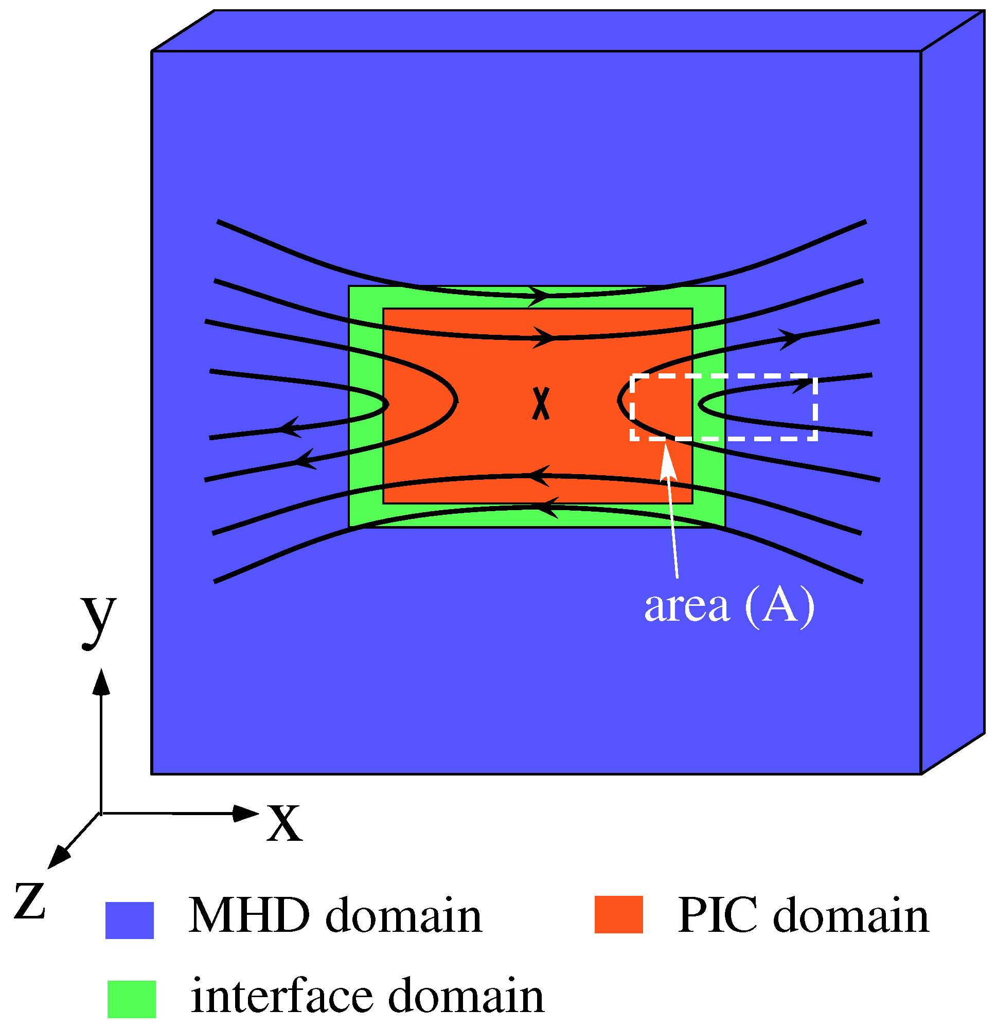
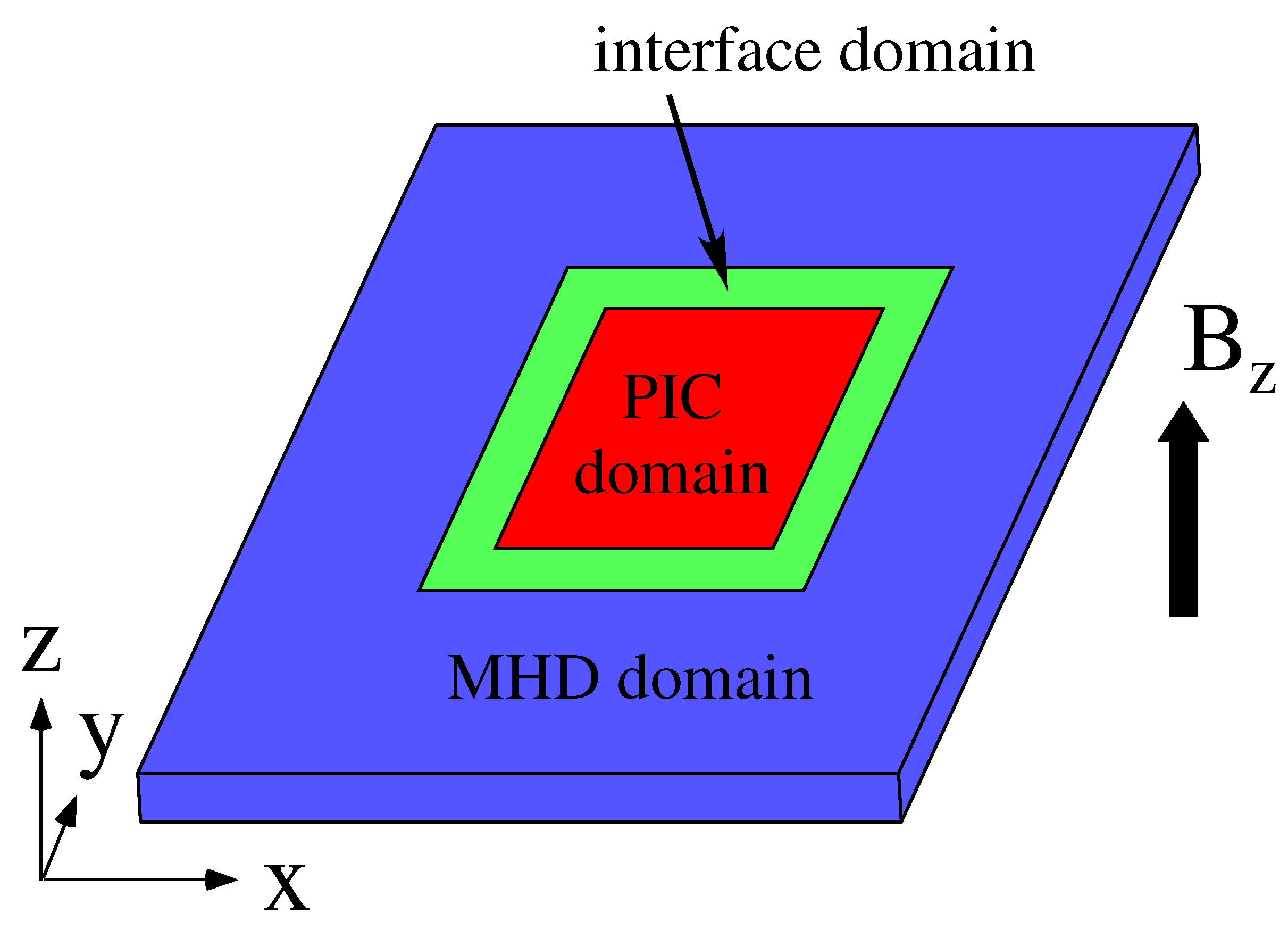
We aim at applying our multi-hierarchy model to a global system of magnetic reconnection. Kinetic simulations, such as particle simulations, require immense computer resources, and thus the size of the PIC domain in a multi-hierarchy simulation should be the requisite minimum. Thus, the interconnection between the MHD and PIC domains is required not only in the upstream direction, as described in Section 2, but also in the downstream direction. Figure 1 highlights an idealized form of the multi-hierarchy model applied to magnetic reconnection. In this model, the PIC domain is located on the central region and covers the kinetic region including the reconnection point. Surrounding the PIC domain is the MHD domain, and the interface domain is inserted between the PIC and MHD domains. The MHD and PIC domains are interlocked in both upstream (y-axis) and downstream (x-axis) directions.
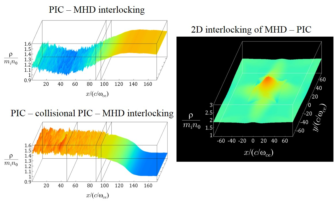
At the present stage in achieving the idealized model shown in Figure 1, we extend our multi-hierarchy model to three new models named “The Improved Multi-Hierarchy Models 1, 2, and 3”. The Improved Multi-Hierarchy Models 1 and 2 mimic the downstream region of magnetic reconnection and one-dimensionally interlock hierarchies. In The Improved Multi-Hierarchy Model 1, the two hierarchies, the PIC and MHD domains, are coupled, while, in The Improved Multi-Hierarchy Model 2, the three hierarchies, the PIC, collisional PIC, and MHD domains, are coupled. Models 1 and 2 can be regarded to correspond to the area (A) represented by the white dotted lines in Figure 1. In these models, the propagations of plasmas from the PIC domain to the MHD domain are simulated. The Improved Multi-Hierarchy Model 3 is a model which couples hierarchies two-dimensionally, namely in the two-directional scheme. The upstream condition, however, is used in the two directions. In this model, the propagation of plasmas from the MHD domain to the PIC domain is simulated.
3.1. Plasma Ejection from the PIC Domain to the MHD Domain
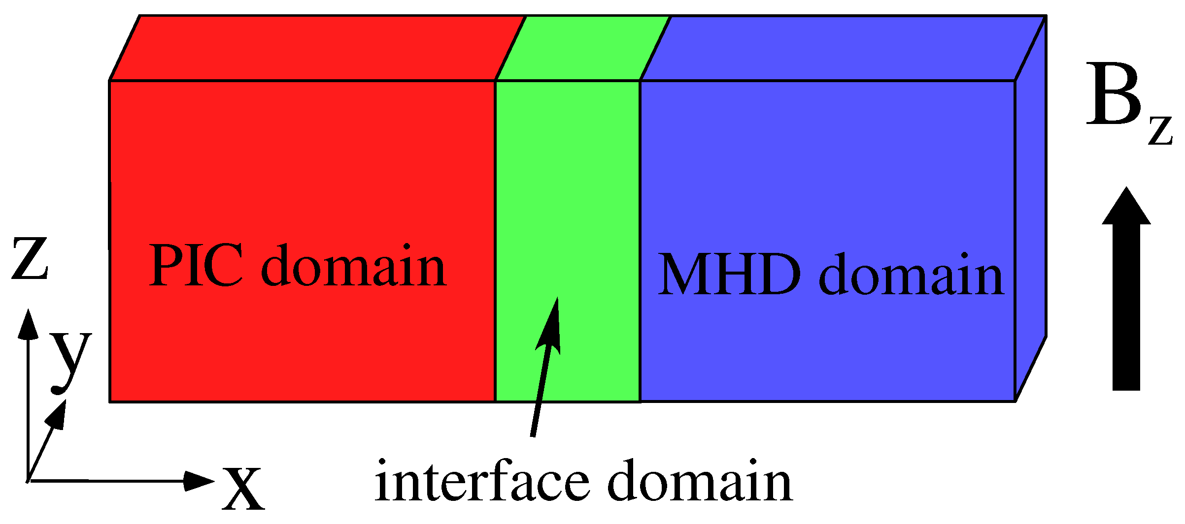
In the downstream of magnetic reconnection, the direction of main plasma flow is from the PIC domain to the MHD domain. As the first step of the hierarchy-interlocking in the downstream region, we develop a new multi-hierarchy model based on one-directional interlocking between the PIC and MHD domains. Figure 2 shows a new simulation model named “The Improved Multi-Hierarchy Model 1”. The left region is the PIC domain and the right region is the MHD domain. Between the PIC and MHD domains, the interface domain with a finite width is inserted.
Let us argue an interlocking scheme between MHD and PIC data in the interface domain in the case of the downstream direction. For the hierarchy-interlocking along the downstream direction, which is taken to be x-axis, we also use the hand-shake scheme with the same form as Equation (1):
and employ the interconnection function with the same form as Equation (2):
where and denote the boundaries on the MHD and PIC sides in the interface domain, respectively. For the pressure, Equation (5) is not appropriate, because the use of Equation (5) causes the unphysical heating or cooling. However, if instead of Equation (5), for and for were used as in the upstream direction, the information could not propagate from the PIC domain to the MHD domain. Thus, for the pressure, we adopt a new scheme, in which Equation (5) is employed as the interconnection function, but the hand-shake scheme for the pressure is modified as follows:
where is the grid spacing and N is a positive integer, assuming that the MHD domain is located at the right side of the PIC domain. This means that the pressure at is the interpolated value between at and at the so-called upwind position compared with . This modified scheme results in a successful propagation of the pressure data from the PIC domain to the MHD domain without the unphysical heating or cooling.
In the multi-hierarchy model based on the above scheme, we perform simulations of plasma ejection from the PIC domain to the MHD domain. The simulation domain is implemented on (1376, 4, 16) grid points and the box size is , where is the electron plasma frequency and c is the speed of light. The PIC domain covers the area , the interface domain is located in the area , and the MHD domain occupies the area . The uniform magnetic field is taken to be in the z direction. The system is periodic in the y and z directions and is free in the x direction.
The simulation parameters are as follows. The ion-to-electron mass ratio is , and the ratio of the electron plasma frequency to the electron gyrofrequency is . As the initial condition, the plasma density is uniform, and the ion-to-electron temperature ratio is (the thermal speed of electrons and ions are and , respectively.). In addition, initially, the Maxwellian velocity distribution is satisfied in the whole region of the PIC and interface domains. The number of ions (electrons) is initially 1,500,000, and increases to ≃2.1 ×. The number of particles per species per cell is ≃61 initially, and increases to ≃85. Here, we choose in Equation (6).
A plasma is supplied into the simulation domain from the left-side boundary of the PIC domain owing to the drift. The velocity distribution of the supplied plasma also satisfies a shifted Maxwellian distribution with the thermal speed equal to the initial thermal speed. To generate the plasma flow due to drift, an external driving electric field is imposed in the y direction at . The field is set to be zero at the initial time, and gradually grows to reach a constant value . After reaching , is gradually decreased to return to zero, so that the density of the supplied plasma is decreased.
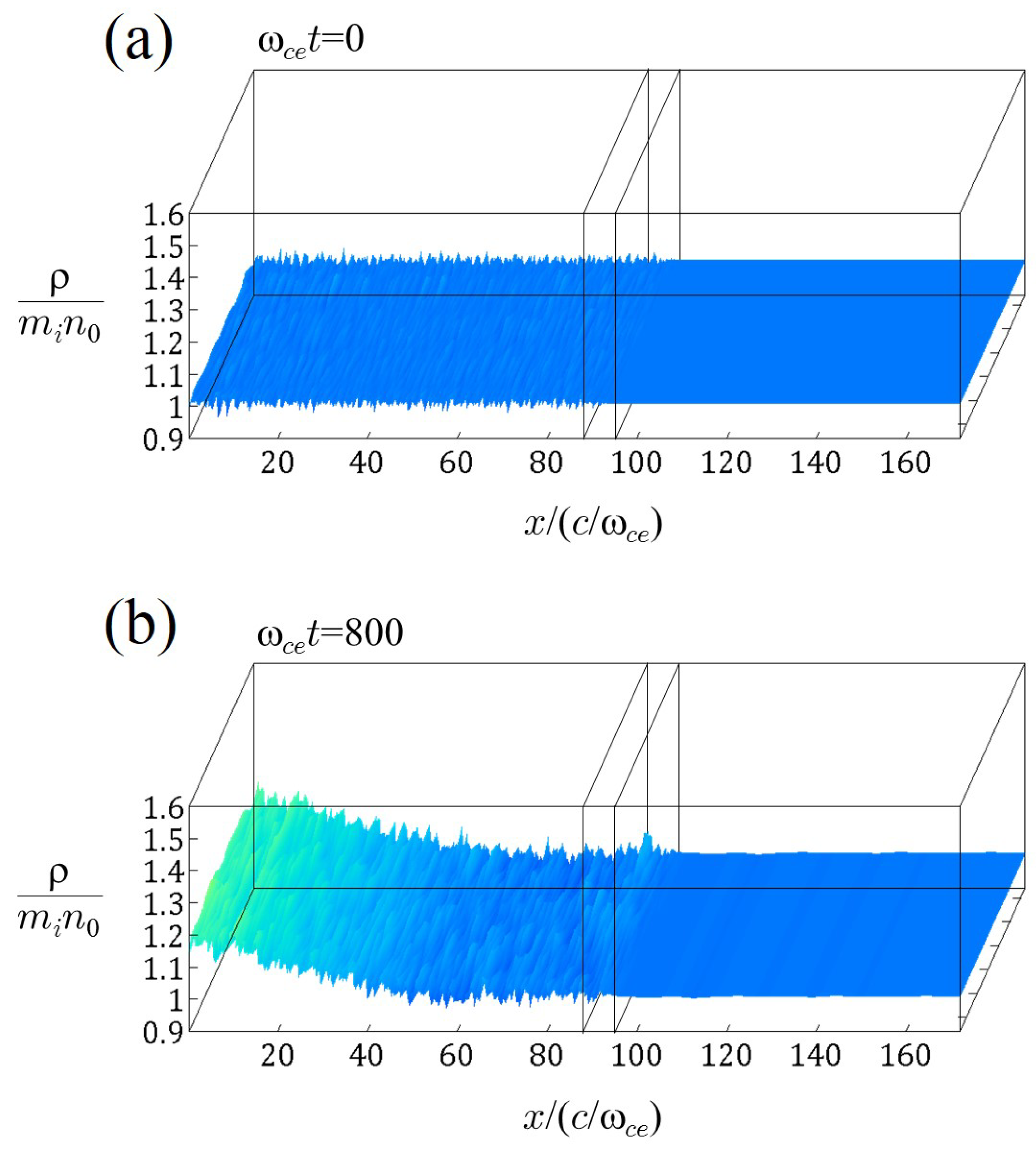
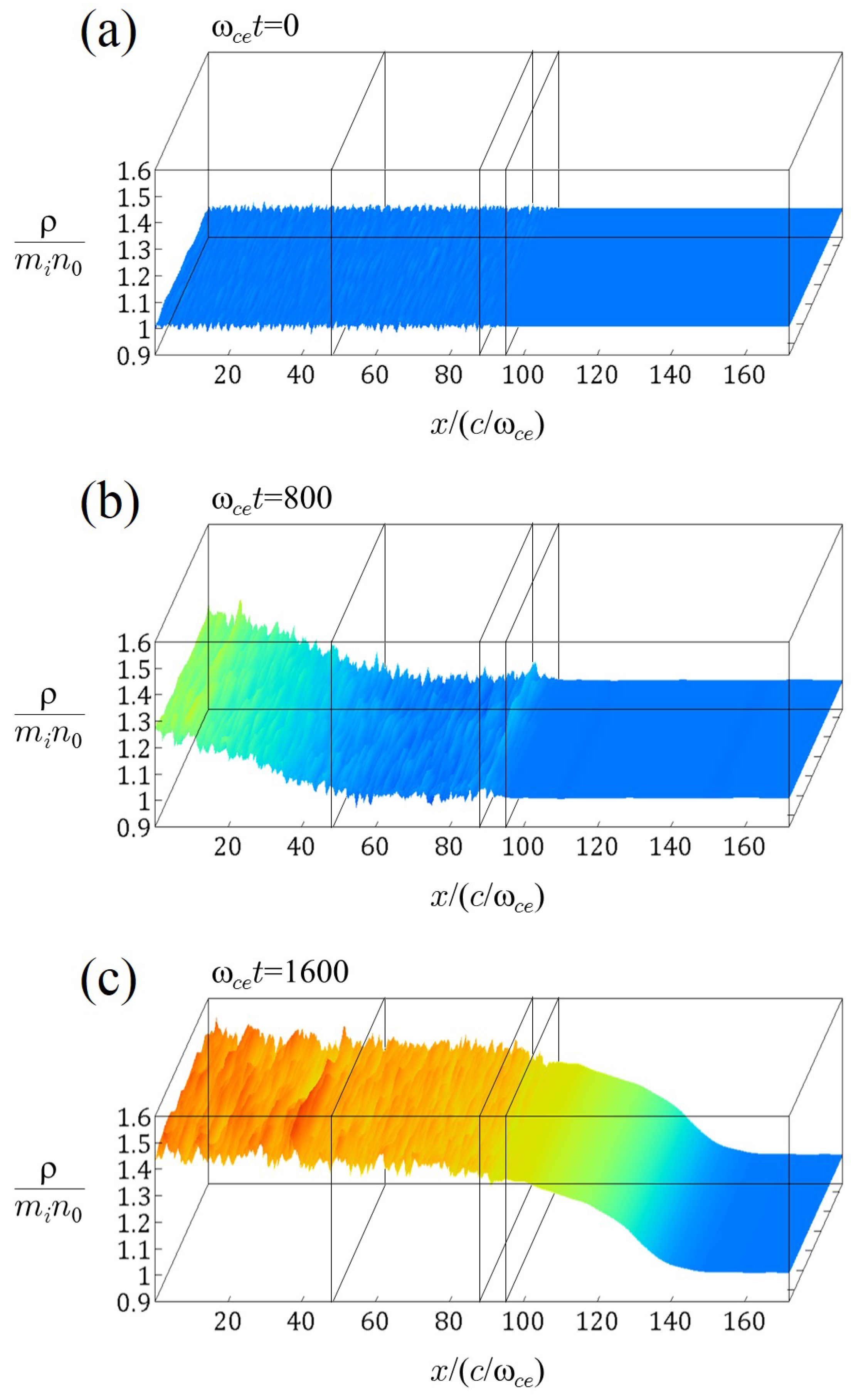
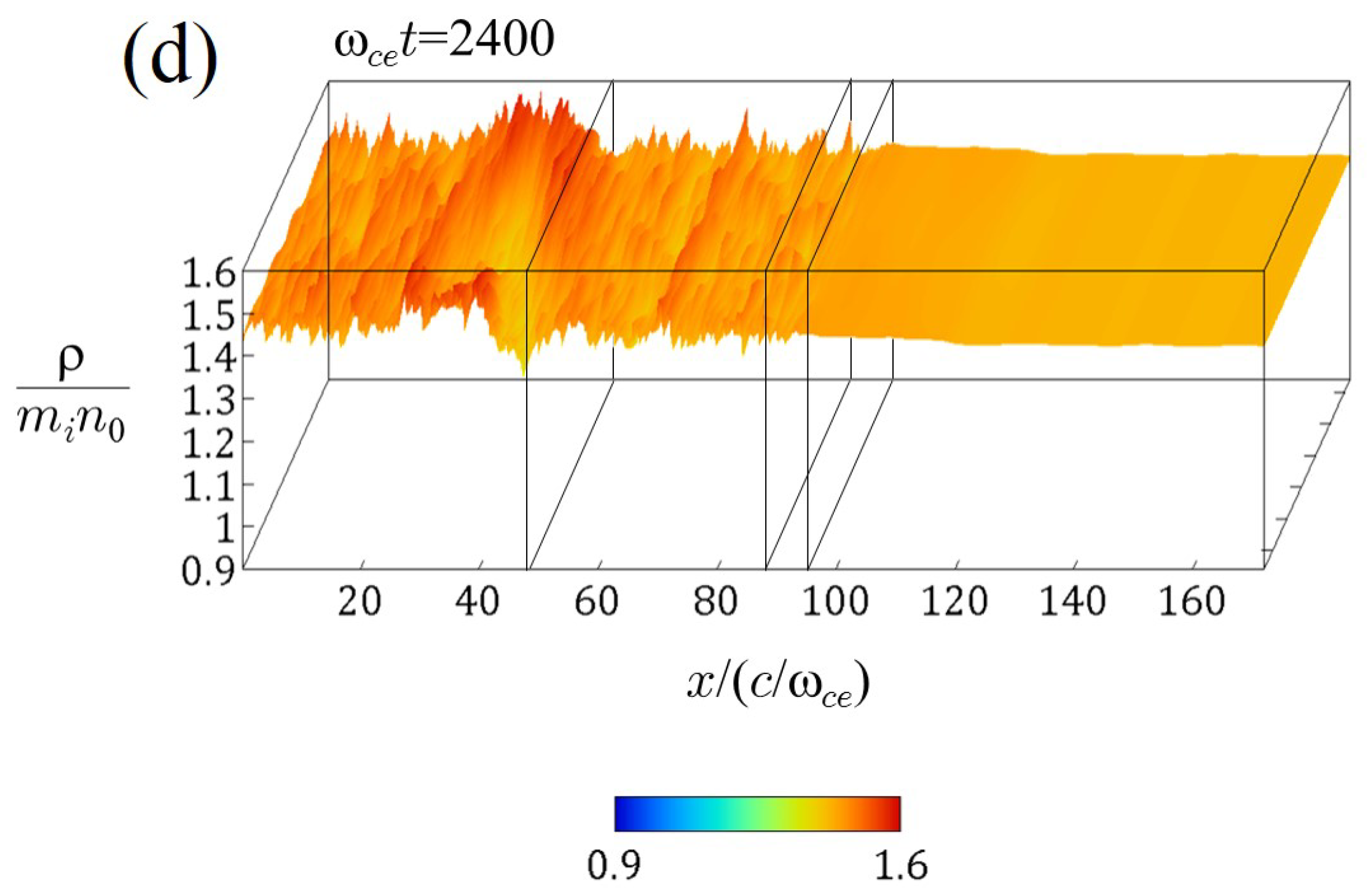
In Figure 3, we show the spatial profiles of the plasma mass density in plane at: (a) ; (b) 800; (c) 1600; and (d) 2400. The profiles are enlarged in the z-axis compared with the actual length. Only the region is displayed, since the plasma behaviors in of the MHD domain are trivial. In the panels, the colors also indicate the value of the plasma mass density as the height. The mass density is normalized to , where is the initial number density. At the initial state, holds in the whole region, where is the contribution of the electron mass, and small fluctuations are seen only in the PIC and interface domains. At , the density in the left part of the PIC domain begins to increase, and at , the plasma is smoothly and continuously propagating to the MHD domain through the interface domain. After that, the density of the plasma supplied from has been decreased at . It is confirmed that the information of the decrease in the density can transmit from the PIC domain to the MHD domain.
3.2. Plasma Ejection in the Three-Hierarchy-Interlocking Model
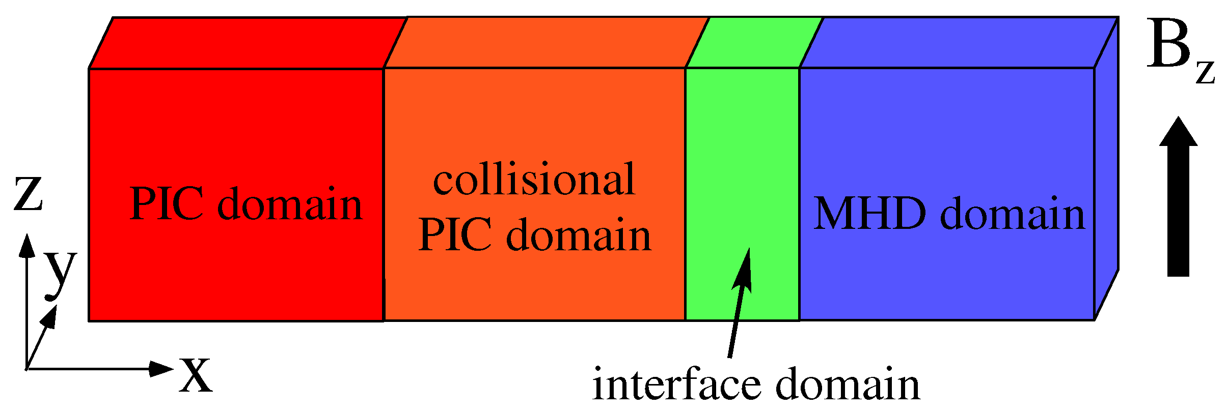
As the second step of the hierarchy-interlocking in the downstream region, we further extend our multi-hierarchy model to create a new model based on three-hierarchy-interlocking. In Figure 4, we show the schematic diagram of “The Improved Multi-Hierarchy Model 2”, in which the PIC, collisional PIC, and MHD domains are coupled. For the Coulomb collision process in the collisional PIC domain, a Monte Carlo model created by Takizuka and Abe in 1977 [21] is used. In this collision model, binary collisions of individual particles are calculated. Let us note that the interface domain is located between the collisional PIC and MHD domains, whereas there is no interface domain between the PIC and collisional PIC domains.
By using the above three-hierarchy-interlocking model, we perform simulations of plasma ejection from the PIC domain to the MHD domain via the collisional PIC domain. The simulation domain is implemented on (1376, 4, 16) grid points and the box size is . The PIC domain, the collisional PIC domain, the interface domain, and the MHD domain cover the areas of , , , and , respectively. The uniform magnetic field exists in the z direction. The boundary is periodic in the y and z directions and is free in the x direction.
The simulation parameters are the same as those used in Section 3.1, with the exception of the number of particles and the collision parameter. Initially, the number of ions (electrons) is 2,000,000 and the number of particles per species per cell is ≃81. The number of ions (electrons) increases to ≃2.9 and the number of particles per species per cell increases to ≃117. We set the collision parameter so that the ion mean free pass is ≃6 . (In the collision model by Takizuka and Abe, the Coulomb logarithm is regarded as an artificial parameter.)
As in the simulations shown in Section 3.1, a plasma is supplied into the simulation domain from the left-side boundary of the PIC domain by the imposing of in the y direction at . The electron velocity distribution of the supplied plasma satisfies a shifted Maxwellian distribution with the thermal speed equal to the initial thermal speed (), but the ion velocity distribution does not satisfy a shifted Maxwellian distribution. Regarding the direction parallel to the magnetic field (the z direction), we take the ion velocities of the supplied plasmas to not satisfy a single Maxwellian distribution, since the Maxwellian velocity distribution is generally violated in the downstream of magnetic reconnection. In this simulation, the ions are taken to be two oppositely-directed streams with the averaged velocities . The ion parallel velocity distribution is expressed as
The two streams of ions have the same thermal velocity and the same number density as the other. In the simulation shown below, we take that and . In contrast, the perpendicular velocities and of the supplied ions satisfy a shifted Maxwellian distribution with the thermal speed equal to the initial ion thermal velocity (). The x-axis is the direction of plasma propagation, and thus the distribution is a shifted Maxwellian with a finite averaged velocity, but the distribution is a Maxwellian with the zero averaged velocity.
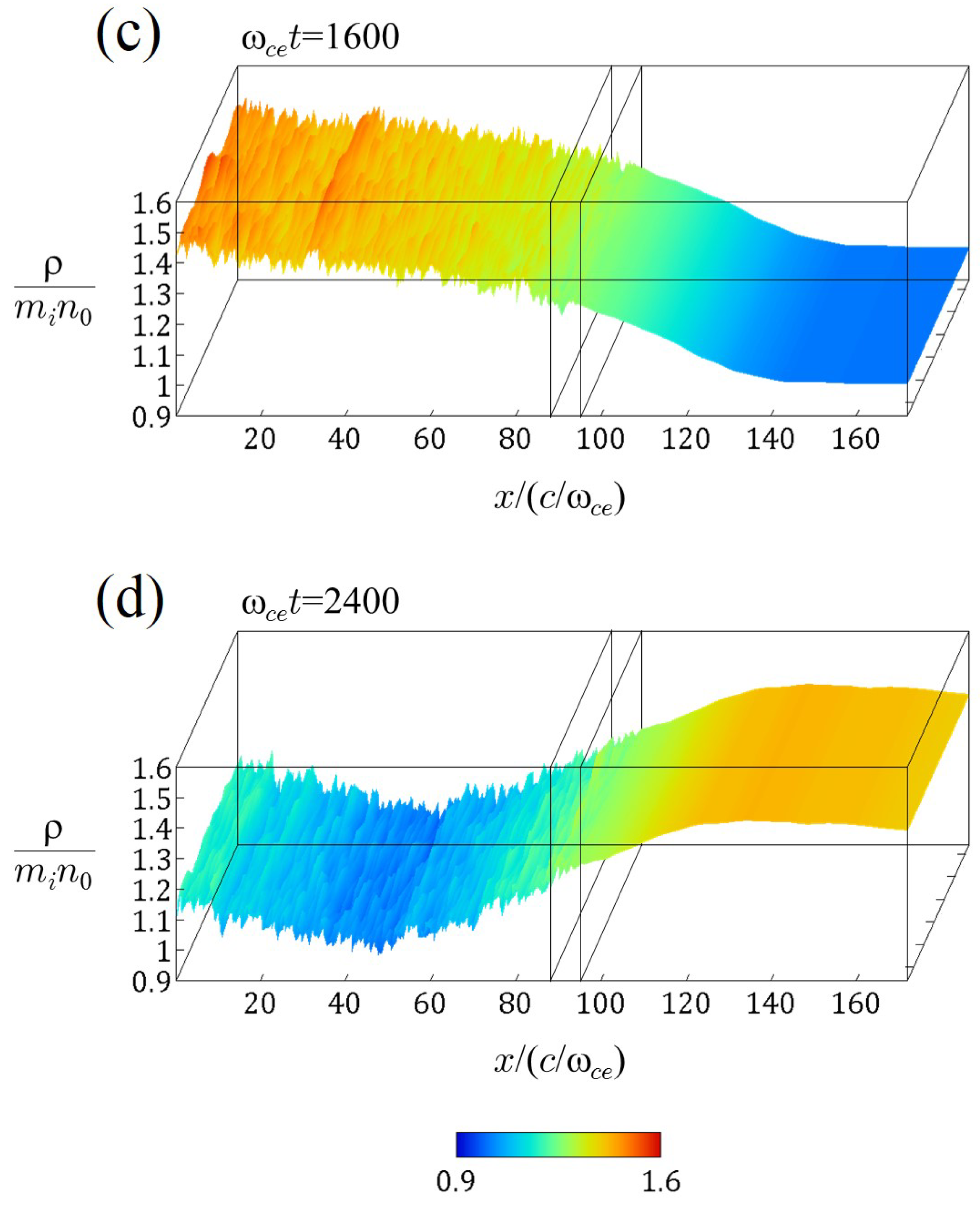
Figure 5 shows the spatial profiles of the plasma mass density in the plane at: (a) ; (b) 800; (c) 1600; and (d) 2400. As in Figure 3, the profiles are enlarged in the z-axis, only the region is displayed, and the colors and the height indicate the value of . Initially, the plasma density is uniform, and small fluctuations exist only in the PIC, collisional PIC, and interface domains. At , the plasma supplied from the left-side boundary begins to enter the collisional PIC domain. Furthermore, the plasma smoothly and continuously propagates to the MHD domain via the interface domain at . We can see that a density variation in the z direction is excited in the PIC domain. This density variation likely originates from the two streams of ions supplied from the left-side boundary. At , the density variation is intensified. However, the density variation disappears in the collisional PIC domain and thus does not transmit to the MHD domain.
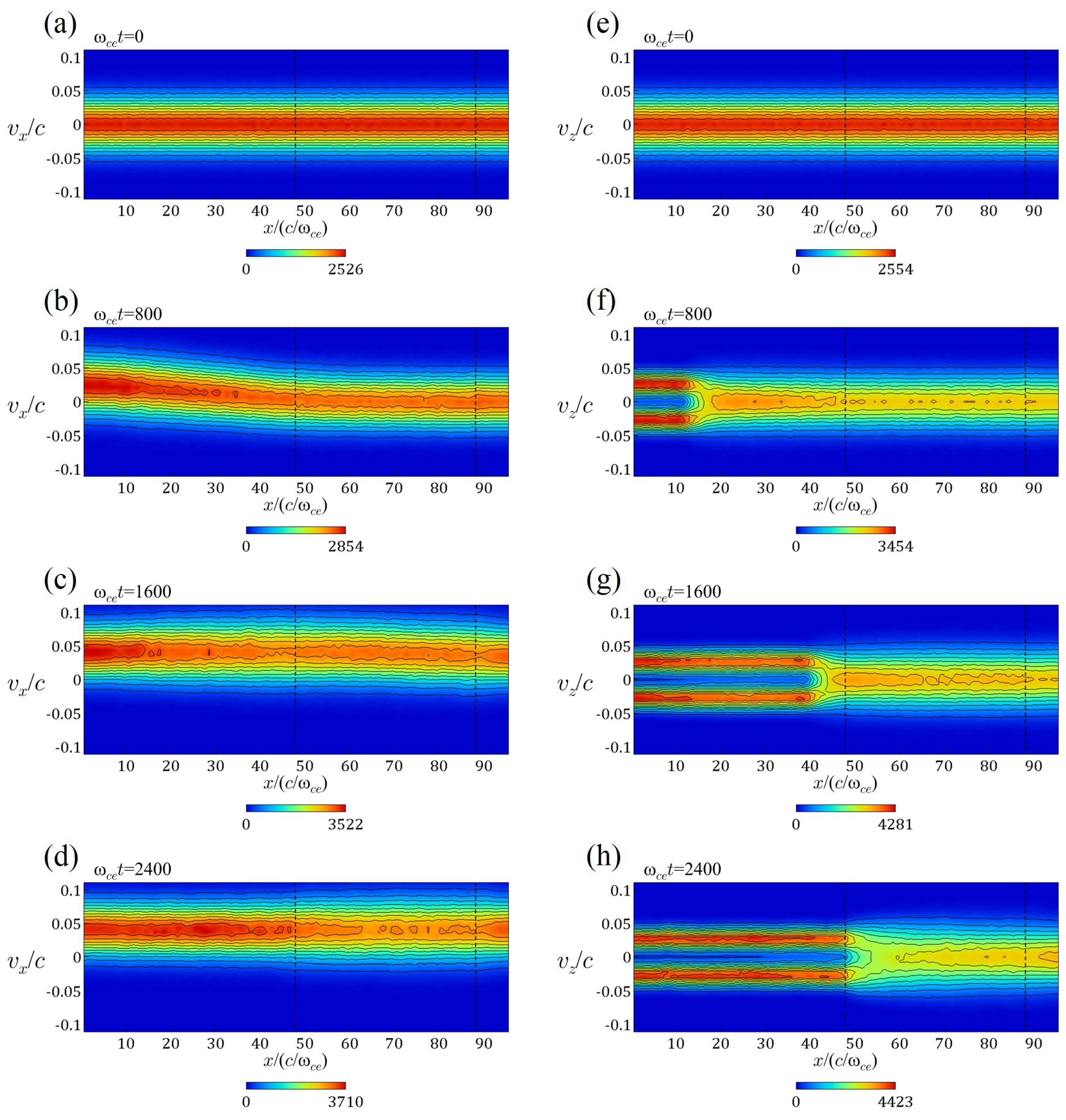
Let us confirm that the Coulomb collision plays the main role in the relaxation of the two streams and the damping of the density variation observed in The Improved Multi-Hierarchy Model 2. Figure 6 shows ion distributions in the phase space of the simulation shown in Figure 5 at various times. Note that only the PIC, collisional PIC, and interface domains are shown. The vertical dotted lines denote the boundary between the PIC and collisional PIC domains () and the boundary between the collisional PIC and interface domains (). Figure 6a–d indicates the distributions in the phase space , where is the velocity parallel to the plasma propagation. Through the simulation, the distributions satisfy the shifted Maxwellian distribution. At the initial time, the averaged velocity is zero in the whole region. We can see that the averaged velocity shifts to positive in the left part of the PIC domain at . At and 2400, the plasma has the same averaged velocity (≃0.04c) in the whole region. In contrast, Figure 6e–h represents the distributions in the phase space , where is the velocity perpendicular to the plasma propagation. Initially, the Maxwellian distribution holds in the whole region. We can find that the two-stream plasma begins to be supplied from the left-side boundary of the PIC domain at . At , the two-peak distribution propagates in the right direction and approaches to the collisional PIC domain. At , the two-peak distribution has entered the collisional PIC domain. We can observe that the two-peak structure of the distribution is relaxed to a one-peak distribution as the plasma propagates in the right direction in the collisional PIC domain. This relaxation is clearly due to the Coulomb collision effect installed in the collisional PIC domain. As a result, a shifted Maxwellian distribution is fully satisfied in , and thus the plasma can smoothly eject to the MHD domain.
3.3. 2D Hierarchy-Interlocking Model
We develop a multi-hierarchy model based on a two-dimensional (two-directional) hierarchy-interlocking [7,22] as shown in Figure 7. This model is named “The Improved Multi-Hierarchy Model 3”. The PIC domain is located in the central area, the interface domain surrounds the PIC domain, and the MHD domain is the outermost area and, further, surrounds the interface domain. Thus, the domain is expressed as follows. The PIC domain: ; the interface domain: ; and the MHD domain: .
Unlike in Section 3.1 and Section 3.2, we use the hand-shake scheme for the upstream direction:
The interconnection function F, however, must be changed to a two-dimensional function. We employ F expressed as
where
Only for the pressure (the thermal velocity), we use
Note that F is used only in the interface domain.
By means of The Improved Multi-Hierarchy Model 3, we perform a plasma flow injection from the MHD domain to the PIC domain to confirm its physical reliability. The simulation box size is , and the number of grid points is . The PIC domain covers the region , the MHD domain is the area , and the interface domain is the narrow region with the width between the PIC and MHD domains.
In this simulation, we adopt non-uniform grids in the x-axis and y-axis [17]. The grid spacing and is a function of the coordinates x and y, respectively. The grid spacing in the PIC and the interface domain is . In the region of , is the smallest (), but in the region of , the grid spacing is larger and reaches at . The same manner is applied to as a function of y. We set that . The uniform magnetic field is taken to be in the z direction. The system is periodic in the z direction and is free in the x and y directions.
As simulation parameters, we set , , , and (). In addition, as the initial condition, the Maxwellian velocity distribution is satisfied in the whole region of the PIC and interface domains, and the plasma density is uniform. The number of ions (electrons) is initially 6,400,000, and increases to ≃1.3 . The number of particles per species per cell is ≃49 initially, and increases to ≃99.
Plasmas are supplied from the outside boundary of the MHD domain. For generating plasma inflows, an external electric field is imposed in the y direction on the line of and is imposed in the x direction on the line of (. The fields and , which are set to be zero, grow first at the center positions on the line and on the line , and the width of the regions where the field is imposed expands to y and x directions, respectively. Eventually, and develop to reach to the constant values on the entire lines of and .
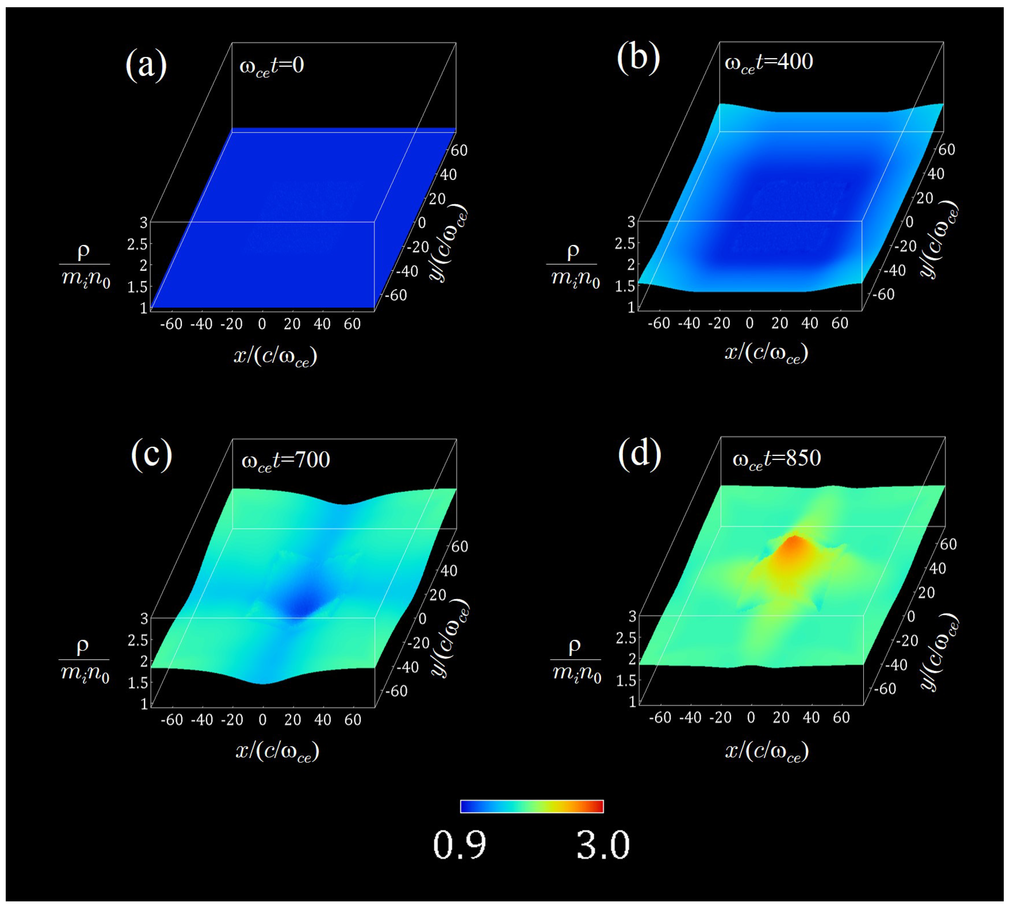
In Figure 8, we demonstrate the spatial profiles of the plasma mass density in plane at: (a) ; (b) 400; (c) 700; and (d) 850, where the mass densities at , 700, and 850 are averaged over 11 snapshots of the mass densities, respectively. As in Figure 3 and Figure 5, the plasma density is normalized to , and both the colors and the height indicate the values of the density. The initial density is uniform () in the whole region. The density in the surrounding MHD domain begins to increase at , and the plasmas are smoothly injected to the central PIC domain through the interface domain at , although small noise is seen in the interface domain. At , the plasma flows have collided at the center of the PIC domain, and then the plasmas are accumulated in the PIC domain. It is confirmed that plasmas are injected smoothly from the MHD domain to the PIC domain by using the two-dimensionally interlocking method.
4. Discussion and Conclusions
We have been developing a multi-hierarchy simulation model for studies on magnetic reconnection. The model is based on the real-space decomposition method, i.e., the real-space in the simulation is divided into multiple domains. In the previous model, the simulation domain consists of the MHD, PIC, and interface domains, and the domains are one-dimensionally interlocked according to the upstream condition. In other words, the main stream of plasmas was from the MHD domain to the PIC domain (but the communication of data is not one-way).
In this work, we have improved our previous multi-hierarchy simulation model and have created three types of new models. Two of the three models mimic the downstream region of magnetic reconnection and one-dimensionally interlock hierarchies. In the first model, two hierarchies are interconnected (the PIC–MHD interlocking) through the interface domain. In the second model, three hierarchies are interconnected (the PIC–collisional PIC–MHD interlocking) through the interface domain. In the collisional PIC domain, the Coulomb collision effect based on a Monte Carlo model is implemented. In the first model, it is found that a plasma satisfying a shifted Maxwellian velocity distribution is smoothly and continuously ejected from the PIC domain to the MHD domain. In the second model, the propagation of a plasma with a non-Maxwellian velocity distribution is simulated. It is observed that the plasma is correctly ejected from the PIC domain to the MHD domain through the collisional PIC domain, in which the non-Maxwellian distribution is relaxed to a shifted Maxwellian distribution owing to the collision effect. The last model couples two hierarchies in the two-directional scheme, in which the upstream condition is used. It is observed that plasmas are smoothly injected from the MHD to the PIC domain. Therefore, we have confirmed the physical reliabilities in the three types of the improved multi-hierarchy models.
Lastly, let us argue that the current improved multi-hierarchy models themselves are not directly applied to realistic systems of magnetic reconnection. For instance, if The Improved Multi-Hierarchy Model 2 is used in the downstream of a collisionless system, important plasma dynamics in the downstream are forcibly reduced by the artificial collision effect. In other words, from the technical viewpoint, the artificial collision effect is shown to be effective for connection from the PIC domain to the MHD domain, but the collision effect must not play a predominant role for collisionless magnetic reconnection. Thereby, for the hierarchy-interlocking in the downstream, further improvement of interlocking methods will be necessary. For example, relaxation algorithms which can interconnect to the MHD domain while maintaining important dynamics will be required.
Author Contributions
Shunsuke Usami developed and improved the multi-hierarchy model based on the interlocking of the PIC code (PASMO code) and the MHD code, and performed simulations by using different types of the multi-hierarchy models. Ritoku Horiuchi and Hiroaki Ohtani mainly developed and optimized the PASMO code. Moreover, Ritoku Horiuchi also contributed to technical ideas for interlocking hierarchies. Mitsue Den contributed to optimization of the MHD code.
Acknowledgments
This simulation work was performed by employing the Plasma Simulator at the National Institute for Fusion Science. This work was partially supported by a Grant-in-Aid for Scientific Research from the Japan Society for the Promotion of Science (Grant Nos. 23340182, 24740374, and 16K17847), the Research Cooperation Program on Hierarchy and Holism in Natural Sciences at the National Institutes of Natural Sciences, and the General Coordinated Research at the National Institute for Fusion Science (NIFS17KNTS049 and NIFS17KNSS085).
Conflicts of Interest
The authors declare no conflict of interest. The founding sponsors had no role in the design of the study; in the collection, analyses, or interpretation of data; in the writing of the manuscript, and in the decision to publish the results.
References
- Yamada, M.; Kulsrud, R.; Ji, H. Magnetic Reconnection. Rev. Mod. Phys. 2010, 82, 603–664. [Google Scholar] [CrossRef]
- Park, H.K.; Lühmann, N.C., Jr.; Donne, J.H.; Glassen, I.G.J.; Domier, C.W.; Mazzucato, E.; Munsat, T.; van de Pol, M.J.; Xia, Z.; TEXTOR Team. Observation of High-Field-Side Crash and Heat Transfer during Sawtooth Oscillation in Magnetically Confined Plasmas. Phys. Rev. Lett. 2006, 96, 195003. [Google Scholar] [CrossRef] [PubMed] [Green Version]
- Øieroset, M.; Lin, R.P.; Phan, T.D.; Larson, D.E.; Bale, S.D. Evidence for Electron Acceleration up to ∼300 keV in the Magnetic Reconnection Diffusion Region of Earth’s Magnetotail. Phys. Rev. Lett. 2002, 89. [Google Scholar] [CrossRef]
- Horiuchi, R.; Den, M.; Tanaka, T.; Ohtani, H.; Usami, S. Macro- and Microphysics of Magnetic Reconnection in a Multi-hierarchy Open System. Plasma Phys. Control. Fusion 2013, 54, 014008. [Google Scholar] [CrossRef]
- Kuznetsova, M.M.; Hesse, M.; Rastätter, L.; Taktakishvili, A.; Toth, G.; De Zeeuw, D.L.; Ridley, A.; Gombosi, T.I. Multiscale Modeling of Magnetospheric Reconnection. J. Geophys. Res. 2007, 112, A10210. [Google Scholar] [CrossRef]
- Sugiyama, M.; Kusano, K. Multi-physics Plasma Simulation by the Interlocking of Two Different Hybrid Models. Astron. Soc. Pacific Conf. Ser. 2008, 385, 228–233. [Google Scholar]
- Makwana, K.D.; Keppens, R.; Lapenta, G. Two-Way Coupling of Magnetohydrodynamic Simulations with Embedded Particle-in-Cell Simulations. Comput. Phys. Commun. 2017, 221, 81–94. [Google Scholar] [CrossRef]
- Usami, S.; Horiuchi, R.; Ohtani, H.; Den, M. Multi-Hierarchy Simulation of Collisionless Driven Reconnection by Real-Space Decomposition. J. Phys. Conf. Ser. 2014, 561. [Google Scholar] [CrossRef]
- Pei, W.; Horiuchi, R.; Sato, T. Long Time Scale Evolution of Collisionless Driven Reconnection in a Two-Dimensional Open System. Phys. Plasmas 2001, 8, 3251–3257. [Google Scholar] [CrossRef]
- Pei, W.; Horiuchi, R.; Sato, T. Ion Dynamics in Steady Collisionless Driven Reconnection. Phys. Rev. Lett. 2001, 87, 235003. [Google Scholar] [CrossRef] [PubMed]
- Ohtani, H.; Horiuchi, R. Open Boundary Condition for Particle Simulation in Magnetic Reconnection Research. Plasma Fusion Res. 2009, 4. [Google Scholar] [CrossRef]
- Usami, S.; Horiuchi, R.; Ohtani, H.; Den, M. Development of Multi-hierarchy Simulation Model for Studies of Magnetic Reconnection. Commun. Comput. Phys. 2008, 4, 537–544. [Google Scholar]
- Ishiguro, S.; Usami, S.; Horiuchi, R.; Ohtani, H.; Maluckov, A.; Škorić, M.M. Multi-Scale Simulation for Plasma Science. J. Phys. Conf. Ser. 2010, 257. [Google Scholar] [CrossRef]
- Usami, S.; Horiuchi, R.; Ohtani, H.; Den, M. Simulation of Plasma Flow Injection with Multi-Hierarchy Model Aiming Magnetic Reconnection Studies. Commun. Comput. Phys. 2012, 11, 1006–1021. [Google Scholar] [CrossRef]
- Usami, S.; Horiuchi, R.; Ohtani, H.; Den, M. First Demonstration of Collisionless Driven Reconnection in a Multi-Hierarchy Simulation. Plasma Fusion Res. 2009, 4. [Google Scholar] [CrossRef]
- Horiuchi, R.; Usami, S.; Ohtani, H.; Moritaka, T. Magnetic Reconnection Controlled by Multi-Hierarchy Physics in an Open System. Plasma Fusion Res. 2010, 5. [Google Scholar] [CrossRef]
- Usami, S.; Horiuchi, R.; Ohtani, H.; Den, M. Development of Multi-Hierarchy Simulation Model with Non-Uniform Space Grids for Collisionless Driven Reconnection. Phys. Plasmas 2013, 20. [Google Scholar] [CrossRef]
- Ogawa, T.; Usami, S.; Horiuchi, R.; Den, M.; Yamashita, K. Development of Simulation Code Connecting Particle-in-Cell and Magnetohydrodynamics on Hierarchical Mesh. JPS Conf. Proc. 2014, 1. [Google Scholar] [CrossRef]
- Ogawa, T.; Usami, S.; Horiuchi, R.; Den, M.; Yamashita, K. Multi-Scale Simulations of Magnetic Reconnection Using Particle-in-Cell and Magnetohydrodynamics with Adaptive Mesh Refinement Technique. Plasma Fusion Res. 2016, 11. [Google Scholar] [CrossRef]
- Sugiyama, T.; Kusano, K. Multi-Scale Plasma Simulation by the Interlocking of Magnetohydrodynamic Model and Particle-in-Cell Kinetic Model. J. Comput. Phys. 2007, 227, 1340–1352. [Google Scholar] [CrossRef]
- Takizuka, T.; Abe, H. A Binary Collision Model for Plasma Simulation with a Particle Code. J. Comput. Phys. 1977, 25, 205–210. [Google Scholar] [CrossRef]
- Daldroff, L.K.S.; Tóth, G.; Gombosi, T.I.; Lapenta, G.; Amaya, J.; Markidis, S.; Brackbill, J.U. Two-Way Coupling of a Global Hall Magnetohydrodynamics Model with a Local Implicit Particle-in-Cell Model. J. Comput. Phys. 2014, 268, 236–254. [Google Scholar] [CrossRef]
Figure 1.
Ideal form of multi-hierarchy simulation for magnetic reconnection.

Figure 2.
Schematic diagram of The Improved Multi-Hierarchy Model 1. The simulation domain consists of the PIC, interface, and MHD domains.
Figure 2.
Schematic diagram of The Improved Multi-Hierarchy Model 1. The simulation domain consists of the PIC, interface, and MHD domains.

Figure 3.
Spatial profiles of the plasma mass density at various times in The Improved Multi-Hierarchy Model 1. A plasma ejects from the PIC domain to the MHD domain via the interface domain.
Figure 3.
Spatial profiles of the plasma mass density at various times in The Improved Multi-Hierarchy Model 1. A plasma ejects from the PIC domain to the MHD domain via the interface domain.


Figure 4.
Schematic diagram of The Improved Multi-Hierarchy Model 2. The simulation domain consists of the PIC, collisional PIC, interface, and MHD domains.
Figure 4.
Schematic diagram of The Improved Multi-Hierarchy Model 2. The simulation domain consists of the PIC, collisional PIC, interface, and MHD domains.

Figure 5.
Spatial profiles of the plasma mass density at various times in The Improved Multi-Hierarchy Model 2. A plasma propagates from the PIC domain to the MHD domain via the collisional PIC and interface domains.
Figure 5.
Spatial profiles of the plasma mass density at various times in The Improved Multi-Hierarchy Model 2. A plasma propagates from the PIC domain to the MHD domain via the collisional PIC and interface domains.


Figure 6.
Ion distributions in the phase space of the simulation shown in Figure 5: (a–d) the distributions in the phase space ; and (e–h) the distributions in the phase space . Note that the PIC domain (), the collisional PIC domain (), and the interface domain () are displayed, and the MHD domain is not displayed.

Figure 7.
Schematic diagram of The Improved Multi-Hierarchy Model 3. The simulation domain is composed of the PIC domain in the central region, the interface domain surrounding the PIC domain, and the MHD domain surrounding the interface domain.
Figure 7.
Schematic diagram of The Improved Multi-Hierarchy Model 3. The simulation domain is composed of the PIC domain in the central region, the interface domain surrounding the PIC domain, and the MHD domain surrounding the interface domain.

Figure 8.
Spatial profiles of the plasma mass density in The Improved Multi-Hierarchy Model 3. Plasmas flow from the surrounding MHD domain to the central PIC domain via the interface domain.
Figure 8.
Spatial profiles of the plasma mass density in The Improved Multi-Hierarchy Model 3. Plasmas flow from the surrounding MHD domain to the central PIC domain via the interface domain.

© 2018 by the authors. Licensee MDPI, Basel, Switzerland. This article is an open access article distributed under the terms and conditions of the Creative Commons Attribution (CC BY) license (http://creativecommons.org/licenses/by/4.0/).
Share and Cite
MDPI and ACS Style
Usami, S.; Horiuchi, R.; Ohtani, H.; Den, M. Improvement of the Multi-Hierarchy Simulation Model Based on the Real-Space Decomposition Method. Plasma 2018, 1, 90-104. https://doi.org/10.3390/plasma1010009
AMA Style
Usami S, Horiuchi R, Ohtani H, Den M. Improvement of the Multi-Hierarchy Simulation Model Based on the Real-Space Decomposition Method. Plasma. 2018; 1(1):90-104. https://doi.org/10.3390/plasma1010009
Chicago/Turabian StyleUsami, Shunsuke, Ritoku Horiuchi, Hiroaki Ohtani, and Mitsue Den. 2018. "Improvement of the Multi-Hierarchy Simulation Model Based on the Real-Space Decomposition Method" Plasma 1, no. 1: 90-104. https://doi.org/10.3390/plasma1010009