The Effect of a Ferromagnetic Steel Enclosure on Magnetic Shielding Systems: Analysis, Modeling, and Experimental Validation

1
College of Civil Engineering and Architecture, Zhejiang University, Hangzhou 310000, China
2
China United Engineering Co., Ltd., Hangzhou 310000, China
3
Hanjia Design Group Co., Ltd., Hangzhou 310000, China
*
Authors to whom correspondence should be addressed.
Machines 2024, 12(5), 317; https://doi.org/10.3390/machines12050317
Submission received: 18 March 2024
/
Revised: 15 April 2024
/
Accepted: 19 April 2024
/
Published: 5 May 2024
(This article belongs to the Section Machine Design and Theory)
Abstract
:The magnetic shielding device, made of high-permeability soft magnetic material, is sensitive to external influences and requires a protective steel enclosure. A steel enclosure, being strongly ferrimagnetic, can alter the surrounding magnetic field distribution, thus impacting the shielding effectiveness. This study proposes a novel analytical approach to quantify this effect, which has not been previously researched. The method develops a simplified finite element simulation model based on the structural symmetry of the steel enclosure. By using this model, this study analyzes the impact of steel structures with varying heights, widths, and remanent magnetization values. The validity of the method is confirmed through experimental tests on steel buildings. The findings offer insights into the optimal placement of magnetic shielding systems and provide theoretical guidance for designing large-scale magnetic shielding devices.
1. Introduction
The faint magnetic field within the magnetic shielding device [1] finds applications in advanced fields such as bio-signaling [2,3], magnetocardiography, and magnetoencephalography [4,5,6], as well as in geophysical research [7,8] and studies of electric dipole moments [9] serving as a vital and widely utilized testing environment for many experiments. Simultaneously, high-precision magnetic measuring instruments, including spin atom gyroscopes and magnetometers [10,11,12], require operation within environments of extremely weak magnetic fields.
Large magnetic shielding devices rely on two key principles for effective magnetic shielding. Firstly, they leverage the magnetic flux shunt effect, as described in references [13,14,15], which involves using high-permeability magnetic materials to redirect magnetic flux away from sensitive areas. Secondly, they take advantage of the eddy current effect, as outlined in references [16,17], where high-conductivity materials are used to dissipate magnetic energy through induced currents, further enhancing the shielding effectiveness. These mechanisms work together to create a highly efficient magnetic shielding system, crucial for maintaining a stable and low-noise magnetic environment for sensitive instruments. However, shielding materials are susceptible to deformation and deterioration, particularly in challenging environmental conditions. Hence, it is essential to use materials like carbon steel to create a protective layer covering the internal magnetic shielding device. When considering factors like stiffness and strength, the selection of carbon steel for the shielding layer typically favors Q355B and similar grades. Q355B [18] is characterized by its ferromagnetic properties, which make it a favored material for protective enclosures. This grade of carbon steel boasts superior mechanical strength and rigidity, making it highly suitable for such applications. Despite its advantages, the notable ferromagnetism of Q355B can alter the distribution of the surrounding magnetic field. This alteration can have a significant impact on the shielding performance of the internal magnetic shielding system. Consequently, it is imperative to conduct a thorough analysis to understand how the spatial positioning of the external steel structure affects the environmental magnetic field.
In steel applications, the remanent magnetic properties of steel structures are widely studied. Several researchers [19,20] have utilized Hall element probes as sensors to detect magnetic changes within steel structures. These probes can identify damaged parts of the steel structure by analyzing the magnetic changes. Steel structures used in construction have different grade requirements, and the magnetic properties of steel materials vary with different grades. Reference [21] conducted magnetic coupling experiments on steel of different grades, analyzed the effect of stress on its magnetic properties, and investigated the variation in magnetic flux at different positions in steel structures. Matsumoto et al. [22] proposed an eddy current magnetic characterization method for evaluating the magnetic properties of materials. This method includes analyzing eddy current signals in the impedance plane when subjecting the material to a low-frequency magnetic field to characterize its magnetic properties. This approach is capable of detecting stress-induced damage in steel materials. The different preparation methods of steel materials also affect their magnetic and other properties. For example, Nichipuruk et al. [23] studied the magnetic properties of 09G2S steel obtained by selective laser melting and casting methods, and analyzed the effects of stress and other factors on its magnetic performance. To analyze the tensile state of steel materials in operational conditions, a set of Helmholtz coils was used to generate a magnetic field and magnetize the steel material in [24]. The magnetic permeability of the steel material varies under different tensile forces. The greatest advantage of this method is that it can determine the tensile state of the steel bars in concrete based on the variation in the measured magnetic permeability. In addition, Amoskov et al. [25] utilized a numerical analysis method based on the filling factor to analyze the magnetic anisotropy of steel reinforcement structures in concrete.
In previous studies, the remanent magnetism of steel structures has been used not only to detect damaged parts but also to analyze and assess the mechanical changes experienced by the structures in their applications. These studies focus on steel as a building material. However, in the field of magnetic shielding, the influence of the internal remanent magnetism of steel structures on the distribution of magnetic fields and magnetic shielding systems has not been extensively researched. To understand the impact of remanent magnetism in steel structures on the performance of magnetic shielding systems, corresponding research is necessary.
This paper proposes an analysis method for the remanence of a steel protective enclosure and analyzes its effect on the shielding performance of a magnetic shielding device. Firstly, this method establishes a mathematical model for the Helmholtz coil and a simplified finite element model based on the circular symmetry of the steel enclosure. By combining these two models, the influence of the steel enclosure’s remanence on the surrounding magnetic field can be analyzed, thus determining its impact on the shielding effectiveness of the magnetic shielding device. To validate the proposed method, the magnetic field around an actual steel structure is measured using instruments such as fluxgate magnetometers. The results demonstrate that the proposed method can accurately analyze the effect of remanence in steel structures. The method proposed in this paper can be utilized to guide the construction of protective enclosures for steel structures outside magnetic shielding devices, minimizing the impact of the steel structures.
2. Modeling and Simulation Methods for Steel Enclosures in Magnetic Shielding Applications
2.1. The Theoretical Analysis of Magnetic Fields in Helmholtz Coils
Large magnetic shielding devices are typically composed of both an active compensation coil and a passive shielding body. The coil, commonly constructed using Helmholtz coils, serves to generate a uniform magnetic field. The shielding body is predominantly constructed using permalloy with high permeability. To enhance the durability of large magnetic shielding devices, a protective enclosure made of carbon steel is commonly employed. The ferromagnetic properties of carbon steel result in a significant alteration in the surrounding magnetic field distribution.
For the quantitative analysis of the impact of remanent magnetization in steel structures on magnetic shielding systems, an active magnetic compensation system composed of Helmholtz coils was selected. Its characteristics, such as magnetic field uniformity, were utilized to observe most importantly the influence of residual magnetization in steel structures.
The Helmholtz coil is composed of two parallel coaxial circular coils. The magnetic field it generates is the sum of the magnetic fields produced by each individual circular coil. A schematic diagram of the magnetic field generated by a circular coil at any point P is shown in Figure 1. In Figure 1, the coil is parallel to the XY plane, with its center on the Z-axis, at a distance L from the origin.
The magnetic induction intensity at any point on the axis of a Helmholtz coil can be calculated as follows [26]:
where is number of turns of a single coil, is the current of the coil, is the distance from any point on the axis to the coordinate circle point, and is the permeability of the vacuum.
The performance of the Helmholtz coil is usually evaluated by the value and the uniformity of the remanence after compensation:
where is the background magnetic field, is the point around the origin, and is the origin magnetic field. For a Helmholtz coil, the uniformity of the magnetic field is a value between 0 and 1. A uniformity value closer to 0 indicates a more uniform magnetic field distribution.
2.2. Simplified Model of a Steel Enclosure
The magnetic shielding device under study includes an external steel protective enclosure. This enclosure has been designed with circumferential symmetry to ensure structural uniformity. This symmetry is harnessed to streamline the finite element model of the steel enclosure, leading to a reduction in computational complexity and an enhancement in precision and efficiency. The simplified model’s cross-sectional representation of the steel enclosure is shown in Figure 2. In the figure, the dashed box outlines the specific region where the distribution of the magnetic field is analyzed. d in the x direction is the distance of the system from the steel structure, and h in the y direction is the height of the system from the ground. Data were gathered at height intervals of Δh from the ground, with each interval set to 5 m. This resulted in lines AB, CD, and EF being located at heights of 0 m, 5 m, and 10 m above the ground, respectively. The arrows along these lines indicate a direction away from the steel structure.
A simplified finite element model of the steel enclosure and Helmholtz coil is shown in Figure 3. The enclosure’s height is denoted by H, and its width by W. The Helmholtz coil serves as a simplified magnetic shielding system, characterized by a radius (R) of 2 m. Both coils are carrying 155.71 A. The distance between the centers of the two coils, O1O2, is 4 m. The distance, d, between the center of the Helmholtz coil and the steel structure is set to 20 m.
In the simulation model, the Earth’s magnetic field is set at 48,498 nT, with 4300 nT in the X-direction, 33,000 nT in the Y-direction, and 35,000 nT in the Z-direction. The finite element model is divided into 446,232 free tetrahedral meshes. The residual magnetic field characteristics of the steel structure are defined using “Magnetic Field (MF)—Ampere’s Law—Magnetization Model—Residual Magnetic Flux Density”. The Helmholtz coil is defined using “Magnetic Field (MF)—Edge Current”.
2.3. Simulation Analysis
In construction, the optimal choice for steel structures is Q355B due to its high strength, good corrosion resistance, low susceptibility to wear, and ease of installation and processing. In the field of magnetic shielding, Q355B is also commonly used for the steel structures outside magnetic shielding devices. However, the residual magnetism characteristics of Q355B can influence the distribution of the surrounding magnetic field, thereby affecting the magnetic shielding system. Therefore, simulation analysis and discussion were conducted using the simplified finite element model in Section 2.2.
Firstly, the residual magnetism of carbon steel structures is not fixed. It is necessary to study the effects of steel structures with different levels of remanence magnitude. Here, the steel structure is set to be 30 m high and 25 m wide, which are typical dimensions for an actual steel structure. The remanence of the steel structure is set to be 2 × 10⁷, 5 × 10⁷, and 8 × 10⁷ nT, respectively. The magnetic field values at distances of 0 m, 5 m, and 10 m from the ground are simulated and shown in Figure 4. From the figure, it can be seen that the larger the remanence inside the steel structure, the greater its impact on the magnetic field, and the larger the affected area. This conclusion holds true at different heights above the ground.
Furthermore, the dimensions (height and width) of the steel protective enclosure can change according to practical engineering needs. Next, the height and width of the steel protective enclosure are adjusted to analyze the effect of different sizes of steel structures on the magnetic field distribution. The results are shown in Figure 5. In the figure, the height of the steel structure is divided into 20 m, 30 m, and 40 m, while the width is divided into 10 m, 25 m, and 40 m. The remanence of the steel structure in Figure 5 is set to 5 × 10⁷ nT.
In Figure 5a,c,e, where the width of the steel structures is 25 m and the height varies from 20 m to 30 m, the magnetic field distribution curves in the figure move upward with a relatively small magnitude. When the height increases from 30 m to 40 m, the magnetic field distribution curves move upward with a larger magnitude. In summary, with the remanence of the steel structure being constant, increasing the height of the steel structure results in a larger internal magnetic field. In Figure 5a, at a height of 15 m above the ground, the magnetic field distribution curve rises again after decreasing to the ambient magnetic field. This is because the lower height of the steel structure leads to a greater impact of the remanence of the top of the steel structure.
In Figure 5b–d, where the height of the steel structures is 30 m and the width varies from 10 m to 40 m, the magnetic field distribution curves in the figure move upward, but with a smaller magnitude. When the remanence of the steel structure is constant and the height of the steel structure is fixed at 30 m, the influence of the top of the steel structure is relatively small, and this influence does not change significantly as the width of the steel structure increases. Therefore, it can be concluded that the width of the steel structure has a smaller impact on the magnetic field distribution compared to the height. Consequently, the test points reaching the ambient remanence in Figure 5b–d are all around 20 m.
Inside the steel enclosure with a height of 30 m, a width of 25 m, and a remanent magnetization of 5 × 10⁷ nT, a magnetic shielding system represented by Helmholtz coils was added. This allows for the analysis of the effect of the steel structure’s remanent magnetization value on the magnetic shielding system. The center of the Helmholtz coils is positioned 20 m laterally from the steel structure and 2 m above the ground. Simulation results along the centerline of the Helmholtz coil are presented in Figure 6. In Figure 6, the horizontal axis represents the distance between the centerline O1O2 of the Helmholtz coils, where point O1 is at 0 m and point O2 is at 4 m. Therefore, the center point is located at coordinate 2 m. The uniformity of the Helmholtz coils at any point can be obtained from Equation (3). Here, the magnetic field uniformity at point O1 is selected for analysis and discussion. Without the steel structure, the magnetic field at the center point is 35,265 nT, and at point O1, it is 33,015 nT, resulting in a field uniformity of 0.0638. With the presence of the steel structure, the magnetic field at the center is 33,868 nT, and at point O1, it is 40,895 nT, resulting in a field uniformity of 0.20747. This indicates that under the influence of the steel structure, the uniformity of the Helmholtz coil’s magnetic field deteriorates. The significant difference in uniformity demonstrates that the inherent residual magnetism of the steel structure has a considerable impact on the gradient distribution of the magnetic field.
3. Test Method and Discussion of Test Results
3.1. Principle and Method of Measurement
To analyze the impact of large steel structures, we used a three-axis fluxgate sensor, Mag-03, to measure the actual magnetic field in the interior space of the steel structures. The Mag-03 sensor has a low noise level of less than 6 pT/Hz1/2, a wide bandwidth of 3000 Hz, and a range of 100,000 nT. To facilitate height adjustment during the measurement process, a non-magnetic bracket was used.
The magnetometer bias is eliminated by performing a 180° reversal in each direction during the measurement. The actual magnetic field data can be calculated as half of the difference between the two sets of data before and after inversion, which is expressed by the following formula:
where is the first measured value, is the measured value of the 180° reverse, and is the true value. The total magnetic field B is as follows:
where is the east–west magnetic field (facing the west is positive), is the magnetic field perpendicular to the ground (facing the ground is positive), and is the north–south magnetic field (facing the north is positive).
This study focused on a building constructed with Q355B material, featuring circumferential symmetry. This building was simplified for analysis, as shown in Figure 3, with a height (H) of 30 m and a width (W) of 25 m. The measurement procedure was conducted within the magnetic field area illustrated in Figure 2. Data collection involved measuring at intervals of Δh at different heights above the ground, with Δh set at 5 m. Specifically, points were selected along lines AB, CD, and EF, which are 0 m, 5 m, and 10 m above the ground, respectively, with the arrow direction indicating movement away from the steel structure. Measurements were taken at each height, ranging from 10 m to 45 m away from the steel structure, at 5 m intervals. The ranging instrument is used to measure the distance between the steel structure and the test point.
3.2. Analysis of Measurement Results
In this section, the magnetic field distribution of an actual steel structure device was tested. When the remanence of the steel structure was set to 5 × 10⁷ nT, the test values and simulation values of the magnetic field distribution are shown in Figure 7. It is evident from the figure that the test values on line AB on the ground closely match the simulation data, with a relatively large error of about 4.6% occurring after the magnetic field decreases to the ambient magnetic field. Based on the analysis results of this experiment, after obtaining the magnetic field distribution around the steel structure through testing, the changes in the internal remanence of the steel structure can be determined through simulation, thereby analyzing the relevant performance of the steel structure.
Further tests were conducted on the magnetic field distribution at heights of 5 m and 10 m, as shown in Figure 8. It can be observed from the figure that the magnetic field gradually decreases when moving away from the steel structure. At a distance of 20 m from the steel structure, the tested magnetic field value is consistent with the ambient magnetic field. This is consistent with the simulation results of Figure 5c.
4. Conclusions
This paper presents a finite element analysis method to analyze and study the influence of a steel protective enclosure on the surrounding magnetic field distribution, further investigating its impact on magnetic shielding systems. The method establishes a simplified finite element simulation model of a circularly symmetric steel protective enclosure and uses it to analyze the effects of enclosures with different sizes and remanent magnetization values on the surrounding magnetic field distribution. Additionally, the method quantitatively analyzes the negative impact of the presence of steel structures on the magnetic field uniformity of Helmholtz coils. The method has been tested on an actual steel structure protective enclosure, obtaining the real magnetic field distribution under the influence of steel structures. The actual test results are consistent with the simulation analysis results. The results show that when the remanent magnetism of the steel structure is certain, the farther away from the steel protective enclosure it is, and the smaller the influence of the inherent magnetism of the steel on the magnetic field. When the height of the steel structure is less than 30 m, the width is less than 40 m, and the ferromagnetism is less than 5 × 10⁷nT, the magnetic shielding system will not be affected at a distance of more than 20 m away from the steel structure. This method provides important guidance for the construction of steel structure protective enclosures and large-scale ultra-high-performance magnetic shielding devices.
Author Contributions
Conceptualization, Y.C., J.H., Y.L. and F.L.; methodology, Y.C., J.H., Y.L. and F.L.; validation, Y.C., J.H., Y.L. and F.L.; formal analysis, Y.C., J.H. and F.L.; investigation, Y.C. and Y.L.; resources, J.H., Y.L. and F.L.; data curation, Y.C., J.H., Y.L. and F.L.; writing—original draft preparation, Y.C., J.H., Y.L. and F.L.; writing—review and editing, J.H., Y.L. and F.L.; visualization, J.H., Y.C. and F.L.; supervision, J.H. and F.L.; project administration, Y.C., J.H., Y.L. and F.L. All authors have read and agreed to the published version of the manuscript.
Funding
This research received no external funding.
Institutional Review Board Statement
Not applicable.
Informed Consent Statement
Not applicable.
Data Availability Statement
The original contributions presented in the study are included in the article, further inquiries can be directed to the corresponding authors.
Conflicts of Interest
Author Feng Lu is employed by the company China United Engineering Co. Ltd. Author Jiang Huang is employed by the company Hanjia Design Group Co., Ltd. The remaining authors declare that the research was conducted in the absence of any commercial or financial relationships that could be construed as a potential conflict of interest.
References
- Holmes, N.; Rea, M.; Chalmers, J.; Leggett, J.; Edwards, L.J.; Nell, P.; Pink, S.; Patel, P.; Wood, J.; Murby, N.; et al. A lightweight magnetically shielded room with active shielding. Sci. Rep. 2022, 12, 13561. [Google Scholar] [CrossRef] [PubMed]
- Zhu, K.; Kiourti, A. A Review of Magnetic Field Emissions from the Human Body: Sources, Sensors, and Uses. IEEE Open J. Antennas Propag. 2022, 3, 732–744. [Google Scholar] [CrossRef]
- Roth, B.J. Biomagnetism: The First Sixty Years. Sensors 2023, 23, 4218. [Google Scholar] [CrossRef] [PubMed]
- Holmes, N.; Leggett, J.; Boto, E.; Roberts, G.; Hill, R.M.; Tierney, T.M.; Shah, V.; Barnes, G.R.; Brookes, M.J.; Bowtell, R. A Bi-Planar Coil System for Nulling Background Magnetic Fields in Scalp Mounted Magnetoencephalography. Neuroimage 2018, 181, 760–774. [Google Scholar] [CrossRef] [PubMed]
- Yang, J.; Zhang, X.; Han, B.; Wang, J.; Wang, L. Design of Biplanar Coils for Degrading Residual Field in Magnetic Shielding Room. IEEE Trans. Instrum. Meas. 2021, 70, 6010110. [Google Scholar] [CrossRef]
- Yang, K.; Wu, D.; Gao, W.; Ni, T.; Zhang, Q.; Zhang, H.; Huang, D. Calibration of SQUID Magnetometers in Multichannel MCG System Based on Bi-Planar Coil. IEEE Trans. Instrum. Meas. 2022, 71, 1002209. [Google Scholar] [CrossRef]
- Afach, S.; Bison, G.; Bodek, K.; Burri, F.; Chowdhuri, Z.; Daum, M.; Fertl, M.; Franke, B.; Grujic, Z.; Helaine, V.; et al. Dynamic Stabilization of the Magnetic Field Surrounding the Neutron Electric Dipole Moment Spectrometer at the Paul Scherrer Institute. J. Appl. Phys. 2014, 116, 084510. [Google Scholar] [CrossRef]
- Chupp, T.E.; Fierlinger, P.; Ramsey-Musolf, M.J.; Singh, J.T. Electric dipole moments of atoms, molecules, nuclei, and particles. Rev. Mod. Phys. 2019, 91, 015001. [Google Scholar] [CrossRef]
- Kuchler, F.; Babcock, E.; Burghoff, M.; Chupp, T.; Degenkolb, S.; Fan, I.; Fierlinger, P.; Gong, F.; Kraegeloh, E.; Kilian, W.; et al. A New Search for the Atomic EDM of 129Xe at FRM-II. Hyperfine Interact. 2016, 237, 95. [Google Scholar] [CrossRef]
- Tashiro, K.; Wakiwaka, H.; Matsumura, K.; Okano, K. Desktop Magnetic Shielding System for the Calibration of High-Sensitivity Magnetometers. IEEE Trans. Magn. 2011, 47, 4270–4273. [Google Scholar] [CrossRef]
- Long, T.; Han, B.; Song, X.; Suo, Y.; Jia, L. Fast In-Situ Triaxial Remanent Magnetic Field Measurement for Single-Beam SERF Atomic Magnetometer Based on Trisection Algorithm. Photonic Sens. 2023, 13, 230311. [Google Scholar] [CrossRef]
- Fan, W.F.; Quan, W.; Liu, F.; Pang, H.Y.; Xing, L.; Liu, G. Performance of Low-Noise Ferrite Shield in a K-Rb-Ne-21 Co-Magnetometer. IEEE Sens. J. 2020, 20, 2543–2549. [Google Scholar] [CrossRef]
- Kajiwara, G.; Harakawa, K.; Ogata, H.; Kado, H. High-performance magnetically shielded room. IEEE Trans. Magn. 1996, 32, 2582–2585. [Google Scholar] [CrossRef]
- Ayres, N.J.; Ban, G.; Bison, G.; Bodek, K.; Bondar, V.; Bouillaud, T.; Clement, B.; Chanel, E.; Chiu, P.-J.; Crawford, C.B.; et al. The very large n2EDM magnetically shielded room with an exceptional performance for fundamental physics measurements. Rev. Sci. Instrum. 2022, 93, 095105. [Google Scholar] [CrossRef] [PubMed]
- Packer, M.; Hobson, P.J.; Davis, A.; Holmes, N.; Leggett, J.; Glover, P.; Hardwicke, N.L.; Brookes, M.J.; Bowtell, R.; Fromhold, T.M. Magnetic Field Design in a Cylindrical High-Permeability Shield: The Combination of Simple Building Blocks and a Genetic Algorithm. J. Appl. Phys. 2022, 131, 093902. [Google Scholar] [CrossRef]
- Allmendinger, F.; Brauneis, B.; Schmidt, U. Degaussing procedure and performance enhancement by low-frequency shaking of a 3-layer magnetically shielded room. Rev. Sci. Instrum. 2023, 94, 115105. [Google Scholar] [CrossRef] [PubMed]
- Xu, Z.; Zhang, Z.; Wu, B.; Wang, H.; Kong, X.; Wang, M. A Study of Enclosed Magnetic Shielding Room by Simulation. IEEE Trans. Appl. Supercond. 2021, 31, 2500404. [Google Scholar] [CrossRef]
- Ren, Z.; Qin, X.; Zhang, Q.; Sun, Y. Damage Evolution Characterization of Low Carbon Alloy Steel Based on Multiaxial Fatigue Test and DIC. In Proceedings of the IEEE International Conference on Prognostics and Health Management (ICPHM), Montreal, QC, Canada, 5–7 June 2023; pp. 239–245. [Google Scholar] [CrossRef]
- Chen, D.F.; Zhang, J.T.; Xiao, H.Y. Design of an instrument of magnetic measurement for steel structures. In Proceedings of the 12th IEEE International Conference on Electronic Measurement and Instruments (ICEMI), Qingdao, China, 16–18 July 2015; pp. 718–721. [Google Scholar]
- Kim, J.-W.; Park, S. Magnetic Flux Leakage Sensing and Artificial Neural Network Pattern Recognition Based Automated Damage Detection and Quantification for Wire Rope Non-Destructive Evaluation. Sensors 2018, 18, 109. [Google Scholar] [CrossRef] [PubMed]
- Weng, G.Y.; Wang, J.T.; Liu, Y.; Zhu, X.Y.; Dai, J.B. Magnetic Stress Sensing System for Nondestructive Stress Testing of Structural Steel and Steel Truss Components Based on Existing Magnetism. Sensors 2020, 20, 4043. [Google Scholar] [CrossRef]
- Matsumoto, T.; Uchimoto, T.; Takagi, T.; Dobmann, G.; Ducharne, B.; Oozono, S.; Yuya, H. Investigation of electromagnetic nondestructive evaluation of residual strain in low carbon steels using the eddy current magnetic signature (EC-MS) method. J. Magn. Magn. Mater. 2019, 479, 212–221. [Google Scholar] [CrossRef]
- Nichipuruk, A.P.; Stashkov, A.N.; Shchapova, E.A.; Kazantseva, N.V.; Makarova, M.V. Structure and Magnetic Properties of 09G2S Steel Obtained by the Selective Laser Melting Method. Phys. Solid State 2022, 64, 148–153. [Google Scholar] [CrossRef]
- Ferrandez, D.; Moron, C.; Saiz, P.; Moron, A. Magnetic variation in construction steels under tensile stress. Empirical research with Helmholtz coils. Mater. Constr. 2021, 71, e243. [Google Scholar] [CrossRef]
- Amoskov, V.; Bazarov, A.; Belyakov, V.; Gapionok, E.; Gribov, Y.; Kaparkova, M.; Kukhtin, V.; Lamzin, E.; Lyublin, B.; Ovsyannikov, D.; et al. Calculation of magnetic field from steel rebar of building with machine producing high stray field. Fusion Eng. Des. 2018, 135, 165–173. [Google Scholar] [CrossRef]
- Pang, H.Y.; Duan, L.H.; Quan, W.; Wang, J.; Wu, W.F.; Fan, W.F.; Liu, F. Design of Highly Uniform Three-Dimensional Spherical Magnetic Field Coils for Atomic Sensors. IEEE Sens. J. 2020, 20, 11229–11236. [Google Scholar] [CrossRef]
Figure 1.
A schematic diagram of the magnetic field generated by a current-carrying circular conductor at an arbitrary point.
Figure 1.
A schematic diagram of the magnetic field generated by a current-carrying circular conductor at an arbitrary point.
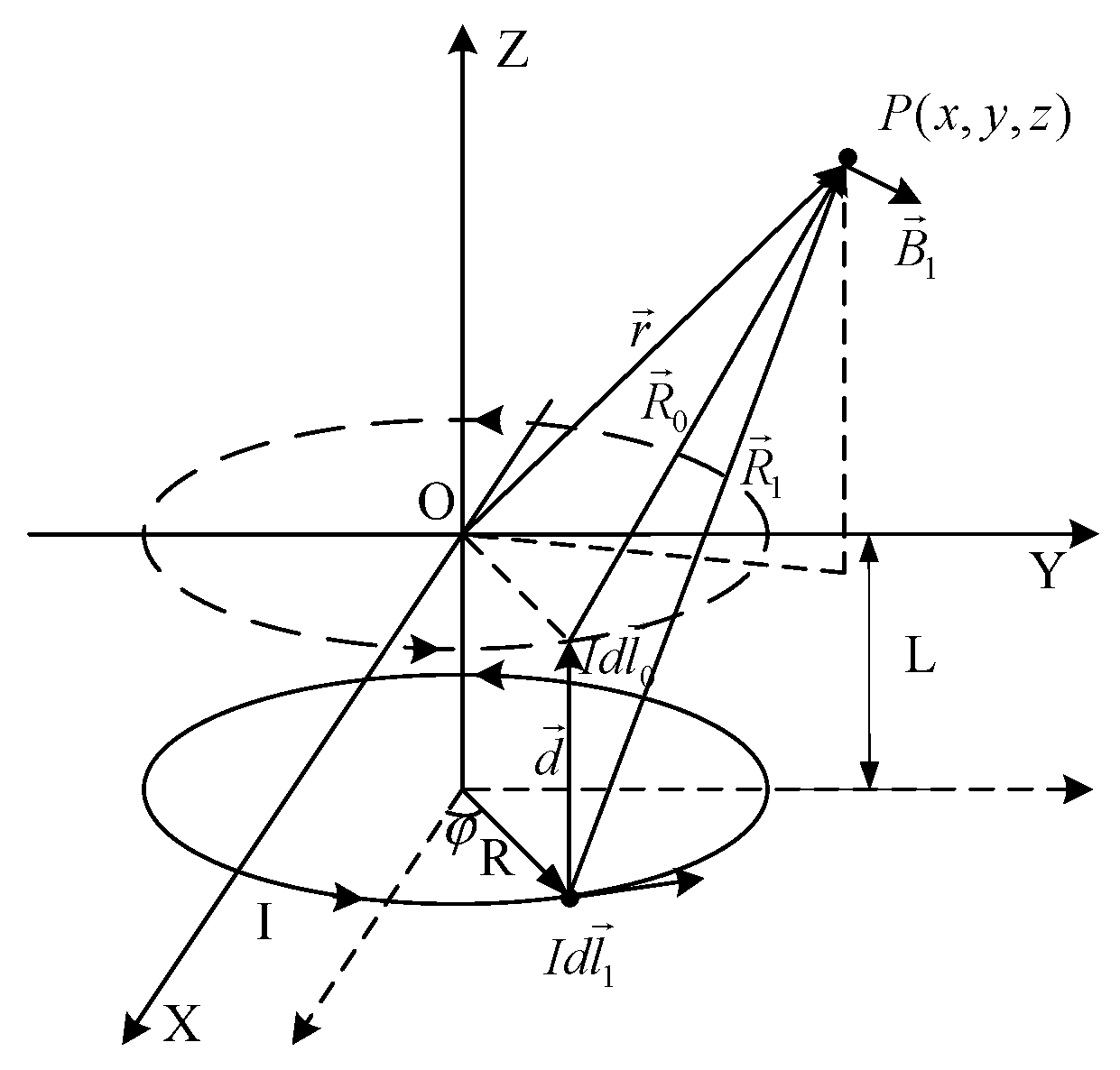
Figure 2.
The cross-sectional view of the simplified model of the steel enclosure.

Figure 3.
The finite element simulation model of the steel structure and Helmholtz coils.

Figure 4.
The effect of steel structures with different ferromagnetism on the environmental magnetic field distribution. (a) The magnetic field values at a distance of 0 m from the ground, (b) the magnetic field values at a distance of 5 m from the ground, and (c) the magnetic field values at a distance of 10 m from the ground.

Figure 5.
The influence of different sizes of steel structures on the magnetic field distribution.

Figure 6.
The magnetic field distribution on the axis of the Helmholtz coil.

Figure 7.
The measurement results are compared with the simulation results.

Figure 8.
Measurement result curve of magnetic field.

Disclaimer/Publisher’s Note: The statements, opinions and data contained in all publications are solely those of the individual author(s) and contributor(s) and not of MDPI and/or the editor(s). MDPI and/or the editor(s) disclaim responsibility for any injury to people or property resulting from any ideas, methods, instructions or products referred to in the content. |
© 2024 by the authors. Licensee MDPI, Basel, Switzerland. This article is an open access article distributed under the terms and conditions of the Creative Commons Attribution (CC BY) license (https://creativecommons.org/licenses/by/4.0/).
Share and Cite
MDPI and ACS Style
Cheng, Y.; Huang, J.; Luo, Y.; Lu, F. The Effect of a Ferromagnetic Steel Enclosure on Magnetic Shielding Systems: Analysis, Modeling, and Experimental Validation. Machines 2024, 12, 317. https://doi.org/10.3390/machines12050317
AMA Style
Cheng Y, Huang J, Luo Y, Lu F. The Effect of a Ferromagnetic Steel Enclosure on Magnetic Shielding Systems: Analysis, Modeling, and Experimental Validation. Machines. 2024; 12(5):317. https://doi.org/10.3390/machines12050317
Chicago/Turabian StyleCheng, Yuan, Jiang Huang, Yaozhi Luo, and Feng Lu. 2024. "The Effect of a Ferromagnetic Steel Enclosure on Magnetic Shielding Systems: Analysis, Modeling, and Experimental Validation" Machines 12, no. 5: 317. https://doi.org/10.3390/machines12050317
Note that from the first issue of 2016, this journal uses article numbers instead of page numbers. See further details here.