
Improving the Corrosion Resistance of Micro-Arc Oxidization Film on AZ91D Mg Alloy through Silanization

Key Laboratory of Superlight Materials and Surface Technology, Ministry of Education, Harbin Engineering University, Harbin 150001, China
*
Authors to whom correspondence should be addressed.
Metals 2024, 14(5), 569; https://doi.org/10.3390/met14050569
Submission received: 10 April 2024
/
Revised: 5 May 2024
/
Accepted: 7 May 2024
/
Published: 12 May 2024
(This article belongs to the Special Issue Preparation and Processing Technology of Advanced Magnesium Alloys)
Abstract
:The presence of inherent micro-pores and micro-cracks in the micro-arc oxidation (MAO) film of Mg alloys is a key factor contributing to substrate corrosion. A composite film layer with high corrosion resistance was achieved through silanizing the micro-arc oxidation film. The corrosion performance of the MAO films treated with various silane coupling agents was assessed through morphological characterization and electrochemical tests. SEM graphs depicted that the silane film can effectively seal the defects existing in micro-arc oxidation film, and electrochemical tests indicated the significant corrosion resistance improvement of MAO film after silanization treatment.
1. Introduction
Magnesium alloys are extensively employed in the aerospace sector, primarily for structural components, fuel tanks, and interior equipment of spacecraft, aiming to enhance performance and facilitate lightweight design [1,2]. Micro-arc oxidation (MAO) technology refers to the production of an oxidized film on metal surfaces through discharge plasma electrolysis treatment, which can significantly enhance the corrosion resistance and wear resistance of magnesium alloys [3]. Owing to its exceptional impact on surface modification and enhancement of metal material properties, MAO technology has found extensive applications in aerospace industries to protect the Mg alloy [4,5]. Nonetheless, the micro-arc oxide film may have some challenges, as the roughness and porosity of its surface could impact its corrosion and wear resistance in certain cases [6,7]. Thus, further surface modification of MAO films remains a key area of focus in current research [8].
Currently, to address the defects in MAO film, two primary methods have been developed to improve the integrity of the film: the one-step and two-step methods. The one-step method involves adding nanoparticles to the electrolyte during the formation of MAO film to increase its density and fill any micro-pores [9,10]. The two-step method involves building a composite film layer on the formed MAO film to repair any existing defects on the film surface through the external film layer [11]. The two-step method for micro-arc oxidizing is typically conducted through hydrothermal treatment [12,13], electroless plating [7,14], layered double hydroxide (LDH) [15], or other post-treatment. Although the external membrane layer of the composite film constructed through the two-step method is usually less abrasion-resistant and susceptible to mechanical damage compared to the traditional one-step method, it can provide better sealing and corrosion resistance, even after breakage [16,17]. Silanization treatment is a green surface treatment technology with high chemical resistance and thermal stability, which can effectively protect the surface of the substrate from environmental erosion and is among the methods employed. The formation of the silane film occurs through the dehydration of hydroxyl groups in M-OH on the metal surface and the reaction with silanol molecules or oligomers, resulting in the formation of M-O-Si bonds [18,19]. Additionally, the three-dimensional (3D) network structure formed by cross-linked -Si-O-Si- bonds provides high resistance to corrosion [20,21]. A. Mandelli et al. [22] demonstrated the effectiveness of both Osi (Trimethyl (1-methylethenyloxy) silane) and BTSE (1,2-bis(trimethylsilyl)ethane) silane coupling agents in sealing the micro-pores of the MAO film layer and repairing any microscopic defects present in the AM60B MAO film.
This study organized a comparative investigation into the corrosion resistance of silane films on MAO surfaces and the improved corrosion resistance mechanism of MAO-silane composite film by utilizing various silane coupling agents as precursors. Several characterization tools, such as scanning electron microscopy (SEM), energy dispersive X-ray spectroscopy (EDS), and Fourier-transform infrared spectroscopy (FTIR), were utilized to analyze the morphology and composition of the MAO film surface. In addition, long-term EIS spectra are employed to analyze the prolonged corrosion behavior of composite coatings, thus discerning the failure modes of these composite coatings. Through analysis and discussion of the experimental results, the corrosion mechanism of the MAO-silane composite film was revealed, providing valuable guidance for practical engineering applications.
2. Materials and Methods
2.1. Preparation of MAO Film and Sealing Treatment
The chemical composition of the AZ91D magnesium alloy used in this study was analyzed using inductively coupled plasma atomic emission spectrometry (ICP-AES3600A, Nanjing, China). The analysis revealed the following composition (wt.%): Al 9.03, Zn 0.73, Mn 0.21, Si 0.002, Fe 0.001, Cu 0.001, Ni 0.003, with Mg as the balance element. The specimen, with dimensions of 40 mm × 35 mm × 5 mm, underwent gradual grinding to a 2000 # grit size. Subsequently, it was cleaned with deionized water and anhydrous ethanol and dried with cold air.
MAO treatment was performed on AZ91D magnesium alloy using a Doercoat II (Beijing, China) plasma electrolytic oxidation power supply, which includes an oxidation power supply, electrolyzer, electrode system, stirring system, and cooling system. An alkaline silicate system (5 g/L Na2SiO3, 4 g/L KO, and 4 g/L KF) was selected as the electrolyte, and the pulse oxidation current mode (with a current density of 8 A/dm2, duty factor +50/−30, frequency 600 Hz) was used. The MAO film was formed by using the magnesium alloy workpiece as the anode and the graphite plate as the cathode, with the temperature controlled at 35 °C. The specimens with the MAO film were cleaned with deionized water and anhydrous ethanol, and then dried with cold air.
Three types of silane coupling agents—KH560 (γ-Glycidoxypropyltrimethoxysilane, contains an amino functional group and three ethoxy groups), BTSE (contains two silane groups and four sulfur atoms), and DTMS (dodecyltrimethoxysilane, contains two methyl groups and two ethoxy groups)—were chosen to prepare the silane composite film. The composite film was formed through a film-forming process (immersing the sample in silane hydrolysate at 50 °C for 20 min) and a curing process (at 120 °C in an oven for 1 h). The silane hydrolysate was prepared by mixing the silane coupling agent with ethanol and deionized water at a volumetric ratio of 1:1:4. The pH was adjusted to 4.0 with acetic acid, and the mixture was hydrolyzed for 8 h at 40 °C.
2.2. Electrochemical Tests
Electrochemical tests and neutral salt spray experiments were conducted to assess the corrosion resistance of the MAO and MAO-silane films. The electrochemical tests were performed in a 3.5 wt.% NaCl solution using the Zahner 6eX (Kronach, German) electrochemical workstation and a conventional three-electrode system. The saturated calomel electrode (SCE) served as the reference electrode, a platinum sheet as the counter electrode, and the exposed 1 cm2 specimen as the working electrode. Potentiodynamic polarization tests were used to evaluate the corrosion resistance of the films. The potentiodynamic polarization tests were conducted in 3.5 wt.% NaCl solution within a potential range of −0.3 V vs. OCP to 1.6 V at a scan rate of 333 µV/s, with the tests being stopped when the anodic current reached 1 mA/cm2. Electrochemical impedance spectroscopy (EIS) measurements were performed with a sinusoidal signal ranging from 10−2 to 105 Hz and an amplitude of 10 mV. The experimental data were analyzed using Zahner Analysis software. Prior to the tests, the system was allowed to stand for 10 min to stabilize the surface condition of the sample.
2.3. Salt Spray, Contact Angle Test, and Surface Characterization
The neutral salt spray tests were conducted in accordance with ASTM-B117 [23] using a salt spray tester (VSC/KWT1000, Ballingen, German) with a 5 wt.% NaCl solution. The specimen was coated with a molten mixture of paraffin and rosin to mitigate edge effects. The Barrington II contact angle tester was employed to assess the in situ conversion film of the magnesium alloy after silanization.
MAO films, the surface morphology after silanization, and the corresponding surface elemental distribution were analyzed using scanning transmission electron microscopy (FEI Titan Themis 200 TEM) and energy dispersive spectroscopy (Bruker Super-X EDS system, Billerica, MA, USA). Fourier transform infrared spectroscopy (FTIR) using a Nicolet 6700 instrument (Green Bay, WI, USA) was utilized to analyze the surface composition of the MAO-silane composite layer. As the sample of the composite membrane layer is solid, it was necessary to scrape off the membrane layer with a lancet, grind with a mortar, and mix it evenly with potassium bromide powder for pressing. The spectral range was set at 400 cm−1 to 4000 cm−1 with a resolution of 2 cm−1, and the testing was repeated three times for each sample to ensure result accuracy.
3. Results
3.1. Contact Angle of MAO-Silanization Composite Film
The surface hydrophobicity results of the MAO film on AZ91D magnesium alloy after silanization treatment with KH560, BTSE, and DTMS are depicted in Figure 1. The contact angles (θ) of the MAO film treated with KH560, BTSE, and DTMS were 63.9°, 33.7°, and 115.6°, respectively. The high surface energy of the MAO film leads to rapid spreading of water droplets on its surface, rendering it challenging to measure the contact angle of the untreated film. Silanization of the MAO film can significantly lower its surface energy, enhance its hydrophobicity, and decrease the chances of contact between the corrosive medium and the film, thereby enhancing its corrosion resistance.
The choice of silane coupling agent significantly impacts the surface hydrophobicity of MAO-silane composite films. One end of the three silanes is Si-O-H, which binds to the hydroxyl group on the surface of the MAO film or other oligomers, forming a relatively dense silane film. The other end of the hydrolyzed product of BTSE is Si-O-H, while KH560 features an epoxide functional group that shares a similar polar bond with the O-H bond in a water molecule [8,24]. Consequently, the surface contact angle of BTSE and KH560 silane films is less than 90°. The hydrolyzed product of DTMS contains a hydrophobic long chain (dodecyl), leading to the formation of a predominantly hydrophobic silane film. As depicted in Figure 1, the surface hydrophobicity of the MAO film treated with the three silanes ranks in the order of DTMS > KH560 > BTSE.
3.2. Micro-Morphology
Figure 2 illustrates the surface morphology of the MAO film post-silanization with KH560, BTSE, and DTMS. Noticeable micro-pores and cracks were visible on the surface of the MAO film. Following silanization, some micro-cracks and small micro-pores on the MAO film surface were sealed, although the treatment had minimal impact on larger micro-pores. This could be attributed to the inability of the silane solution to penetrate the interior of the micro-pores, thus preventing the formation of a silane film within them. Consequently, the incomplete coverage of the silane film on the MAO film surface hinders the fundamental enhancement of the corrosion resistance of the MAO-silane composite film. Moreover, the acidic silane pre-hydrolysate may react with the exposed magnesium alloy through the defects in the MAO film, leading to the generation of corrosion products that impede the formation of a silane film within the micro-pores, compromising the membrane’s integrity [25]. Nonetheless, the corrosion resistance of the silane film is not clearly discernible from Figure 2.
3.3. Electrochemical Measurements
Figure 3 depicts the potentiodynamic polarization curves of the MAO film both before and after silanization treatment with KH560, BTSE, and DTMS. Following the sealing treatment, a remarkable decrease in the corrosion current density of the MAO film and a positive shift in the corrosion potential were observed, indicating that all the silane coupling agents significantly contributed to the closure of structural defects in the MAO film, thereby enhancing its corrosion resistance. Furthermore, the MAO film treated with BTSE and DTMS exhibited a partial increase in the pitting potential of the film layer, which may be attributed to variations in the densification of the silane film. Additionally, the corrosion current density of MAO, MAO-KH560, MAO-BTSE, and MAO-DTMS film were 1.38× 10⁻⁷, 7.68 × 10⁻⁹, 7.86 × 10⁻⁸, and 1.05 × 10⁻⁸ A/cm2, respectively, which demonstrated lower corrosion current density of the MAO-KH560 and MAO-DTMS composite films.
The hydrolysis products of BTSE contain six Si-O-Hs, resulting in a relatively denser silane film compared to KH560 and DTMS. However, the highly hydrophilic surface of the BTSE silane film makes it more vulnerable to infiltration by corrosive media, which can penetrate the micro-defects of the MAO-silane composite film and reduce its long-term corrosion resistance. The slight repulsive effect of the hydrophobic long chains in DTMS on the hydroxyl groups results in the outer layer of the silane film being hydrophobic, leading to a more effective barrier against corrosive media.
Figure 4 illustrates the electrochemical impedance spectra of the AZ91D magnesium alloy MAO film before and after silanization with different silane coupling agents. The figure shows that the impedance modulus value, phase angle, and capacitance arc radius all increased after silanization, indicating that the silanization treatment can effectively enhance the integrity of the MAO film and improve its corrosion resistance. Therefore, the corrosion resistance of the MAO film is improved as a result. The results of the EIS test also laterally confirmed the results of the potentiodynamic polarization curves.
3.4. Long-Term Immersion Experiments
As depicted in Figure 5, the corrosion resistance of the MAO film decreased with increasing immersion time. At 0.5 h immersion time, the impedance comprises a high-frequency capacitance arc, a medium-frequency capacitance arc, a low-frequency capacitance arc, and a low-frequency inductive reactance arc [26]. Initially, the corrosive medium reacts with the magnesium substrate at the film/substrate interface, and the impedance modulus decreases rapidly. With increasing immersion time, the impedance modulus continues to decrease. The process can be analyzed by data fitting using the equivalent circuit shown in Figure 6a, in which Rs represents solution resistance, and R1 and R2 represent the resistance of the loose and dense layers of the MAO film, respectively. CPE1 indicates the interaction between the outermost MAO film and the corrosive medium. The decrease in the peak phase angle predicts that the loose layer in the MAO film is infiltrated by the corrosive medium, leading to an increase in the conductivity of the MAO layer and a decrease in the resistance of the film layer. As the immersion time extended, the loose layer gradually failed. Similarly, CPE2 provides information on the dense MAO layer, and with increasing immersion time, this layer also gradually failed. CPEdl indicates the corrosion occurring at the oxide film/substrate interface. The micro-defects on the surface of the MAO film provide channels for corrosive media to reach the MAO film/substrate interface. The low-frequency inductive reactance arc (L) indicates the occurrence of localized pitting corrosion on the AZ91D magnesium alloy substrate [27], and Rt means the charge transfer resistance.
Figure 7 shows the EIS of MAO film treated with silane KH560, BTSE, and DTMS, respectively. In Figure 7a–c, an inductive reactance arc was not observed in the Nyquist spectra at an immersion time of 0.5 h, indicating that the corrosive medium did not reach the MAO/matrix interface. This proves that the silane treatment acts as a physical shielding effect on the corrosive medium, significantly improving the corrosion resistance of the MAO film. As the immersion process proceeded, a similar inductive reactance arc to that in Figure 5 appeared. When the immersion time reached 198 h, the loose layer of the MAO-silane film composite had been dissolved by the corrosive medium. Therefore, Figure 6b is used for fitting before 0.5 h, and Figure 6a is utilized when an inductive reactance arc appears [28].
The low-frequency impedance modulus values (|Z|0.01Hz) can be used to evaluate the protective coating failure process [28]. Figure 8 shows |Z|0.01Hz before and after the silanization treatment of the MAO film. The modulus satisfies MAO-DTMS > MAO-KH560 > MAO-BTSE > MAO film, which is consistent with the results of polarization tests. During the immersion process, the corrosive medium passes through the silane film and reacts with the magnesium alloy substrate, resulting in a gradual decrease in |Z|0.01Hz of the composite layer. Additionally, during the early stage (stage I) of immersion (0.5–8 h), the |Z|0.01Hz of the MAO-silane composite layer decreased rapidly from 106–107 Ω·cm2 to 104–105 Ω·cm2. From 8–96 h of immersion (stage II), the decrease in the |Z|0.01Hz slowed down with prolonged immersion time due to the gradual accumulation of corrosion products in the micro-pores. This accumulation hindered the mass transfer process of the corrosive medium, thus delaying the corrosion reaction. The |Z|0.01Hz was further reduced in stage III, which may be the reason for the gradual complete failure of the silane film.
The fitting results of R1 and R2 with immersion time are shown in Figure 9. The trend of R1 and R2 with immersion time is similar. During the initial stage of immersion (0.5 h), the R1 and R2 values for the MAO-silane film are 1–2 orders of magnitude higher than those for the MAO film, indicating a significant enhancement in the physical shielding capability of the MAO film due to silanization treatment. In the middle phase of immersion (8–48 h), R1 and R2 gradually decrease with immersion time, as the silane film hinders the mass transfer process of the corrosive medium. As the immersion time reaches 48–72 h, the resistance values of R1 and R2 decrease significantly once more, likely because the silane film is hydrolyzed by the corrosive medium, leading to a reduction in the density of the silane film.
A higher resistance value of the charge transfer resistance (Rt) indicates greater difficulty in charge transfer at the interface between the magnesium alloy substrate and the corrosive medium [29]. In Figure 10, during the initial stage of immersion (0.5 h), the Rt value for MAO-DTMS was 108 Ω·cm2, while the Rt values for MAO-KH560 and MAO-BTSE composite layers ranged from 105 to 106 Ω·cm2, significantly higher than that of the MAO film. From 0.5 to 8 h, Rt decreased rapidly, indicating the initial degradation of the silane film layer. As the immersion time progresses, the decrease in Rt may be attributed to the accumulation of corrosion products at the interface, leading to the hindrance of charge transfer. However, as the immersion time further extends, the corrosion channel widens, facilitating charge transfer.
The EIS analysis showed that silanization treatment effectively enhances the corrosion resistance of the MAO film, but the protective effect of the silane film diminishes gradually with prolonged immersion time.
3.5. Long-Term Salt Spray Experiments
Figure 11 illustrates the macroscopic morphology of the MAO specimen surface under neutral salt spray conditions before and after silanization treatment. The red circles in Figure 11 represent the locations at which the visible corrosion features are first observed, caused by the accumulation of corrosion products on the surface of the MAO film or small pits, which gradually change into large areas of corrosion products in the course of time. The untreated MAO film exhibited its initial corrosion point in the neutral salt spray environment at 24 h. As the salt spray duration increased, both the number of corrosion points and the corrosion area expanded. By 96 h, the MAO-KH560 and MAO-BTSE composite films displayed their first corrosion point, with the number of corrosion points and corrosion area remaining consistent with the duration of the salt spray exposure. The MAO film treated with DTMS silanization did not exhibit corrosion in the salt spray environment until 552 h, demonstrating superior resistance to salt-spray-induced corrosion.
Figure 12 illustrates the micro-surface morphology of the MAO-silane composite film after the neutral salt spray test. Following the salt spray test, the micro-arc oxidation film underwent significant changes in surface morphology, resulting in the formation of a layer of loose and porous flaky corrosion products on the original surface. The surface of the MAO-DTMS composite film layer did not exhibit noticeable changes, possibly due to the effective surface hydrophobicity of the DTMS silane film, which inhibited the occurrence of corrosion reaction. Volcano-like protrusions of corrosion products were observed on the surface of the MAO-KH560 and MAO-BTSE composite film layers, indicating that the surface of the KH560 or BTSE silane membranes was incomplete, leading to the occurrence of corrosion.
4. Discussion
Figure 2 displays the surface of the AZ91D magnesium alloy MAO film, revealing distinct structural defects such as micro-holes and micro-cracks. In the micro-arc oxidation process, the application of high voltage causes breakdown in the thinnest region of the oxide film, leading to the ejection of high-temperature molten oxide along the discharge channel under the influence of the electric and pressure fields. Quenching occurs when the molten oxide encounters the electrolyte, resulting in the formation of a “crater”-like microscopic morphology and generating stresses that lead to the formation of micro-cracks.
Figure 13 depicts the cross-sectional morphology and elemental surface distribution of the MAO film before and after the silanization treatment. In Figure 13a, the MAO film is divided into an outer porous layer and an inner dense layer. The outer layer is thicker and more porous, whereas the inner layer is thinner but denser, exhibiting fewer defects. Furthermore, the elemental distribution diagram of the MAO film cross-section indicates that the film is predominantly composed of Mg, O, and Si. In Figure 13b, a “Si”-rich film layer is observed on the surface of the MAO film, indicating that the silanization treatment can effectively create a protective silane film on the MAO film. Moreover, significant enrichment at the micro-cracks was observed, indicating that silane can be deposited within the micro-cracks of the MAO film, enhancing the integrity of the MAO membrane [30].
Figure 14 displays the FT-IR spectra of the magnesium alloy MAO film before and after the silanization treatment with DTMS. The peak at 3653 cm−1 in the MAO film corresponds to the metal hydroxide O-H stretching vibration peak [31], while the peak at 1008 cm−1 indicates the presence of Mg2SiO4 in the MAO film [32]. Following silanization, peaks were observed at 2932 cm−1, 2858 cm−1, 1101 cm−1, and 903 cm−1, corresponding to the antisymmetric CH2, symmetric CH2, Si-O-S, and Si-OH stretching vibrations in the silane film [33], respectively. Notably, the peaks at 3653 cm−1 and 1008 cm−1 persist after the silanization of the MAO film, possibly indicating the destruction of the MAO film during sample preparation or the incomplete sealing of the MAO film by the silanization process.
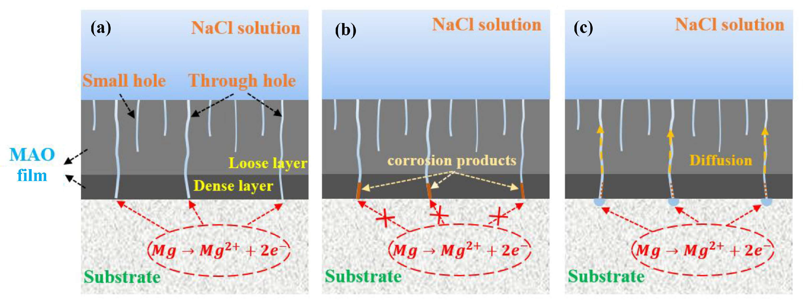
The corrosion mechanism of the MAO-silane composite film in a 3.5 wt.% NaCl solution is illustrated in Figure 15 based on the preceding analysis. This mechanism can be categorized into three stages based on Figure 7. In Stage I, the corrosive medium is obstructed by the silane film covering the MAO surface, providing effective corrosion resistance. Despite some corrosive medium penetrating the film through defects, the corrosion rate remains relatively low, as depicted in Figure 15a. As the immersion time increases, corrosion at the interface between the magnesium alloy substrate and the MAO intensifies, preventing timely outward diffusion of corrosion products. This results in the gradual accumulation of corrosion products in the pores, consequently decelerating the corrosion rate, as shown in Figure 15b. In Stage III, the surface silane film undergoes gradual hydrolysis and dissolution, allowing corrosion products to diffuse outward through the exposed defects. This re-exposes the magnesium alloy substrate at the defects to the corrosive medium, accelerating the corrosion process, as illustrated in Figure 15c.
5. Conclusions
The silanization treatment serves as a pivotal method in effectively sealing minute defects within the magnesium alloy MAO film, the hydrolysis product of the silane coupling agent plays a crucial role in determining the hydrophilicity and density of the resultant silane film. The degree of crosslinking in the silane film can enhance its sealing effect on defects within the MAO film, while hydrophobicity can resist the intrusion of corrosive media at minor defect sites, thereby substantially augmenting its long-term corrosion resistance. Consequently, the choice of silane coupling agent profoundly impacts the defect-sealing efficacy of the MAO film and the corrosion resistance of the composite layer. Particularly noteworthy, KH560 and DTMS silanization treatments manifest a notably enhanced improvement in the corrosion resistance of the MAO film. This enhancement is evidenced by a nearly two orders of magnitude reduction in the corrosion current density, accompanied by a significant increase in the value of |Z|0.01Hz.
Author Contributions
Conceptualization, J.L. and H.Y.; methodology, Y.W.; software, Y.S.; validation, Z.X., Y.S. and Y.W.; formal analysis, J.L. and H.Y.; investigation, Y.W.; resources, Y.S. and Y.W.; data curation, Z.X.; writing—original draft preparation, J.L. and H.Y.; writing—review and editing, Z.X.; visualization, Z.X.; supervision, Y.W.; project administration, Y.S. and Y.W.; funding acquisition, Y.W. All authors have read and agreed to the published version of the manuscript.
Funding
This research was funded by National Natural Science Foundation of China (grant numbers: 51971073, 52001155); Postdoctoral funding project of Heilongjiang Province (grant number: LBH-Z23122), and the Natural Science Foundation of Jiangxi Province (grant number: 20212BAB214038).
Data Availability Statement
The raw data supporting the conclusions of this article will be made available by the authors on request.
Conflicts of Interest
The authors declare no conflicts of interest.
References
- Tang, X.; Zhang, Q.; Mei, D.; Liu, M.; Wang, L.; Zhu, S.; Guan, S. The uniform corrosion of biodegradable Mg alloy induced by protein addition in Hanks’ balanced salt solution. Colloids Surf. A 2024, 690, 133824. [Google Scholar] [CrossRef]
- Song, Y.; Dai, J.; Sun, S. A comparative study on the corrosion behavior of AZ80 and EW75 Mg alloys in industrial atmospheric environment. Mater. Today Commun. 2024, 38, 108263. [Google Scholar] [CrossRef]
- Wu, M.; Jiang, F. Preparation, interface properties and corrosion behavior of nano-modified MAO ceramic film on 5B70 Al alloy. J. Alloys Compd. 2023, 967, 171829. [Google Scholar] [CrossRef]
- He, R.Y.; Wang, B.Y.; Xiang, J.H.; Pan, T.J. Effect of copper additive on microstructure and anti-corrosion performance of black MAO films grown on AZ91 alloy and coloration mechanism. J. Alloys Compd. 2021, 889, 161501. [Google Scholar] [CrossRef]
- Gong, Y.; Geng, J.; Huang, J.; Chen, Z.; Wang, M.; Chen, D.; Wang, H. Self-healing performance and corrosion resistance of novel CeO2-sealed MAO film on aluminum alloy. Surf. Coat. Tech. 2021, 417, 127208. [Google Scholar] [CrossRef]
- Lee, H.-B.; Sheu, H.-H.; Jian, J.-S.; Hsiao, R.-C. Study on the Characteristics of MAO/Polymer/Ni Three-Layer Composite Film formed on AZ31 Magnesium Alloy. Int. J. Electrochem. Sci. 2021, 16, 211246. [Google Scholar] [CrossRef]
- Lee, C.-Y.; Lee, J.-L.; Jian, S.-Y.; Chen, C.-A.; Aktug, S.L.; Ger, M.-D. The effect of fluoride on the formation of an electroless Ni–P plating film on MAO-coated AZ31B magnesium alloy. J. Mater. Res. Technol. 2022, 19, 542–556. [Google Scholar] [CrossRef]
- Zhu, J.; Jia, H.; Liao, K.; Li, X. Improvement on corrosion resistance of micro-arc oxidized AZ91D magnesium alloy by a pore-sealing coating. J. Alloys Compd. 2021, 889, 161460. [Google Scholar] [CrossRef]
- Wang, S.-Y.; Si, N.-C.; Xia, Y.-P.; Li, L. Influence of nano-SiC on microstructure and property of MAO coating formed on AZ91D magnesium alloy. Trans. Nonferrous Met. Soc. China 2015, 25, 1926–1934. [Google Scholar] [CrossRef]
- Cui, L.; Wang, Y.; Hu, L.; Gao, L.; Du, B.; Wei, Q. Mechanism of Pb (II) and methylene blue adsorption onto magnetic carbonate hydroxyapatite/graphene oxide. RSC Adv. 2015, 5, 9759–9770. [Google Scholar] [CrossRef]
- Liu, R.; Xu, D.; Liu, Y.; Wu, L.; Yong, Q.; Xie, Z.-H. Enhanced corrosion protection for MAO coating on magnesium alloy by the synergism of LDH doping with deposition of 8HQ inhibitor film. Ceram. Int. 2023, 49, 30039–30048. [Google Scholar] [CrossRef]
- Zhang, Y.; Luo, S.; Wang, Q.; Ramachandran, C.S. Effect of hydrothermal treatment on the surface characteristics and bioactivity of HAP based MAO coating on Ti-6Al-4V alloy. Surf. Coat. Tech. 2023, 464, 129566. [Google Scholar] [CrossRef]
- Ma, F.C.; Liu, P.; Chen, Y.; Li, W.; Liu, X.K.; Chen, X.H.; He, D.H. Various Morphologies Hydroxyapatite Crystals on Ti MAO Film Prepared by Hydrothermal Treatment. Phys. Procedia 2013, 50, 442–448. [Google Scholar] [CrossRef]
- Chen, C.-A.; Jian, S.-Y.; Lu, C.-H.; Lee, C.-Y.; Aktuğ, S.L.; Ger, M.-D. Evaluation of microstructural effects on corrosion behavior of AZ31B magnesium alloy with a MAO coating and electroless Ni-P plating. J. Mater. Res. Technol. 2020, 9, 13902–13913. [Google Scholar] [CrossRef]
- Li, W.; Tian, A.; Li, T.; Zhao, Y.; Chen, M. Ag/ZIF-8/Mg-Al LDH composite coating on MAO pretreated Mg alloy as a multi-ion-release platform to improve corrosion resistance, osteogenic activity, and photothermal antibacterial properties. Surf. Coat. Tech. 2023, 464, 129555. [Google Scholar] [CrossRef]
- Yang, W.; Gao, Y.; Xu, D.; Zhao, J.; Ke, P.; Wang, A. Bactericidal abilities and in vitro properties of diamond-like carbon films deposited onto MAO-treated titanium. Mater. Lett. 2019, 244, 155–158. [Google Scholar] [CrossRef]
- Chen, Q.; Zhu, X.; Jiang, Y.; Yang, L.; Liu, H.H.; Song, Z. Development and characterization of MAO/PLA-nHA nanocomposite coatings on pure zinc for orthopedic applications. Surf. Coat. Tech. 2024, 478, 130452. [Google Scholar] [CrossRef]
- Cao, H.; Fang, M.; Jia, W.; Liu, X.; Xu, Q. Remarkable improvement of corrosion resistance of silane composite coating with Ti3C2Tx MXene on copper. Compos. Part B 2022, 228, 109427. [Google Scholar] [CrossRef]
- Huang, J.; Dun, Y.; Wan, Q.; Wu, Z.; Zhao, X.; Tang, Y.; Zhang, X.; Zuo, Y. Improved corrosion resistance of MAO coating on Mg-Li alloy by RGO modified silanization. J. Alloys Compd. 2022, 929, 167283. [Google Scholar] [CrossRef]
- Han, J.; Liu, E.; Zhou, Y.; Zhao, S.; Yan, H.; Hu, C.; Kang, J.; Han, Q.; Su, Y. Robust superhydrophobic film on aluminum alloy prepared with TiO2/SiO2-silane composite film for efficient self-cleaning, anti-corrosion and anti-icing. Mater. Today Commun. 2023, 34, 105085. [Google Scholar] [CrossRef]
- Chen, X.; Li, G.; Lian, J.; Jiang, Q. Study of the formation and growth of tannic acid based conversion coating on AZ91D magnesium alloy. Surf. Coat. Tech. 2009, 204, 736–747. [Google Scholar] [CrossRef]
- Mandelli, A.; Bestetti, M.; Da Forno, A.; Lecis, N.; Trasatti, S.; Trueba, M. A composite coating for corrosion protection of AM60B magnesium alloy. Surf. Coat. Tech. 2011, 205, 4459–4465. [Google Scholar] [CrossRef]
- ASTM-B117; Standard Practice for Operating Salt Spray (Fog) Apparatus. ASTM Standard: West Conshohocken, PA, USA, 2019.
- Shi, C.; Zhang, L.; Zhao, J.; Tian, L.; Wang, S.; Liu, X.; Liu, G.; Shao, Y. Characterization and performance of organic-inorganic composite zinc phosphate with nano-sheet structure synthesized by a composite reaction of sol-gel with silane modification. Surf. Interfaces 2024, 47, 104225. [Google Scholar] [CrossRef]
- Wang, G.; Guo, L.; Ruan, Y.; Zhao, G.; Zhang, X.; Liu, Y.; Kim, D.-E. Improved wear and corrosion resistance of alumina alloy by MAO and PECVD. Surf. Coat. Tech. 2024, 479, 130556. [Google Scholar] [CrossRef]
- Yang, C.; Wang, C.; Zhao, X.; Shen, Z.; Wen, M.; Zhao, C.; Sheng, L.; Wang, Y.; Xu, D.; Zheng, Y.; et al. Superhydrophobic surface on MAO-processed AZ31B alloy with zinc phosphate nanoflower arrays for excellent corrosion resistance in salt and acidic environments. Mater. Des. 2024, 239, 112769. [Google Scholar] [CrossRef]
- Pinto, R.; Carmezim, M.J.; Ferreira, M.G.S.; Montemor, M.F. A two-step surface treatment, combining anodisation and silanisation, for improved corrosion protection of the Mg alloy WE54. Prog. Org. Coat. 2010, 69, 143–149. [Google Scholar] [CrossRef]
- Yang, Z.; Che, J.; Zhang, Z.; Yu, L.; Hu, M.; Sun, W.; Gao, W.; Fan, J.; Wang, L.; Liu, G. High-efficiency graphene/epoxy composite coatings with outstanding thermal conductive and anti-corrosion performance. Compos. Part A 2024, 181, 108152. [Google Scholar] [CrossRef]
- Wang, S.; Ma, X.; Bai, J.; Niu, J.; Ma, R.; Du, A.; Zhao, X.; Fan, Y.; Li, G. Study on the structure and corrosion behavior of hot-dipped Zn–6Al–3Mg alloy coating in chlorine-containing environment. Corros. Sci. 2024, 231, 112001. [Google Scholar] [CrossRef]
- Wang, Y.Q.; Deng, Y.Z.; Shao, Y.W.; Wang, F.H. New sealing treatment of microarc oxidation coating. Surf. Eng. 2014, 30, 31–35. [Google Scholar] [CrossRef]
- Yang, H.; Li, S.; Liang, Z. Anodized oxidative electrosynthesis of magnesium silicate whiskers. Int. J. Electrochem. Sci. 2013, 8, 9332–9337. [Google Scholar] [CrossRef]
- Meng, G.; Dou, B.; Zhang, T.; Liu, B.; Wang, F. Growth Behaviors of Layered Double Hydroxide on Microarc Oxidation Film and Anti-Corrosion Performances of the Composite Film. J. Electrochem. Soc. 2016, 163, C917. [Google Scholar]
- Zanotto, F.; Grassi, V.; Frignani, A.; Zucchi, F. Protection of the AZ31 magnesium alloy with cerium modified silane coatings. Mater. Chem. Phys. 2011, 129, 1–8. [Google Scholar] [CrossRef]
Figure 1.
Contact angle of MAO film treated with (a) KH560, (b) BTSE, and (c) DTMS.

Figure 2.
Surface morphology of MAO film modified by different silane coupling agents: (a) MAO; (b) MAO-KH560; (c) MAO-BTSE; (d) MAO-DTMS.
Figure 2.
Surface morphology of MAO film modified by different silane coupling agents: (a) MAO; (b) MAO-KH560; (c) MAO-BTSE; (d) MAO-DTMS.

Figure 3.
Potentiodynamic polarization curves of MAO film before and after treatment with different silane coupling agents.
Figure 3.
Potentiodynamic polarization curves of MAO film before and after treatment with different silane coupling agents.

Figure 4.
(a) Bode and (b) Nyquist diagrams of MAO film before and after silanization with different silane coupling agents.
Figure 4.
(a) Bode and (b) Nyquist diagrams of MAO film before and after silanization with different silane coupling agents.

Figure 5.
(a) Bode and (b) Nyquist diagrams for MAO film in 3.5 wt.% NaCl solution.
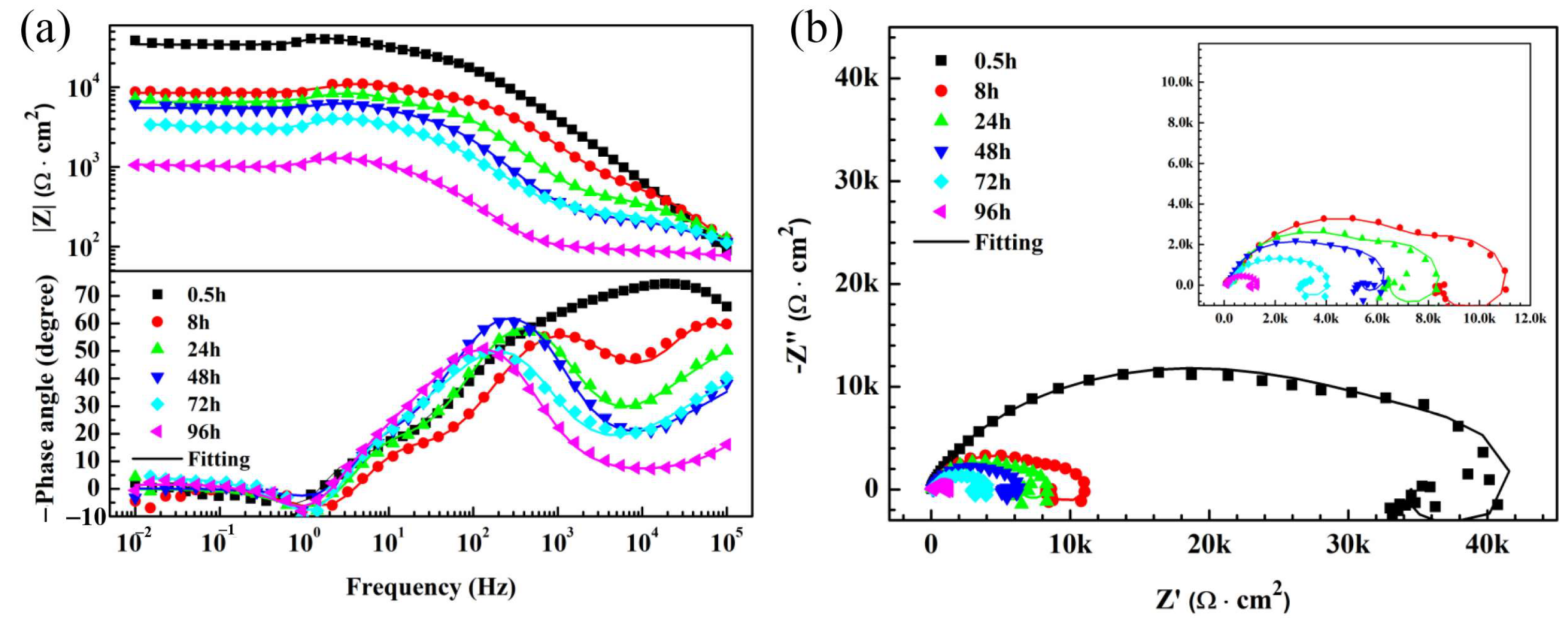
Figure 6.
Two types of electrical equivalent circuit used for fitting the EIS spectra. (a) corrosion stage, (b) initial stage.
Figure 6.
Two types of electrical equivalent circuit used for fitting the EIS spectra. (a) corrosion stage, (b) initial stage.

Figure 7.
(1) Bode and (2) Nyquist diagram of AZ91D Mg alloy MAO film immersing in 3.5 wt.% NaCl solution for different time after silanization with different silane coupling agents: (a) KH560; (b) BTSE; (c) DTMS.
Figure 7.
(1) Bode and (2) Nyquist diagram of AZ91D Mg alloy MAO film immersing in 3.5 wt.% NaCl solution for different time after silanization with different silane coupling agents: (a) KH560; (b) BTSE; (c) DTMS.

Figure 8.
Time dependence of impedance modulus at 0.01 Hz.

Figure 9.
Time dependence of (a) R1 and (b) R2 of MAO film before and after silanization.
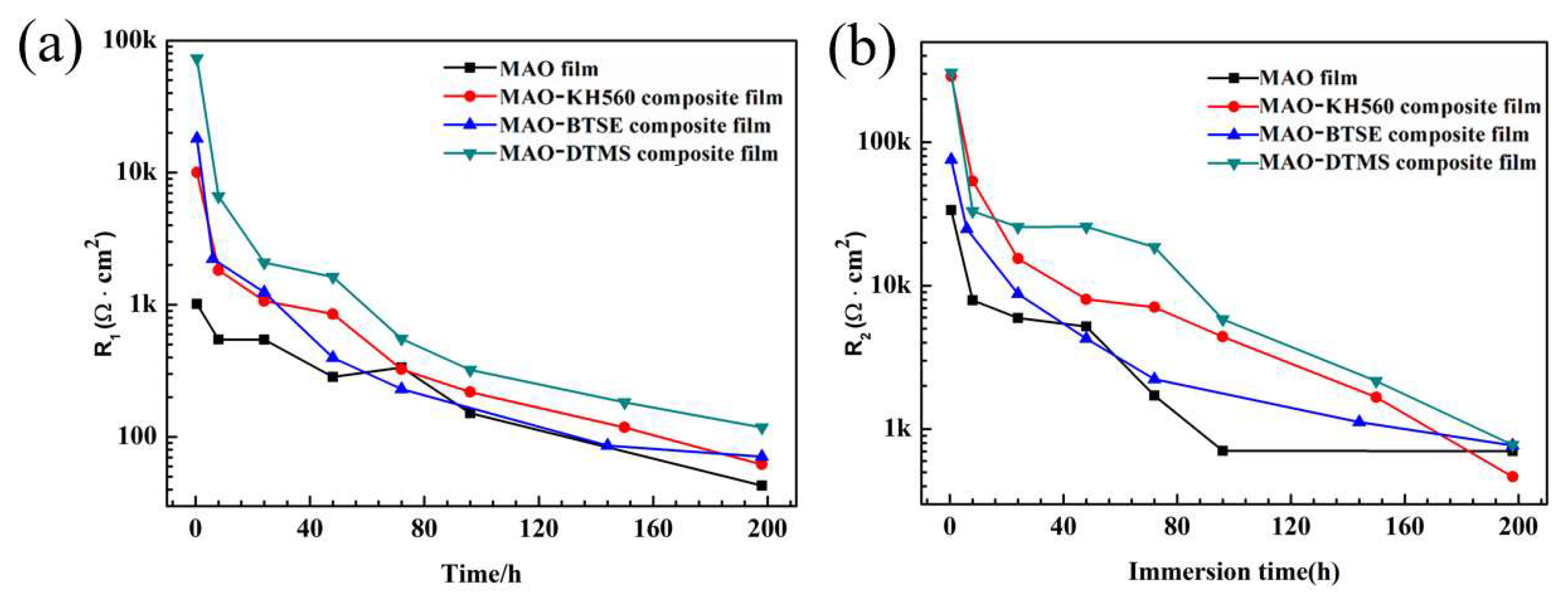
Figure 10.
Time dependence of Rt of MAO film before and after silanization.

Figure 11.
The macroscopic morphology of MAO film tested by neutral salt spray at different time before and after treatment with different silane coupling agents.
Figure 11.
The macroscopic morphology of MAO film tested by neutral salt spray at different time before and after treatment with different silane coupling agents.

Figure 12.
The microscopic surface morphology of MAO film after salt spray test before and after treatment with different silane coupling agents: (a) MAO coating; (b) KH560; (c) BTSE; (d) DTMS.
Figure 12.
The microscopic surface morphology of MAO film after salt spray test before and after treatment with different silane coupling agents: (a) MAO coating; (b) KH560; (c) BTSE; (d) DTMS.

Figure 13.
Micromorphology of the cross-section of MAO film (a) before and (b) after DTMS silanization.
Figure 13.
Micromorphology of the cross-section of MAO film (a) before and (b) after DTMS silanization.

Figure 14.
FTIR spectra of MAO film before and after DTMS silanization.

Figure 15.
Schematic diagram of corrosion process of MAO-silane composite film. (a) initial stage, (b) corrosion product accumulation, (c) diffusion stage.
Figure 15.
Schematic diagram of corrosion process of MAO-silane composite film. (a) initial stage, (b) corrosion product accumulation, (c) diffusion stage.
Disclaimer/Publisher’s Note: The statements, opinions and data contained in all publications are solely those of the individual author(s) and contributor(s) and not of MDPI and/or the editor(s). MDPI and/or the editor(s) disclaim responsibility for any injury to people or property resulting from any ideas, methods, instructions or products referred to in the content. |
© 2024 by the authors. Licensee MDPI, Basel, Switzerland. This article is an open access article distributed under the terms and conditions of the Creative Commons Attribution (CC BY) license (https://creativecommons.org/licenses/by/4.0/).
Share and Cite
MDPI and ACS Style
Liu, J.; Yin, H.; Xu, Z.; Shao, Y.; Wang, Y. Improving the Corrosion Resistance of Micro-Arc Oxidization Film on AZ91D Mg Alloy through Silanization. Metals 2024, 14, 569. https://doi.org/10.3390/met14050569
AMA Style
Liu J, Yin H, Xu Z, Shao Y, Wang Y. Improving the Corrosion Resistance of Micro-Arc Oxidization Film on AZ91D Mg Alloy through Silanization. Metals. 2024; 14(5):569. https://doi.org/10.3390/met14050569
Chicago/Turabian StyleLiu, Junchi, Hang Yin, Zhengyi Xu, Yawei Shao, and Yanqiu Wang. 2024. "Improving the Corrosion Resistance of Micro-Arc Oxidization Film on AZ91D Mg Alloy through Silanization" Metals 14, no. 5: 569. https://doi.org/10.3390/met14050569
Note that from the first issue of 2016, this journal uses article numbers instead of page numbers. See further details here.