Experimental Study on Flexural Behavior of RC Piles with Basalt Fiber-Reinforced Polymer Bars and Load Carrying Capacity Calculation


1
Department of Civil Engineering, Chengdu Technological University, Yibin Campus, Yibin 644000, China
2
Zhongyan Technology Co., Ltd., Beijing 101100, China
3
Faculty of Architecture, Civil And Transportation Engineering, Beijing University of Technology, Beijing 101124, China
4
China Southwest Geotechnical Investigation & Design Institute Co., Ltd., Chengdu 610052, China
*
Author to whom correspondence should be addressed.
†
These authors contributed equally to this work.
Buildings 2024, 14(5), 1328; https://doi.org/10.3390/buildings14051328
Submission received: 4 March 2024
/
Revised: 18 April 2024
/
Accepted: 29 April 2024
/
Published: 8 May 2024
Abstract
:The practical application of BFRPB (Basalt Fiber-Reinforced Polymer Bars) as a support structure in foundation pit and slope engineering is relatively under-researched. The indoor tensile test presented in this paper is carried out on the bond between BFRPB and different labelled concrete. The mechanical characteristics of BFRPB, the failure characteristics, and the load-carrying capacity were analyzed. The results of this study demonstrate that the normal section stress of concrete cylindrical components with BFRP has a good linear relationship and supports the rationality of the flat section assumption. In circular reinforced concrete BFRP structures, the failure of the pile load occurs in four phases, and the cracking load is in the range of 51% to 67% of the normal yield load. The main bars increase in strain with load but become attenuated in the compression zone. The deformation of the main bars increases with the load but becomes muted in the compression zone. Based on the method of calculating the load-carrying capacity of GFRP-reinforced RC piles and the normal limit load-carrying moment obtained from in-door tests, the bending moment correction coefficient in the calculation formula for the load-carrying capacity of BFRP-reinforced RC piles was then obtained.
1. Introduction
Reinforced steel emits environmental pollution in the production phase and perishability in the use phase, which greatly influences the service life and sustainment effect of geoengineering. Basalt fiber has good mechanical properties, high-temperature resistance, and stable chemical properties and is gradually being used in engineering construction instead of steel reinforcement [1,2,3].
In comparison to steel bars, BFRPB (Basalt Fiber-Reinforced Polymer Bars) not only have the advantages of high strength and light weight but also saves about 20% on cost [4]. And its corrosion resistance, durability, and rate of loss of bond strength with concrete are superior to GFRP’s and CFRP’s [5,6]. The production of basalt fiber is also less wasteful and can degrade directly to the surrounding environment [7]. Huo et al. [8] studied the physical and mechanical properties of BFRP bars and found the BFRP bar is obviously superior in the aspects of tensile strength, corrosion resistance, etc.; Wu et al. [9,10] evaluated the residual tensile properties of unstressed and stressed BFRP bars exposed to four types of simulated harsh environments. The results showed that the effect on the durability of BFRP bars exposed to acid, salt, and deionized water was less than that for bars exposed to alkaline solution. Bai et al. [11], based on the indoor pull-out test and field test made by the predecessors, the technical indicators of BFRP bars, such as tensile strength, elastic modulus, bond strength, and corrosion resistance, were summarized and analyzed. The research works mainly introduce the progress of BFRP bars in terms of tests, theory and numerical calculation [12,13,14,15,16]. The tensile modulus of the composite fiber is believed to be primarily influenced by the bar diameter and the amount of spiked steel wire [17,18]. The structural properties of reinforced composite concrete are also discussed through in-door testing, on-site testing, and simulation analysis [19,20,21,22]. The shear strength and damage characteristics of BFRP beams of continuous hoop-reinforced concrete were obtained [23,24,25]. At the same time, the influence of the hoop ratio, shear span ratio, and longitudinal tension ratio on the shear strength of the concrete are also analyzed based on the results of the experimental research works [26,27,28,29]. The effectiveness of the externally bonded BFRP grids is systematically studied from the bond behavior of the interface between BFRP grids and concrete, the static behavior of the strengthened members, and the fatigue behavior of the strengthened members [30,31,32]. However, research is currently focused on the properties and application effects of flexural members and aims to enhance the ductility of concrete by introducing a specific quantity of basalt fiber, thereby reducing the hazards associated with the brittle failure of this composite structure [33,34]. And compared the bond strength degradation characteristics of BFRP bars, ordinary steel bars embedded in concrete in a single-corrosive environment coupled with high–low temperatures [35,36,37,38]. There have been few studies of circular flexure members in foundation pit and slope engineering, particularly on the relatively accurate formula to calculate the load-carrying capacity of the BFRP-reinforced concrete and the practical application of BFRP as reinforcement for support structures.
The aim of this paper is to study the flexural performance of RC piles with BFRP bars through indoor experiments. First, the bonding properties of BFRP and different labeled cement concretes are tested. Second, the failure characteristics and load-carrying capability of BFRP-reinforced piles are comprehensively studied. Four kinds of BFRP piles were fabricated, and the mechanical characteristics of the BFRPB were monitored during flexion. Finally, on the basis of theoretical formulas and experimental results, a modification of the formula for calculating the load-carrying capacity of circular cross-section BFRP concrete structures is derived.
2. Introduction of Modified BFRP Bars
BFRP is a new composite material formed from the melting of multi-stranded basalt fiber and matrix material. The fundamental mechanical properties of BFRP vary depending on the combination ratio of the fiber and matrix materials. The BFRP used in the study is shown in Figure 1. It was 8 mm in diameter and 10 mm in diameter, and the mean density of the bar was 2.089 g/cm3. In order to provide better bonding performance and anchoring force, the surface of basalt fiber reinforcement was quartz sand (the material composition is SiO2), resulting in a rougher surface and larger surface area. The physical and mechanical properties of tendons were tested in the laboratory.
The following are of importance: ① Refer to The Standard of Basalt fiber and its products for highway engineering [39], tensile strength testing is carried out by a universal hydraulic tester with digital control, and the length of the tensile is collected by a digital elongation meter with a high sensitivity (as seen Figure 2a). ② Refer to The Standard of Basalt fiber and its products for highway engineering [39]. Universal testers are used to test the shear strength (as seen in Figure 2b). ③ Refer to The Standard of Basalt fiber composites for civil engineering structures [40]; bars were placed in an acid–base solution for 30 days to test the retention rate of acid–base corrosion resistance. And sulphuric acid to 0.025 mol/L in an acid solution and Ca(OH)2 to 2.5 g/L in an alkaline solution. The sample is then rinsed with water and air-dry after soaking to test the tensile strength (as seen in Figure 2c). ④ The creep relaxation test was based on The Standard of Metallic materials—Stress–relaxation test [41]. The relaxation performance of the pre-stressed metal was tested using a fully automated digital control relaxation test machine. The initial strain of the control sample was 0.6 fu (fu is the average tensile strength of the same batch of specimens, Figure 2d). ⑤ Refer to The Standard of Metallic Materials—Bend Test [42], in which a cold-bending steel testing machine is used to load and flex the tendons in a continuous manner at a loading rate of 2 mm/min with 3d as the diameter of the bars (Figure 2e). The results of the experiment are shown in Table 1.
Based on the test results, the tensile strength of the modified BFRP was found to be between 891.1 MPa and 1139.4 MPa, and the tensile strength was between 159 and 189 MPa. Modified BFRP exhibited retention rates of about 96.0% and 92.6% for the acidic and alkaline conditions, respectively. Below the stress level of 0.6 times the average ultimate tensile strength, the average creep relaxation rate was 3.867% at 100 h and 4.427% at 1000 h. BFRP is approximately 30% stronger and has a higher elastic modulus than generic GFRP; the fracture elongation of BFRP is high (2.5%), and the thermal expansion coefficient (6–8 × 10⁻⁶ °C) is close to that of concrete. The creep fracture stress was 0.54 fu, between that of AFRP and CFRP.
3. Experimental Verification with the RC Piles Model under Static Loading
3.1. Overview of the Experiments
In order to investigate the reliability of basaltic tendons as a reinforcing material in the concrete pile, this study focused on the bond properties of BFRP vs. cement foundation and the bearing characteristics of reinforced concrete piles. The pilot program is described below.
3.1.1. Adhesive Properties Test with Cement Base
The experimental study described in this paper was conducted with reference to the Chinese Standard GB50010 [43] for a method of comparative testing of the bond strength of steel and reinforced concrete. A coarse aggregate with a diameter of 5 to 10 mm was chosen to fabricate samples based on the test. Three samples per group were imaged in the M20 mortar, M30 mortar, and C30 concrete. The type and ratio of cement base can be seen in Table 2.
The cube sample made is shown in Figure 3. The specimen from the unbonded part of the concrete is coated with a hard and smooth plastic sleeve; the space between the tip and the steel bar must be closed.
After the standard maintenance period of 28d, each specimen is loaded one by one according to the loading device shown in Figure 4 until the specimen is damaged. In the course of the test, the destructive power of the test piece and the damaged position of the test piece are recorded. The test procedure is as follows:
- Based on the test requirements, a coarse aggregate with a diameter of 5 to 10 mm was selected, and the mixing ratio of the cement base materials was calculated.
- The non-bonded part of the BFRP and cement substrates is placed in the mold and vibrated, as shown in Figure 4a.
- The maintained specimen is mounted on the test machine and loaded at a rate of 3 kN/min until the following damage occurs: (a) the free end of the compound bar slips against the concrete cube; (b) concrete cube splits, causing damage.
- Once these events occur, stop testing and record the damage load and damage mode.
3.1.2. The Bending Test of RC Piles with BFRP Bars
1. Piles’ design and production
RC piles with BFRP bars are 1.5 m in length and 0.2 m in diameter; the strength rating of the pile concrete is C30. Four types of reinforcers were designed for this experiment. The concrete reinforcement scheme is shown in Table 3. The main bar of the test pile is BFRP, and the hoop is round wire with a diameter of 2 mm. BFRP is the main tendon of the test stack and a 2 mm diameter round hoop tendon. Referring to Technical codes JGJ94 [44], GB50330 [45], and GB50010 [43], the steel stirrup spacing is 100 mm, and the concrete cover thickness is 40 mm. Figure 5 is a schematic diagram of a rigid pile.
Test pile mold adopts PVC pipe 20 cm in diameter. Before pouring, the steel cage should be placed in the PVC pipe, and the position of the steel main bar should be marked on the outside of the cage if the center of the cage overlaps the center of the PVC pipe. The concrete is poured in a two-step process. Once the concrete is poured into one half of the pile, vibrating rods are used to mash the concrete and then poured into the top half. After pouring, cover the top plug and direct the strain gauge line from the opening position of the plug for protection. Figure 6 shows the piles.
2. Load Mode and Testing process
Based on The Standard of Design and construetion code for basalt fiber composite rebar and basalt fiber reinforced concrete [40] and the Technical standard for the applica-tion of basalt fiber and its composite materials in Sichuan Province [46], this test uses a 5T actuator for graded loading at midspan, increasing the load by about 2.5 kN per stage until failure. In order to prevent uneven slumping and ensure that the pile is in a horizontal state, the load inverter adopts an 18# grooved steel frame with adjustable fasteners at the bottom of both ends. The detailed location of monitoring points is shown in Figure 5. ① Load is read by the loader’s hydraulic meter. ② Four dials were used to measure the deflection, with two dials positioned at the top and bottom of the span and two dials at one-third the distance from the two ends of the piles. ③ Resistive strain plate (BX120-50A) and a paired static strain TST tester were used to measure the BFRPB deformation. The monitoring position spacing is 200 mm. Along with seven sheets attached to the upper and lower side major bars, one strain sheet was attached to the middle of the inner main bars.
During the test load, the initial percentile and strain gauge readings are recorded first, and then the data are recorded once each load is reached. Once the test pile reaches the limit load, the maximum limit load and the maximum deflection are recorded, and the strain state of the element under the maximum load is also recorded. Figure 7 shows the test device and the loading process.
3.2. Bond-Slip Experiment of BFRP Bar and Concrete
The bonding performance tests are shown in Table 4, Table 5 and Table 6. The Average Compression Strength of Mortar20, Mortar30, and Concrete30 is 6.76 MPa, 19.93 MPa, and 21.36 MPa, respectively.
The results of this study demonstrate that different types of BFRP and cement substrates have different bond strengths. To further explain the relationship between bar diameter and cement substrate bond strength, tensile tests of BFRPB with a diameter of 6 mm and a diameter of 12 mm were added. This relationship is shown in Figure 8. In general terms, the larger the bar diameter, the higher the bond strength. A large amount of quartz sand is embedded in the BFRP bars; as the bars increase in diameter and the specific surface area of the various cement substrates increases, the friction between the contact and the cement substrate increases as well. Specifically, the larger the diameter of the reinforcement, the more sand will adhere to the surface of the reinforcement, and the depth of the ribs will also increase, thereby enhancing the mechanical biting force between the reinforcement and the concrete; moreover, the surface area in contact with the concrete will also increase. Despite varying degrees of sand adherence, rib entanglement depth, and concrete contact area, the reinforcement material with a 12 mm diameter significantly exceeds the others. Consequently, the abrupt alterations in the strength of bonding could be attributed more to the mechanical force exerted during biting between the reinforcement substance and the concrete. Therefore, it is recommended for commonly used diameter engineering anchors, that M20 and M30 mortar have a BFRP bond strength of approximately 5–6 MPa and C30 concrete of about 8 MPa.
3.3. Flexural Behavior of RC Piles with BFRP
3.3.1. Experimental Disruption
The failure form of BFRP-reinforced concrete with circular sections is similar to that of RC. There are four stages according to the progression of fracture:
① No crack stage. There are no cracks in the components at this stage, as can be seen in Figure 7. Cross-sectional stress and strain are relatively low, and BFRP-reinforced concrete flexural piles exhibit elastic properties.
② Axial fracture stage. At this point, the first axial crack appears from the bottom of the stack until the diagonal crack appears, as can be seen in Figure 9a. The bottom of the pile produces the first axial crack, which is small in length and width. As the load increases, the size of the crack increases, and a second or third crack is more likely to form. The axial fissure is also slightly forked, and the end of the limb is slightly upturned.
③ Oblique crack stage. This phase begins with the first diagonal crack, and then the entire structure is destroyed, as shown in Figure 9b. As the load is increased, the oblique crack extends diagonally from near the center of the base of the structure to either side and the width and length of the crack increase. At the same time, the original axial crack continued to extend towards the edge, growing in size with the sound of the concrete particles continuously falling and cracking.
④ Destruction stage. The internal cracks in the structure are fully penetrating, as shown in Figure 9c. The top side of the concrete rises under pressure, and the bottom side of the concrete falls away to reveal the bars on the member. Suddenly the jack’s playback dropped, accompanied by a loud popping sound.
3.3.2. Reinforcement Stress
The tensile stress variation curve of BFRPB is shown in Figure 10. The curve shows that BFRPB stress increases with increasing load. The 1#, 2#, 3# piles showed significant initial cracking with a sustained load of 5.04 kN. After the 4# pile is subjected to load, it enters the initial state of cracking more quickly than the others. This is because pile 4# has the highest allotment, a small concrete cross-sectional area. As a result, its tensile strength is low and easily cracked. Before the initial fracture of the pile structure, the stress of the BFRP increases slowly with the load. The tensile strength of the BFRP in tension inside the 1#, 2#, 3# piles is only 1–2 MPa under the load of 5.04 kN, which is equivalent to the tensile strength of the concrete, indicating that the tensile strength on the tensile zone is shared by both the BFRP and the concrete at that point in time. After the pile structure cracks, the tensile stress of the bar rises rapidly. When the load is 10 kN, the tensile stress reaches 140~190 MPa; the stress increases about 100 times with the load. The main bar stress then increases with increasing load until pile failure occurs. But the BFRP does not show the same yield phase as steel.
Figure 11 shows the stress–strain curve of the main bar of the pile structure, of which 750 mm is the mid-span position, positive stress is tensile and negative stress is compressive. From the curves, it can be seen that both sides of the span are well symmetrical, the stress in the mid-span is largest, and the stress at both ends gradually decreases. Prior to the initial crack, the pile structure did not have a crack; the vertical deflection, stress, and strain were low; and the BFRP-reinforced concrete pile exhibited elastic properties. BFRPB experience a rapid increase in tensile stress after tensile zone concrete cracking, and there is no obvious change in stress behavior during the tensile phase. Two aspects of the variation in compressive and tensile strength are different: ① The main bars under tension are located near the midspan, whereas the bar beyond the 400 mm away mid-span experiences very little stress. ② The tensile stress of the BFRP tendons increases with increasing load, but compressive stress suddenly increases. The mutant loads of plies 1# to 4# were 12.6 kN, 22.68 kN, 12.6 kN, and 17.6 kN, respectively. The sudden increase in the compressive stress could be due to the fact that the compressive side enters a plastic region.
3.3.3. Concrete Stress
The concrete flexural member strength calculation is based on the assumption of a planar cross-section, which requires no slip or fracture between the bar and the concrete. It remains to be seen if BFRP will fail and slip during use because of its low shear resistance. So, the distribution of concrete stress along section height is tested in this paper.
The stress curve of the component section is shown in Figure 12. It can be seen from the curves that the positive cross-section stress of circular BFRP-reinforced concrete members has a good linear relationship, which supports the rationality of the positive cross-section hypothesis. Specifically, the BFRP bar at the base of pile 1# does not conform to the linear variation law because the BFRP bar net is inclined to the bottom during the pouring process, which leads to the lower thickness of the BFRP concrete protection layer at the bottom, which leads to slippage. The results indicate that the circular cross-section BFRP pile requires a concrete protective layer of a certain thickness in order to prevent slipping and failure.
3.3.4. Curvature
The pile deflection–load curve is shown in Figure 13. The experiment shows that the stiffness of the pile before cracking is large, and the deflection is small. The deflection of the BFRP-reinforced concrete structure and the reinforced concrete structure are fundamentally the same at this point under the same load. After section cracking, the stiffness of the member suddenly drops, and the deflection accelerates. Because the elastic modulus of the fiber-reinforced concrete structure is smaller than that of steel bars, the stiffness of the BFRP concrete structure decreases more than that of reinforced concrete, so the deflection deformation is larger. The maximum failure deflection measured by the test is the flexure of the specimen when it has just reached the ultimate bearing capacity.
3.3.5. Bearing Capacity
BFRP has a lower modulus than reinforced concrete, and the deflection of the circular cross-section of BFRP is greater than that of reinforced concrete under the same load condition. From a practical engineering perspective, torture by assembly can affect the applicability or even the durability of components. Therefore, in accordance with China Standard GB50010 [43] for the bending deflection of the structure, L/250 (L is the length of the structure) is the limit of deflection, and the load-carrying capacity of the BFRP is calculated as a result. The follow-up of this experiment also showed an abrupt change in the BFRP stress on the compressive zone, which may indicate that the compressive zone is beginning to enter a plastic state, which can be used as a criterion for determining the load-carrying capacity in the failure state. The above comprehensive analysis shows that the lower value of the bearing capacity under damage conditions and deflection limit can be used as the ultimate bearing capacity under normal use conditions.
Table 7 shows the bearing capacity of RC piles with BFRP obtained through experimentation. It can be seen from Table 7 that the load and strain of the 1#, 2#, 3# piles are basically the same in the initial state of cracking. But the 4# pile has the least load and strain. Since the 4# pile has the highest BFRP allocation, it causes the least amount of concrete, so the concrete’s tensile strength is poor. Due to the lower modulus of the BFRP, piles can more easily penetrate the deflection boundaries. So, the normal operating condition of all components is a deflection–restriction control. By comparing the deformation and load-carrying capacity of the pile in the initial state of cracking, the 1#, 2#, and 3# piles have an initial cracking capacity of 67%, 56%, and 51% of the normal capacity, respectively, which is much greater than the steel reinforcement ratio. The reason for this is that the modulus of the BFRP bars is low, which can be coordinated with the deformation of the concrete and is in a long-cracked state in the initial phase.
It can also be seen from Table 7 that within a certain range, with increasing reinforcement ratio, the load-carrying capacity of the BFRP-reinforced concrete pile gradually increases, but after increasing the reinforcement ratio to a certain extent, the increase in the load-carrying capacity is not evident, and the utilization rate of the BFRP material is still low. For example, when the allocation ratio was increased from 0.96% to 1.60%, the load-carrying capacity increased from 7.5 kN to 9.8 kN, and the ratio of the carrying capacity increment to the allowance increment was 359. When the allotment ratio increased from 1.60% to 2.24%, the carrying capacity increased from 9.8 kN to 10.3 kN, and the ratio of the carrying capacity increment to the allocation increment was 78.
The ultimate bearing capacity of four test piles is 10 kN, 12 kN, 13 kN, and 15 kN, respectively. Therefore, when the steel bar diameter is the same, but the ratio is different (1, 3, 4 piles), the larger the ratio, the greater the bearing capacity of the member; when the ratio is the same, and the ratio is different (2, 3 piles), the smaller the ratio, the greater the bearing capacity. The overall load-carrying capacity of BFRP concretes is largely dependent on the strength and quality of the concrete. Since the modulus of BFRP-reinforced concrete is lower and the tensile strength is higher than that of steel bars, the ultimate tensile strength of BFRP is greater than that of steel bars. Therefore, in order to maximize the tensile strength of the tendons, it is possible to reduce the thickness of the protective layer appropriately. The optimum reinforcement ratio for a basalt fiber-reinforced pile should be between the reinforcement ratio and the maximum reinforcement ratio based on the principle of equal strength replacement. This optimum reinforcement ratio belongs to the super strength configuration for ordinary reinforced concrete structures, but in order to reduce the deflection and improve the applicability of the basalt fiber-reinforced material, the reinforcement ratio criterion can be improved.
4. Calculation of Load-Carrying Capacity
4.1. Basic Assumptions
Technical specification for shield-cuttable concrete reinforcement [47] assumes that the strain state at the boundary failure of a circular section uniformly distributed along the circumference is used as a condition for calculating the bearing capacity of steel. However, the tensile strength of BFRP reinforcement is about twice or higher than that of steel reinforcement, and the elastic modulus is only about one-fifth of that of steel reinforcement, which has a significant impact on the bending bearing capacity of the component. Therefore, the calculation method for the flexural bearing capacity of reinforced concrete sections is not applicable to BFRP-reinforced concrete structures. So, further assumptions were made in the calculation. Referring to reference [48], the basic assumptions are as follows:
(1) The Adhesion of BFRP to concrete is good, and the cross-sectional deformation maintains the plane; (2) the tensile strength of concrete is not considered; (3) the stress–strain relation of concrete under pressure is determined by terms from reference [43]; (4) the compression strength of longitudinal BFRP is not considered; (5) the tensile stress of a BFRP bar shall be obtained by multiplying its strain and elastic modulus, but the value shall conform to the following formula:
where Ef is elastic modulus of BFRP; εf is strain of BFRP; ffd is design value of the tensile strength of BFRP.
Since BFRP does not have a yielding platform such as steel bars, brittle damage occurs when the limit is reached, so a design tensile stress (ffd) is needed. In this paper, the formula for ultimate tensile stress is ; the formula for designing tensile stress is .
The formula is as follows:
4.2. Calculation of Carrying Capacity of BFRP-Reinforced Concrete
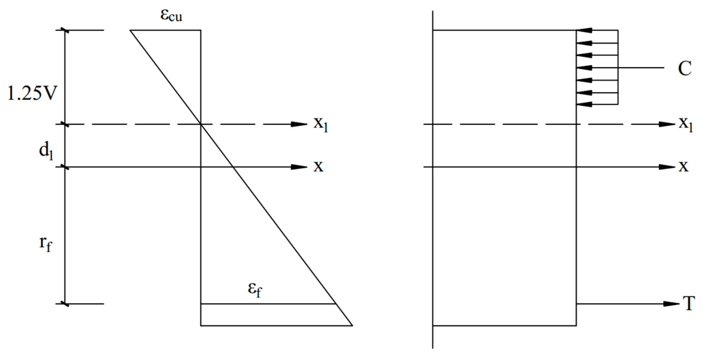
Both GFRP and BFRP are mineral fiber-reinforced materials but have a different density, tensile limit, and modulus. Based on the formula of bearing capacity of GFRP concrete members, the relevant parameters of the formula are modified to obtain the formula of bending capacity of BFRP-reinforced RC. Figure 14 shows the calculation of the flexural load-carrying capacity of the BFRP-reinforced concrete in a circular cross-section. The x-axis is the neutralizer axis of the flexure section; the shaded portion is the simplified concrete rectangle in the compression zone.
As shown in Figure 14, the equation for circle is x2 + y2 = r2, x = rcost, y = rsint (t is the angle between OP and x-axis). The set height of the compression arched area is V = ηr, and the right half of the center of the bow is α = arccos (1 − η). The distance from the neutralizing axis x-x to the edge of the compression zone is V1 = V/β1. Figure 14 shows the area microelement of the arched compression zone is as follows:
The bow area is
The total concrete pressure in the compression zone is
The distance from the centroid of the arch compression zone to the x-axis is
The moment of the total pressure in the bow compression zone to the x-x axis is
Uniform reinforcement throughout the section is shown in Figure 14, so the area of reinforcement is Af. To simplify the calculation, the BFRP are converted to curved sheets with a thickness of . The maximum strain of the concrete at the edge of the compression zone is εcu, and the maximum strain of the BFRP tendon in the tensile zone is assumed to be
where (as seen in Figure 15), the strained BFRP tendon microelement strain is . The microelement area of the circular BFRP strip is .
The total tensile strength of BFRP in the tensile zone is
The total tensile BFRP torque at the x-axis is
Based on the axial force balance and torque balance, the formula to calculate the bending load-carrying capacity of the circular BFRP-reinforced concrete section is
where A is Circle Section Area (mm2); As is section area of longitudinal BFRP bars in total (mm2); r is Radii of circular cross-section (mm); rs is Radii of BFRP (mm); α is the ratio of the rounded corners of the concrete section area in the compression area to 2π (%); αt is ratio of As to AG (section area of longitudinal GFRP bars). If α > 0.625, αt = 0; ffd is the design value of the tensile strength of BFRP (MPa); α1 = 0.92; β is a correction factor that is to be solved.
αt = 1.25 − 2α
4.3. Calculation of the Correction Factor β
The purpose of this paper is to compare the normal limit bearing torque obtained by an indoor test with the bending moment calculated by Equations (10)–(12) and, thus, to solve the problem of unknown parameter β. The calculation formula of the bearing capacity of BFRP-reinforced concrete members is derived, which is in agreement with the experimental results. The bending moments are calculated and measured in Table 8.
It can be seen from the comparison results that the β fit of the bending moment is 2.5, which is almost 50% greater than the bending moment correction coefficient K (K = 1.4) in the GFRP-reinforced concrete circular cross-section bearing capacity calculation method.
4.4. Verification of Calculation Methods
Based on the proposed method for calculating the flexural bearing capacity of BFRP -RC columns and the recommended method in GB50010 [43], ACI440.1R-15 [49], and Zhang et al. [50], the flexural bearing capacity of four columns in this paper was calculated, and the experimental results were compared with the calculated results. The results are shown in Table 9.
It can be seen that the ACI-recommended method underestimates the flexural bearing capacity of BFRP-RC structures, with an average ratio of calculated values to experimental values of 0.89. According to the ACI code, the design value of the mid-span bending moment is about 20% larger than that of the Chinese code; due to the difference in bending moment adjustment coefficients β, Zhang’s method overestimated the flexural bearing capacity of BFRP-RC structures, with an average ratio of 1.85 between the calculated and experimental values. The proposed method in this paper is in good agreement with the experimental values, and the average ratio is 0.998. Compared with other calculation methods, the calculation method proposed can better predict the flexural bearing capacity of BFRP-reinforced concrete columns. At the same time, the influence of different performance characteristic parameters, such as the elastic modulus of BFRP reinforcement, was considered in the establishment of the calculation model.
5. Conclusions
In order to achieve the flexural performance of BFRP-reinforced concrete elements in a circular section, the bonding properties of BFRP and different labeled cement concretes were tested in a lab. And in order to comprehensively study the failure characteristics and load-carrying capability of BFRP-reinforced piles, four kinds of BFRP plies were fabricated, and the mechanical characteristics of the BFRPB were studied during flexion. These results demonstrate the following:
- (1)
- Different types of BFRP and cement substrates have different bond strengths. Generally speaking, the larger the diameter of the bar, the higher the strength of the bond. It is recommended for commonly used diameter engineering anchors that M20 and M30 mortar have a BFRP bond strength of approximately 5–6 MPA and C30 concrete of about 8 MPa.
- (2)
- The positive transverse stress is consistent with the reasonableness of the cross-section hypothesis of circular reinforced concrete BFRP members. The pile load is broken in four stages, and the cracking load is 51% to 67% of the normal limit load. The deformation of the main rod increases with the increase in load but decreases in the pressurized region. This mutation indicates that the concrete in the pressure zone is starting to become plastic, but it still has a high carrying capacity.
- (3)
- According to the calculation method of bending bearing capacity of the GFRP concrete circular pile, the ultimate bearing capacity obtained by the indoor test is compared with that of the calculated test. A formula for calculating the bearing capacity of BFRP-reinforced concrete structures with circular cross-sections is obtained, and the coefficient beta = 2.6 is obtained by experiment. The calculated values have good agreement with test results compared with previously published studies in this field.
Further experimental works are still needed to validate and improve the performance of the proposed model in the near future. Studies on the axial load–strain behavior of BFRP-RC columns with various shapes of cross sections, different types of BFRP reinforcement, different grades of concrete strength, and confined concrete cores are also essential to gain an in-depth understanding of the carrying capacity of BFRP-RC columns. The test outcomes for validating in BFRP-RC columns need to be further assessed.
Author Contributions
Validation, Y.W.; Investigation, Q.P.; Writing—original draft, J.C.; Writing—review & editing, Y.W.; Supervision, Y.L. All authors have read and agreed to the published version of the manuscript.
Funding
Financial support for this investigation was provided by the Ph.D. foundation program of CDTU (No.2023RC048).
Data Availability Statement
All data, models, and code generated or used during the study appear in the submitted article.
Conflicts of Interest
Author Jibin Chen was employed by the company Zhongyan Technology Co., Ltd. Author Yibin Luo was employed by the company China Southwest Geotechnical Investigation & Design Institute Co., Ltd. The remaining authors declare that the research was conducted in the absence of any commercial or financial relationships that could be construed as a potential conflict of interest.
References
- Altalmas, A.; El, R.A.; Abed, F. Bond degradation of basalt fiber-reinforced polymer (BFRP) bars exposed to accelerated aging conditions. Constr. Build. Mater. 2015, 81, 162–171. [Google Scholar] [CrossRef]
- Monaldo, E.; Nerilli, F.; Vairo, G. Basalt-based fiber-reinforced materials and structural applications in civil engineering. Compos. Struct. 2019, 214, 246–263. [Google Scholar] [CrossRef]
- ElMessalami, N.; Abed, F.; El Refai, A. Response of concrete columns reinforced with longitudinal and transverse BFRP bars under concentric and eccentric loading. Compos. Struct. 2021, 255, 113057. [Google Scholar] [CrossRef]
- Kang, J.W.; Zhao, W.; Hu, Y.; Zhou, Q.; Wang, Z. Application of Basalt Fiber and Its Composite Reinforcement in Geotechnical Engineering; China Architecture Press: Beijing, China, 2021. [Google Scholar]
- Hassan, M.; Benmokrane, B.; ElSafty, A.; Fam, A. Bond durability of basalt-fiber-reinforced-polymer (BFRP) bars embedded in concrete in aggressive environments. Compos. Part B Eng. 2016, 106, 262–272. [Google Scholar] [CrossRef]
- Akiel, M.S.; El-Maaddawy, T.; El Refai, A. Serviceability and moment redistribution of continuous concrete members reinforced with hybrid steel-BFRP bars. Constr. Build. Mater. 2018, 175, 672–681. [Google Scholar] [CrossRef]
- At, A.; Wa, B. Bond Durability and Service Life Prediction of BFRP Bars to Steel FRC under Aggressive Environmental Conditions. Compos. Struct. 2021, 269, 114034. [Google Scholar]
- Bao, R.H.; Xiang, D.Z. Experiment Study of BFRP bars’ Mechanical Properties. Appl. Mech. Mater. 2012, 174–177, 830–833. [Google Scholar]
- Wu, G.; Zhu, Y.; Dong, Z.; Wang, X.; Wu, Z. Experimental study on the corrosion resistance performance of BFRP bars in the alkaline environment. China Civ. Eng. J. 2014, 47, 32–41. [Google Scholar]
- Wu, G.; Dong, Z.Q.; Wang, X.; Zhu, Y.; Wu, Z.S. Prediction of Long-Term Performance and Durability of BFRP Bars under the Combined Effect of Sustained Load and Corrosive Solutions. J. Compos. Constr. 2015, 19, 04014058. [Google Scholar] [CrossRef]
- Bai, X.Y.; Jing, D.S.; Wang, H.G. Research status of basalt fiber-reinforced polymer anchor in slope support engineering. Sci. Technol. Eng. 2020, 20, 12702–12710. [Google Scholar]
- Shaikh, F.U.A. Review of mechanical properties of short fibre reinforced geopolymer composites. Constr. Build. Mater. 2013, 43, 37–49. [Google Scholar] [CrossRef]
- Dhand, V.; Mittal, G.; Rhee, K.Y.; Park, S.J.; Hui, D. A short review on basalt fiber reinforced polymer composites. Compos. Part B Eng. 2015, 73, 166–180. [Google Scholar] [CrossRef]
- Lu, Z.; Xian, G. Resistance of basalt fibers to elevated temperatures and water or alkaline solution immersion. Polym. Compos. 2018, 39, 2385–2393. [Google Scholar] [CrossRef]
- John, V.J.; Dharmar, B. Influence of basalt fibers in the mechanical behavior of concrete—A review. Struct. Concr. Suco. 2020, 22, 491–502. [Google Scholar] [CrossRef]
- Cakir, F. Evaluation of mechanical properties of chopped glass/basalt fibers reinforced polymer mortars. Case Stud. Constr. Mater. 2021, 15, e00612. [Google Scholar] [CrossRef]
- GB/T26745-2021; Basalt Fiber Composites for Civil Engineering Structure. China National Standard: Beijing, China, 2021.
- Yu, E.Y.; Yu, T.M.; Zhao, X.; Liao, J.; Ying, K. Effects of basalt fiber powder on mechanical properties and microstructure of concrete. Case Stud. Constr. Mater. 2022, 17, e01286. [Google Scholar] [CrossRef]
- Ding, Z.; Lu, Z.X.; Li, Y. Feasibility of basalt fiber reinforced inorganic adhesive for concrete strengthening. Adv. Mater. Res. 2011, 287–290, 1197–1200. [Google Scholar] [CrossRef]
- Bi, Q.W. Microstructure of Basalt Fiber Reinforced Concrete and Experimental Study on Bearing Capacity of Fiber Reinforced Concrete Beams with BFRP Reinforcement. Ph.D. Thesis, Dalian University of Technology, Dalian, China, 2012. [Google Scholar]
- Jiang, C.; Fan, K.; Wu, F.; Chen, D. Experimental study on the mechanical properties and microstructure of chopped basalt fibre reinforced concrete. Mater. Des. 2014, 58, 187–193. [Google Scholar] [CrossRef]
- El Refai, A.; Abed, F.; Altalmas, A. Bond durability of basalt fiber-reinforced polymer bars embedded in concrete under direct pullout conditions. J. Compos. Constr. 2015, 5, 04014078. [Google Scholar] [CrossRef]
- Ma, H.L.; Cui, C.; Li, X.; Hu, S.L. Study on mechanical properties of steel fiber reinforced autoclaved lightweight shell-aggregate concrete. Mater. Des. 2013, 52, 565–571. [Google Scholar] [CrossRef]
- Sadeghian, P.; Fillmore, B. Strain distribution of basalt FRP-wrapped concrete cylinders. Case Stud. Constr. Mater. 2018, 9, e00171. [Google Scholar] [CrossRef]
- Koroglu, A.; Ozdemir, T.; Usanmaz, A. Comparative study of the mechanical properties of fiber-reinforced denture base resin. J. Appl. Polym. Sci. 2009, 113, 716–720. [Google Scholar] [CrossRef]
- Tang, Y.S.; Cang, J.G.; Yao, Y.D.; Chen, C. Displacement measurement of a concrete bridge under traffic loads with fibre-reinforced polymer-packaged optical fibre sensors. Adv. Mech. Eng. 2020, 12, 168781402091053. [Google Scholar] [CrossRef]
- Tang, Y.S.; Jiang, T.F.; Wan, Y. Structural monitoring method for RC column with distributed self-sensing BFRP bars. Case Stud. Constr. Mater. 2022, 17, e01616. [Google Scholar] [CrossRef]
- Chai, L.J.; Guo, L.P.; Chen, B.; Carpinteri, A.; Scorza, D.; Vantadori, S. Effects of BFRP Bar Diameter and Cover Thickness on Fracture Behavior of BFRP Bar–Reinforced Ecological High-Ductility Cementitious Composites. J. Test. Eval. 2021, 49, 4086–4101. [Google Scholar] [CrossRef]
- Zhou, R.; Zhou, F.; Du, Y.; Liao, B.; Feng, G.; Zhu, D. Effect of seawater on bond performance between BFRP bars and seawater sea-sand concrete. Constr. Build. Mater. 2024, 415, 135050. [Google Scholar] [CrossRef]
- He, W.D. Static and Fatigue Ehavior of RC Flexural Members Strengthened with BFRP Grids. Ph.D. Thesis, Southeast University, Nanjing, China, 2021. [Google Scholar]
- Jin, L.; Zheng, M.; Zhang, R.; Du, X. Investigation on the Impact Response of Concrete Beams Reinforced with Hybrid Steel–BFRP Bars. J. Compos. Constr. 2024, 4, 04023029. [Google Scholar] [CrossRef]
- Wang, X.; Zhao, X.; Wu, Z. Fatigue degradation and life prediction of basalt fiber-reinforced polymer composites after saltwater corrosion. Mater. Des. 2019, 163, 107529. [Google Scholar] [CrossRef]
- Song, K.J.; Yu, Y.; Liu, Y.T.; Zhao, J. Flexural Performance Study of Basalt-Fiber-Reinforced Polymer Bar Basalt-Fiber-Reinforced Concrete Beams. Buildings 2023, 13, 2583. [Google Scholar] [CrossRef]
- Wang, D.; Ju, Y.; Shen, H.; Xu, L. Mechanical Properties of High Performance Concrete Reinforced with Basalt Fiber and Polypropylene Fiber. Constr. Build. Mater. 2019, 197, 464–473. [Google Scholar] [CrossRef]
- Liu, Y.; Zhu, Q.; Teng, J.H. Bond Performance of Anti-Corrosion Bar Embedded in Ceramsite Concrete in Freeze–Thaw Cycles and Corrosive Environments. Buildings 2023, 13, 884. [Google Scholar] [CrossRef]
- Shi, J.; Zhu, H.; Wu, Z. Bond Behavior between Basalt Fiber–Reinforced Polymer Sheet and Concrete Substrate under the Coupled Effects of Freeze-Thaw Cycling and Sustained Load. J. Compos. Constr. 2013, 17, 530–542. [Google Scholar] [CrossRef]
- Sagar, B.; Sivakumar, M.V.N. Performance evaluation of basalt fibre-reinforced polymer rebars in structural concrete members—A review. Innov. Infrastruct. Solut. 2021, 6, 75. [Google Scholar] [CrossRef]
- Abushanab, A.; Alnahhal, W.; Farraj, M. Experimental and finite element studies on the structural behavior of BFRC continuous beams reinforced with BFRP bars. Compos. Struct. 2022, 2, 281. [Google Scholar] [CrossRef]
- JTG/T776.4; Basalt fiber and Its Products for Highway Engineering. China National Standard: Beijing, China, 2010.
- DB22T2797.1; Design and Construetion Code for Basalt Fiber Composite Rebar and Basalt Fiber Reinforced Concrete. Jilin Local Standard: Jilin, China, 2017.
- GB/T 10120; Metallic Materials-Stress Relaxation Test. China National Standard: Beijing, China, 1996.
- GB/T232; Metallic Materials-Bend Test. China National Standard: Beijing, China, 2010.
- GB50010; Code for Design of Concrete Structures. China National Standard: Beijing, China, 2010.
- JGJ94; Technical Code for Building Pile Foundation. China National Standard: Beijing, China, 2008.
- GB50330; Technical Code for Building Slope Engineering. China National Standard: Beijing, China, 2013.
- DBJ51/T175; Technical Standard for Application of Basalt Fiber and Its Composite Materials in Sichuan Province. Sichuan Local Standard: Chengdu, China, 2022.
- CJJ 192; Technical Specification for Shield-Cuttable Concrete Reinforcement. China National Standard: Beijing, China, 2012.
- Liang, S.; Zhao, W.; Hu, Y. Experimental Investigation of Flexural Behavior of Cylindrical Member of BFRP Reinforced Concrete. Railw. Eng. 2018, 12, 110950. [Google Scholar]
- American Concrete Institute. Guide for the Design and Con-Struction of Structural Concrete Reinforced with FRP bars:ACI 440. 1R-2015; American Concrete Institute: Farmington Hills, MI, USA, 2015. [Google Scholar]
- Zhang, J.Z.; Pang, Z.Y.; Shen, H. Calculation of the Flexural Capacity of GFRP-reinforced Concrete with Circular Section. Chin. J. Undergr. Space Eng. 2013, 6, 1304–1309. [Google Scholar]
Figure 1.
The BFRP used in the test.

Figure 2.
Basic mechanical properties test.

Figure 3.
A brief schematic of Adhesion performance test.

Figure 4.
Test process and device.

Figure 5.
Component reinforcement diagram.


Figure 6.
RC piles with BFRP bars.

Figure 7.
Test device.

Figure 8.
Relation curve of bond strength between reinforcement and cement-based materials.

Figure 9.
Experimental failure process of basalt-reinforced concrete pile.

Figure 10.
The tensile stress variation curve of BFRPB.

Figure 11.
Stress curve of main tendon of test pile.

Figure 12.
The stress curve of the component section.


Figure 13.
The pile deflection–load curve.

Figure 14.
Section calculation graph.

Figure 15.
Stress–strain calculation schematic.

Table 1.
Physico-mechanical parameters of BFRP (mean value).
| Parameters | 8 mm | 10 mm |
|---|---|---|
| Tensile strength (MPa) | 1139.4 | 1111.9 |
| Shear strength (MPa) | 120 | 159 |
| Retention rate of acid–base corrosion resistance (%) | 92.6 | 96 |
| Creep relaxation for 100 h (%) | 3.867 | 4.427 |
| Bending test (Bend damage angle°) | 49.3 | 45.4 |
Table 2.
Type and ratio of cement base.
| Type of Cement Base | Combination Ratio per Cubic Meter | Cement Model |
|---|---|---|
| Mortar (M20) | Cement/Sands/Water = 1:5:0.8 | 42.5 |
| Mortar (M30) | Cement/Sands/Water = 1:3.1:0.6 | 42.5 |
| Concrete (C30) | Cement: Sands/Aggregate/Water = 1:1.5:3.2:0.5 | 42.5 |
Table 3.
Test pile reinforcement scheme.
| No. | Section Size (mm) | Reinforcement | Reinforcement Ratio | Spacing of Reinforcement (mm) | Protection Layer Thickness (mm) |
|---|---|---|---|---|---|
| 1 | φ200 | 6φ8 | 0.96% | 48 | 40 |
| 2 | φ200 | 6φ10 | 1.5% | 45 | 40 |
| 3 | φ200 | 10φ8 | 1.6% | 26.6 | 40 |
| 4 | φ200 | 14φ8 | 2.24% | 16.9 | 40 |
Table 4.
Adhesion performance test data—Mortan (M20).
| Model of Reinforcement (mm) | Stressed Area (mm2) | Sample 1 | Sample 2 | Sample 3 | Mean Value | |
|---|---|---|---|---|---|---|
| 8 | 1005.31 | Anchoring force (N) | 5024.3 | 6156.4 | 4888.2 | 5356.3 |
| Bond strength (MPa) | 5.00 | 6.12 | 4.86 | 5.33 | ||
| 10 | 1570.80 | Anchoring force (N) | 9196.6 | 9232.6 | 6636.4 | 8355.2 |
| Bond strength (MPa) | 5.86 | 5.88 | 4.23 | 5.33 |
Table 5.
Adhesion performance test data—Mortan (M30).
| Model of Reinforcement (mm) | Stressed Area (mm2) | Sample 1 | Sample 2 | Sample 3 | Mean Value | |
|---|---|---|---|---|---|---|
| 8 | 1005.31 | Anchoring force (N) | 7144.5 | 4590.5 | 6044.4 | 5926.5 |
| Bond strength (MPa) | 5.01 | 4.78 | 4.91 | 4.90 | ||
| 10 | 1570.80 | Anchoring force (N) | 7872.5 | 7500.3 | 7716.5 | 7696.4 |
| Bond strength (MPa) | 7.11 | 4.57 | 6.01 | 5.90 |
Table 6.
Adhesion performance test data—concrete (C30).
| Model of Reinforcement (mm) | Stressed Area (mm2) | Sample 1 | Sample 2 | Sample 3 | Mean Value | |
|---|---|---|---|---|---|---|
| 8 | 1005.31 | Anchoring force (N) | 8321.8 | 9624.6 | 8800.6 | 8915.67 |
| Bond strength (MPa) | 6.64 | 5.33 | 7.73 | 6.57 | ||
| 10 | 1570.80 | Anchoring force (N) | 10,425 | 8368.5 | 12137 | 10,310.17 |
| Bond strength (MPa) | 8.28 | 9.57 | 8.75 | 8.81 |
Table 7.
Results of pile bearing capacity test.
| No. | Reinforcement | Reinforcement Ratio/ρsf | Initial Cleavage | Normal Use Status | Disruption | |||
|---|---|---|---|---|---|---|---|---|
| Load kN·m | Curvature mm | Load kN·m | Curvature mm | Load kN·m | Curvature mm | |||
| 1# | 6φ8 | 0.96% | 5.04 | 1.9 | 7.5 | 6 | 12.6 | 11.2 |
| 2# | 6φ10 | 1.50% | 5.04 | 2.0 | 9.0 | 6 | 22.7 | 21.2 |
| 3# | 10φ8 | 1.60% | 5.04 | 1.9 | 9.8 | 6 | 12.6 | 10.1 |
| 4# | 14φ8 | 2.24% | 2.5 | 1.0 | 10.3 | 6 | 17.6 | 8.7 |
Table 8.
Calculation and measurement of bending moment.
| No. | Calculation (kN·m) | Measurement (kN·m) | Ratio | Average |
|---|---|---|---|---|
| 1 | 9.66 | 3.75 | 2.576 | 2.502 |
| 2 | 11.48 | 4.5 | 2.551 | |
| 3 | 12.04 | 4.875 | 2.469 | |
| 4 | 13.58 | 5.625 | 2.414 |
Table 9.
Comparison between experimental and theoretical values of flexural capacity of BFRP-RC columns.
Table 9.
Comparison between experimental and theoretical values of flexural capacity of BFRP-RC columns.
| Data Sources | Specimens | Reinforcement | ρsf% | ME | MP | MC | MA | MZ | MM/ MP | ME/ MC | ME/ MA | ME/ Mz |
|---|---|---|---|---|---|---|---|---|---|---|---|---|
| This paper | 1 | 6φ8 | 0.96 | 3.75 | 3.86 | 2.22 | 2.78 | 7.16 | 0.97 | 1.69 | 1.35 | 0.52 |
| 2 | 6φ10 | 1.50 | 4.5 | 4.61 | 3.53 | 4.25 | 8.50 | 0.98 | 1.27 | 1.06 | 0.53 | |
| 3 | 10φ8 | 1.60 | 4.875 | 4.82 | 3.29 | 4.39 | 8.92 | 1.01 | 1.48 | 1.11 | 0.55 | |
| 4 | 14φ8 | 2.24 | 5.625 | 5.43 | 4.60 | 5.68 | 10.05 | 1.04 | 1.22 | 0.99 | 0.56 |
Notes: ME is the experimental flexural capacity (kN·m); MP is the flexural capacity calculated by the proposed method (kN·m); MC is the theoretical flexural capacity calculated by GB50010 code (kN·m); MA is the flexural capacity calculated by ACI code (kN·m); MZ is the flexural capacity calculated by Zhang, J.Z. (kN·m).
Disclaimer/Publisher’s Note: The statements, opinions and data contained in all publications are solely those of the individual author(s) and contributor(s) and not of MDPI and/or the editor(s). MDPI and/or the editor(s) disclaim responsibility for any injury to people or property resulting from any ideas, methods, instructions or products referred to in the content. |
© 2024 by the authors. Licensee MDPI, Basel, Switzerland. This article is an open access article distributed under the terms and conditions of the Creative Commons Attribution (CC BY) license (https://creativecommons.org/licenses/by/4.0/).
Share and Cite
MDPI and ACS Style
Chen, J.; Pan, Q.; Wei, Y.; Luo, Y. Experimental Study on Flexural Behavior of RC Piles with Basalt Fiber-Reinforced Polymer Bars and Load Carrying Capacity Calculation. Buildings 2024, 14, 1328. https://doi.org/10.3390/buildings14051328
AMA Style
Chen J, Pan Q, Wei Y, Luo Y. Experimental Study on Flexural Behavior of RC Piles with Basalt Fiber-Reinforced Polymer Bars and Load Carrying Capacity Calculation. Buildings. 2024; 14(5):1328. https://doi.org/10.3390/buildings14051328
Chicago/Turabian StyleChen, Jibin, Qiang Pan, Yao Wei, and Yibin Luo. 2024. "Experimental Study on Flexural Behavior of RC Piles with Basalt Fiber-Reinforced Polymer Bars and Load Carrying Capacity Calculation" Buildings 14, no. 5: 1328. https://doi.org/10.3390/buildings14051328
Note that from the first issue of 2016, this journal uses article numbers instead of page numbers. See further details here.