

Experimental Investigation and Numerical Analysis of the Axial Load Capacity of Circular Concrete-Filled Tubular Columns


Faculty of Civil Engineering, The University of Belgrade, Bulevar Kralja Aleksandra 73, 11000 Belgrade, Serbia
*
Author to whom correspondence should be addressed.
Buildings 2024, 14(5), 1329; https://doi.org/10.3390/buildings14051329
Submission received: 8 April 2024
/
Revised: 26 April 2024
/
Accepted: 29 April 2024
/
Published: 8 May 2024
(This article belongs to the Special Issue Advances in Steel–Concrete Composite Structures)
Abstract
:This paper focuses on the experimental investigation of the axial load capacity of CFT (concrete-filled steel tube) columns under actual construction conditions during building reconstruction. A total of four samples were loaded up to failure. The varied parameters were the column length and absence/presence of the concrete infill within the steel tube. Further, the analysis is extended to developing a numerical model in the finite element-based software ABAQUS version 6.9. This numerical model includes material and geometrical nonlinearities and was validated with the experimental results. The contribution of the concrete core to the column capacity and the concrete core confinement effect are discussed. Finally, the column capacity was calculated according to several design codes: the Eurocode 4 with and without considering the confinement effect, American specifications, Australian standards, the American Institute of Steel Construction, and the Architectural Institute of Japan. The Eurocode 4 considering the confinement effect provides the closest results to those obtained in the tests.
1. Introduction
Due to their constructive advantages, columns derived from steel hollow profiles filled with concrete (CFT columns) have found wide application in engineering practice. Compared to traditional concrete or steel columns, the advantages of these columns are numerous: higher load capacity, rigidity and ductility, and savings in space, material, and construction time.
Determining the ultimate bearing capacity of CFT columns is challenging due to many parameters which need to be investigated. First, the nonlinear behavior of the constitutive materials, steel and concrete, needs to be defined for application in numerical analysis. Further, the study should include the steel profile’s second-order influences, geometric imperfections, and residual stresses. Calculating the bearing capacity of CFT columns by current design codes and provisions uses simplified methods and is based on the calculation according to limit states.
In recent years, many authors have published works on the experimental and numerical analysis of the bearing capacity of CFT columns. Numerical analyses are mostly conducted using available finite element method (FEM) software. The majority of studies employed ABAQUS, as in [1,2,3,4], while certain studies utilized ANSYS [5,6,7] or LS-DYNA [8,9,10]. Further, many researchers provided a comparative analysis of their results with current design codes. The accuracy of calculating the bearing capacity of CFT columns is significantly affected by the adopted constitutive models for concrete and steel. Whole series of proposals for these relationships that more or less accurately describe the behavior of concrete and steel can be found in the literature [3,11,12,13,14,15,16,17]. Schneider [11] analyzed the influence of the section shape of the hollow steel profile and the steel quality on the CFT column load capacity on fourteen samples. Ehab Ellobody et al. [3] proposed constitutive models for confined concrete and steel for ABAQUS use. The numerically obtained results of the axial bearing capacity of CFT columns are compared with the results of experiments, as well as with the following design codes: EC4, ACI, and AISC. Giakoumelis and Lam [18] examined the effect of wall thickness, bond behavior of the hollow steel profile and concrete core, concrete shrinkage, and creep on the axial load capacity of circular CFT columns. In the paper [13], Hu proposed a constitutive model for the concrete core inside the CFT column, separately for circular and square sections. Liang and Fragomeni [19] presented constitutive models for the concrete and steel of normal- and high-strength materials. They conducted a parametric analysis to determine the influence of concrete confinement by the steel profile, the diameter-to-wall thickness ratio of the steel profile D/t, and the impact of concrete strength and steel quality on the bearing capacity of the CFT column of the circular section. Li et al. [20] analyzed the fundamental behavior of high-strength concrete-filled high-strength square steel tubular (HCFHSST) long columns under eccentric compression. Lin et al. [16] developed a new fiber beam element (FBE) model that applies to both small and large CFT and slender columns. Finally, attention should also be directed towards exploring new solutions and approaches, including innovative materials and sustainable solutions [21,22,23,24,25].
The CFT column’s slenderness, defined as the column length-to-dimeter ratio L/D, significantly influences its bearing capacity [26,27,28,29]. In the case of short columns (L/D ≤ 3.00) [26,30] the loss of bearing capacity may occur due to failure in the concrete material or yield of the steel profile.
The concrete core confinement effect-related research can be found in [18,19,31,32,33,34]. During the axial load, the inner concrete core gets strengthened by an outer steel profile that affects the bearing capacity of a composite column. This confinement decreases with the increased diameter-to-profile thickness ratio D/t, or with concrete strength, column slenderness, and load eccentricity. On the contrary, it rises with higher steel quality.
Oliveira et al. [26] presented experimental results from 32 axially loaded CFT columns, where the load was applied solely on the concrete core to assess the passive confinement provided by the steel tube. Abed et al. [35] conducted experimental and numerical studies on 16 CFT specimens, identifying the most influential factor on compressive behavior as D/t. Tao et al. [1] proposed an expression for determining lateral pressure in circular columns based on numerical tests with varying parameters. Han et al. [36] introduced the confinement factor, which relies on the cross-sectional areas and strengths of steel and concrete. However, instructions in the literature regarding when and how to consider confinement remain ambiguous today. This is partly due to challenges in direct measurement in experiments, leading some authors to provide algorithms for estimating this strengthening effect.
When creating a numerical model of the CFT column in ABAQUS, the bond behavior of two surfaces in a composite element should be defined. This contact is formed at the connection of the inner steel profile surface and the outer concrete core surface. This connection can be modeled using gap elements representing contact behavior in the longitudinal and tangential directions. It can be defined by setting the appropriate friction coefficient in the range of 0.2–0.6 [3,13,19]. The bond between the concrete core and the hollow steel profile decreases with increasing concrete strength [26,27]. This phenomenon occurs since higher-strength concrete has more significant shrinkage [3].
This research aimed to perform experimental tests on CFT columns on an actual reconstruction site to validate previous design calculations. Generally, there is a need for studies dealing with an empirical investigation conducted in conditions that may significantly differ from those achieved in laboratory settings. Moreover, this data may be valuable for validating other laboratory-performed tests or numerically obtained results. Finally, this study aimed to define a numerical 3D model which would successfully predict the structural behavior of a circular section’s axially loaded CFT column with reasonable accuracy. Nonlinear numerical analysis was performed in ABAQUS [37] using the proper concrete core and steel profile constitutive models, and aimed to include concrete confinement. The results of the study were validated with test results and compared with the relevant design codes: the EN-1994-1-1 (EC4) with and without considering the confinement effect [38], American specifications (ACI) [39], Australian standards (AS) [40,41], the American Institute of Steel Construction (AISC) [42], and the Architectural Institute of Japan (AIJ) [43]. Besides, design codes offer diverse instructions and criteria on how to account for the confinement effect. For instance, EC4 utilizes relative column slenderness, whereas AIJ employs the length-to-diameter (L/D) ratio.
The study introduces an experimental program designed to assess the axial load capacity of CFT columns under real construction conditions. The primary objective was to evaluate the effectiveness of concrete infill and steel tube confinement in strengthening the columns. Key parameters under investigation included column length and the impact of concrete infill on axial load capacity. The study tested the axial bearing capacity of four specimens: two hollow steel profiles with a D/t ratio of 101.6/2.7 mm and lengths of 0.5 m and 1.0 m, and two CFT columns consisting of identical steel profiles filled with C25/30 concrete. This approach allowed for measurement of the contributions of concrete infill and the calculation of steel tube confinement.
2. Experimental Research Program
2.1. Test Setup
The axial load capacity of steel and CFT columns was tested using a particular constructed set (Figure 1). It consists of a steel frame 2400 × 600 × 600 mm with two hydraulic 200 mm diameter presses. Hydraulic presses are driven by two electric motors (power 7 kW and 10 kW) with two hydraulic pumps (for lower and higher pressure). The total capacity of the press is 300 bar. The force was continuously measured using the C6A2MN dose device, which can measure a load of up to 2000 kN with an accuracy of ±0.1 kN. The column shortening was continuously measured with the W100 displacement gauge (inductive standard displacement transducer), which can measure the vertical displacement or shortening of the column with an accuracy of ±0.01 mm. Four gauges are placed on the top of the circular specimen in two perpendicular directions.
During the column’s concreting, the concrete core was left 1–2 cm longer than the steel profile and finely aligned with a concrete grinder on the testing day. The load was applied in steps via a rigid plate welded to the bottom and top ends of the steel column and the CFT column. This way, the load was applied simultaneously to the steel and concrete part of the column cross-section. The load applied in the tests was a quasistatic monotonically increasing centric axial load. A calotte device was used to achieve the centric introduction of the load. The loading process can be considered short-term as each sample’s failure took about 3 min.
The axial load capacity of four specimens was tested: two hollow steel profiles denoted as S1 and S2 and two CFT columns denoted as C1 and C2, as in Table 1. The ultimate load capacity of the steel columns and the corresponding CFT columns was analyzed, and the concrete infill’s contribution to the load capacity was eventually determined.
The specimen D/t ratio of all specimens was 37.63. The steel was S355 quality, and its characteristics were taken from the material specification. CFT column specimens C1 and C2 have the same length and steel characteristics as their empty reference columns S1 and S2. The concrete infill was C25/30 with a three-fraction granulometric composition made at the concrete plant. The specimen testing was performed on the construction site. The old “NAPRED” building in Belgrade was reconstructed using specifically CFT columns. The specimens were concreted in several layers and slumped with a metal rod. The concrete compressive strength was checked for three control cylinder samples 150 mm·300 mm, and the mean value fc′ was 30.5 MPa.
A rigid steel plate at the bottom end of the specimens was also welded to the testing set. This way, the displacements and rotations of the samples are prevented by simulating fixed-end conditions. A rigid steel plate at the upper end of the specimen was also welded to the inner frame of the testing set to avoid rotation but allow movement in the loading direction. According to EC4 [38], the relative slenderness of the column was calculated using the following expression:
where Npl,Rk is the characteristic value of the plastic resistance of the composite section to the compressive normal force, and Ncr is the elastic critical normal force. The relative slenderness of the specimens is also shown in Table 1.
2.2. Failure Modes and Results
The axial load capacities of the four specimens obtained in tests Ntest are reported in Table 1. Figure 2a shows the 0.5 m long hollow specimen S1 and CFT column C1 failure pattern. In these tests, the failure occurred due to the yielding of the steel profile and outward local buckling at both ends of the steel tube. Figure 2b shows the 1.0 m long hollow specimen S2 and CFT column C2 after testing. Here, the failure also occurred due to the outward local buckling of the steel profile at both ends of the column. The tests concluded once the pressure on the manometer began to decrease. At the same time, significant deformations in the steel tube were noted. Additionally, post-failure, the steel tubes of the CFT column specimens C1 and C2 were sectioned to inspect the inner concrete core. It was affirmed that the failure resulted from the yielding of the steel tube, as no evidence of concrete crushing was detected within the core. For longer specimens, besides the yielding of the steel tube, the signs of the overall column’s buckling could also be observed.
3. Numerical Modeling of Axial Bearing Capacity of CFT Columns Using FEM
3.1. General
The axial load capacity of circular CFT columns was determined using the finite element method-based software ABAQUS version 6.9 [37] (Figure 3). Three-dimensional C3D8R finite elements (8-node linear brick, reduced integration with hourglass control) were used for the concrete core. S4R finite shell elements (4-node general-purpose shell, reduced integration with hourglass control, finite membrane strains) were used to model the steel profile. An element size of 10 mm was chosen for both concrete and steel components based on the mesh sensitivity analysis [2]. The material nonlinear stress–strain relations are included within the constitutive materials. Finally, the connection of the steel profile with the concrete core was modeled using “surface-to-surface contact” elements [37].
The nonlinear analysis uses Newton’s direct method with a maximum of ten increments. The initial increment size is 0.1, the minimum increment size is 0.0001, and the maximum is 1.0. A linear extrapolation of the previous increment is adopted at the beginning of the next increment. The load was applied as a surface load in steps equivalent to the test’s applied pressure. The boundary conditions match the conditions from the experiment. At the bottom end of the CFT column, translation and rotation in all three directions are restrained, representing a rigid fastening. To apply the axial load, only vertical translation of the column is allowed at the upper end of the CFT column.
3.2. Constitutive Model for Concrete
The constitutive model for concrete significantly influences the accuracy of the obtained results. The model applied in this study was recommended by [3] (Figure 4), and it presents stress–strain (σ–ε) diagrams for both unconfined and confined concrete. The confined concrete model incorporates an increase in peak compressive concrete strength as well as improved ductility due to the presence of the steel casing.
The uniaxial compressive strength of unconfined concrete fc′ was obtained in control tests as 30.5 MPa. The corresponding strain εc’ is taken as 0.003. The stress–strain relation of unconfined concrete is taken as linear until the value of 0.5·fc′. The modulus of elasticity of concrete Ec is determined according to EN 1992-1-1 [44] based on the following expression:
The nonlinear part of the σ–ε diagram for unconfined concrete beyond 0.5·fc′ is defined by the following equation, initially proposed by the author [45]:
where RE and R are coefficients calculated as follows:
where Rσ and Rε in (5) equal 4 [46].
The tensile strength of concrete is taken as approximately 9% of the compressive strength of concrete fc′. After reaching the peak value, the tensile stress decreases to zero at the strain of 0.001 [37].
The confinement effect significantly influences the axial bearing capacity of short circular CFT columns [30,47]. At the initial loading level, the influence of the steel part of the section on the concrete part is small, considering that steel has a higher Poisson coefficient. At an axial strain of approximately 0.001, micro-cracks appear in concrete, with the transverse strains in the concrete growing rapidly [48]. With a further increase in the load, the concrete gets strengthened by the steel profile. Consequently, the steel part of the section is in a biaxial stress state, while the concrete is in a triaxial stress state. It is known that the compressive strength of concrete increases in this condition. When this strengthening effect is considered, the CFT column’s load capacity is greater than the sum of the load capacity of the individual column elements.
To generate the σ–ε diagram of confined concrete, the previous Ec, fc′, and εc′ defined in Equations (2)–(5) are replaced with a modulus of elasticity of confined concrete Ecc, compressive strength of confined concrete fcc′, and the corresponding strain εcc′ [3,13,49], defined by the following expressions [50]:
where k1 and k2 are coefficients 4.1 and 20.5, respectively [51], while fl is the lateral confining pressure, which depends on the ratio D/t and on the yield strength of steel fy. It can be calculated in the following way [13]:
The decreasing branch of the confined concrete diagram is linear in the interval from εcc′ to 11∙εcc′. The reduction coefficient k3 depends on the ratio D/t and the fy and can be calculated as follows [13]:
while r is the reduction coefficient that depends on the class of concrete. The reduction coefficient for concrete type C25/30 is 1.00 [13].
3.3. Constitutive Model for Steel
The von Mises model with isotropic hardening was applied in the paper. Figure 5 shows the adopted constitutive uniaxial model for structural steel [54].
Here, fy is the yield strength 355 MPa for S355 steel quality, εy is the corresponding strain, fu is the ultimate strength 490 MPa, and εu is the corresponding ultimate strain. Young’s modulus of elasticity of steel is 210 GPa, while Poisson’s ratio is 0.3.
3.4. The Connection between the Concrete Core and the Steel Profile
The bond connection of the steel profile with the concrete core can be modeled using “surface-to-surface contact” elements [11]. The model uses contact elements that simulate the behavior of the connection in the longitudinal and tangential directions. The first is defined using the “Hard Contact” option available in ABAQUS. It allows separation of the contact surfaces in tension but prevents penetration of materials in compression. For the tangential direction, the “Columb friction model” was adopted, whereby the coefficient of friction was set at 0.47 [55]. According to numerous authors, this coefficient is usually in the range of 0.2–0.6 [3,13,19], although it has little impact on axial response [2].
3.5. Numerical Results
The failure of both samples C1 and C2 occurred due to the yielding of the steel profile, and the axial load capacities NFEM are reported in Table 1. The ultimate axial strength obtained for the C1 is 697.52 kN. The ultimate strength sustained by the steel part of the column can be obtained by integrating the stress along the steel part in the cross-section. As it equals 329.10 kN, it was evident that the contribution of the concrete filling to the load capacity of the column was 53%. The compressive strength of the confined concrete is fcc′ = 50.69 MPa. In this case, the lateral confining pressure is fl = 4.92 MPa. The stress results for the specimen C1 are shown in Figure 6a.
The ultimate axial strength obtained for the C2 specimen is 568.65 kN, while the strength sustained by the steel part of the column is 328.09 kN. The contribution of the concrete infill to the bearing capacity of the column is 42%, meaning that the strength of the confined concrete is fcc′ = 33.10 MPa. In this case, the lateral tension pressure is fl = 0.63 MPa. The stress results for the specimen C2 calculations are shown in Figure 6b.
4. Validation of Results
4.1. Comparison of N-ε Relations and Ultimate Strength Capacity Obtained in Tests and FEM
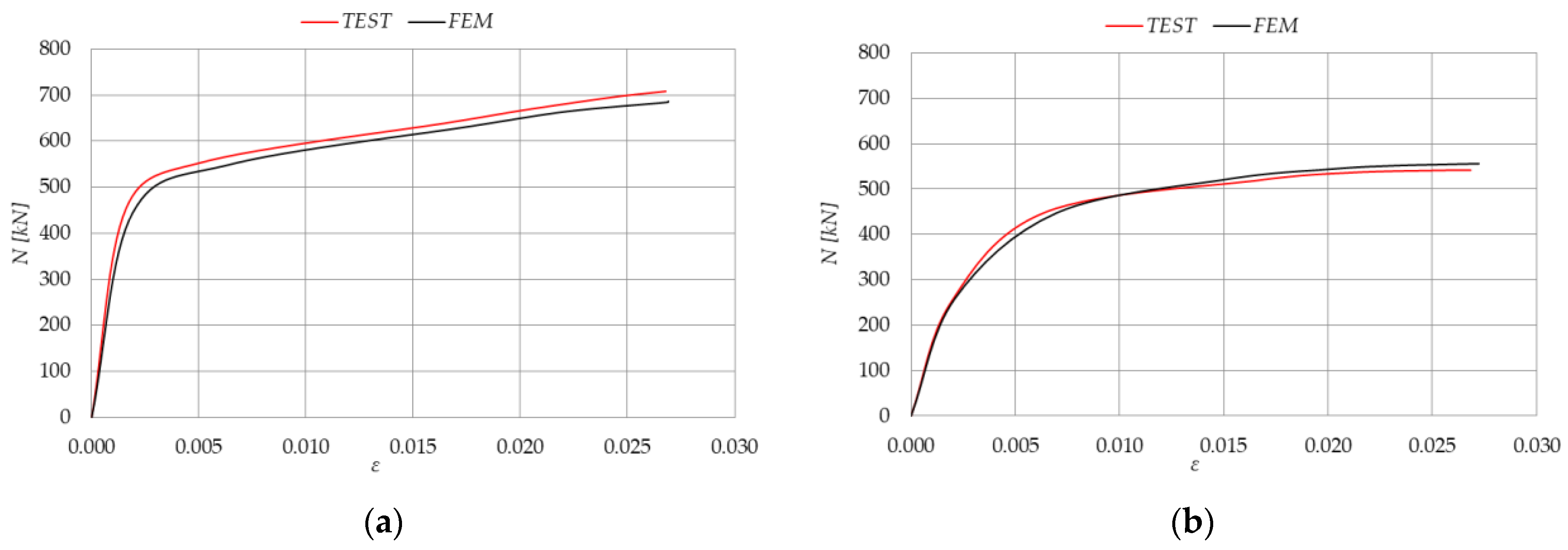
To validate the model presented in chapter 3 calculated using FEM, the results were compared with the experimental results. Figure 7 shows the ultimate force N-ε strain response for CFT specimens C1 and C2. A good agreement between the results can be observed. For CFT column C1, the ultimate force NFEM obtained by ABAQUS is 0.6% lower than the limit force obtained by experimental research. In Figure 7a, the axial force increases approximately linearly to about 400 kN and 0.0025 strain. With a further load increase, the specimen demonstrates plastic behavior with hardening and high strain levels achieved. For CFT column C2, the ultimate force NFEM is 2.3% higher than Ntest. However, the inelastic behavior of the column occurs much earlier, at a force of about 200 kN and a strain of approximately 0.001, as shown in Figure 7b. This occurs because of the column’s global instabilities.
Moreover, it can be concluded that the column’s length significantly influences the axial load capacity of the CFT column. With a double increase in the column length from 0.50 m to 1.00 m, the limit force of the CFT column decreases 1.26 times.
4.2. Comparison of Steel Profile Contribution and Confinement Effect
Based on the results of the experimental tests, the ultimate axial capacity of steel column S1 and CFT column C1 are 315.78 kN and 701.71 kN, respectively. Based on these results, it can be concluded that the contribution of the concrete core to the load capacity of the column is 55%. Thus, the compressive strength of the concrete, initially measured at 30.5 MPa, increased to 53.10 MPa due to confinement provided by the outer steel tube. For the accepted value of k1 = 4.1, the lateral confining pressure fl according to Equation (6) is 5.51 MPa. A good agreement of the results can be observed considering the following:
Similarly, based on the results of the experimental tests, the ultimate axial capacity of steel column S2 is 297.84 kN, while the capacity of CFT column C2 is 555.57 kN. The concrete infill contribution to the column’s total load capacity is 46.4%. The strength of the confined concrete increased to 35.46 MPa, so the lateral confining pressure is 1.21 MPa. A good agreement between the results can also be noted, given the following:
Finally, the lateral confining pressure fl registered for specimens C1 and C2 as 0.5 m and 1.0 m long, respectively, is compared in Equation (13). As also previously reported in the literature, it is confirmed that concrete confinement has a greater influence in shorter rather than in slender CFT columns, and so should be taken into account.
4.3. Comparison of the Obtained Results with Current Design Codes
Table 3 and Table 4 show the comparison of experimental results NTEST, results obtained in ABAQUS NFEM for CFT specimens C1 and C2 with the N values calculated by the following design codes: EC4, EC4 considering the confinement, ACI/AS, AICS, and AIJ. Unit partial safety factors for the material are adopted.
Following the EC4 [38], the plastic resistance to compression Npl,Rd of a composite cross-section should be calculated by adding the plastic resistances of its components as follows:
where Aa, Ac, and As are the cross-sectional area of the steel profile, concrete, and reinforcement, respectively, and fyd = fy/γa, fsd = fsk/γs, and fcd = fck/γc are the corresponding design values of the yield strength for steel and reinforcement and the compressive strength of concrete; fy, fsk, and fck are their characteristic values; γa, γs, and γc are the recommended values of the partial safety coefficients for the corresponding materials provided in EC2 [44] and EC3 [56], but here for validation all are taken as unity.
According to EC4, in the case of circular hollow steel profiles filled with concrete, the increase in concrete strength under pressure caused by the confining of the concrete by the steel profile can be taken into account if the following conditions are met [38]: relative slenderness , , where e is the load eccentricity. In that case, the plastic resistance to compression Npl,Rd of a composite cross-section should be calculated as follows:
Coefficients ηc and ηa include the concrete confinement effects introduced and depend on the relative slenderness and e/D ratio [16].
Applying ACI [39] and AS [40,41] the resistance to compression of the CFT column cross-section is also calculated without appropriate safety factors for the materials (unfactored axial bearing capacity) and is given by the following expression:
As per AISC [42], the resistance of the cross-section under axial pressure is determined based on the following expression:
where C is the strength factor for concrete, and the rectangular CFT column amounts to 0.85·fck, while for the circular CFT column, 0.95·fck.
AIJ suggests the following expression for determining the ultimate bearing capacity of the cross-section of a CFT column under axial pressure [43]:
where fcyl,100 is the compressive strength of concrete tested on a cylinder sample with dimensions of 100 mm·200 mm, and η is the coefficient that considers the confinement effect and is 0.27. The confining effect can be considered if the following condition is met: .
It can be observed that for a CFT column C1, the EC4, taking into account the confinement effect, gives the closest results to the results obtained by experimental testing. On the other hand, the ACI/AS regulations give the most conservative results.
For a CFT column C2, the confinement effect is significantly lower due to the increase in column slenderness. In this case, the ultimate value of the axial force of the CFT column obtained by experimental testing is lower than the calculated value proposed by EC4, considering the confinement effect. However, the same value NEC4, conf again gives the closest results to the results of the experimental tests, while the ACI/AS norms provide the most conservative results.
5. Conclusions
This paper presents the experimental investigation of the CFT column’s axial capacity under construction conditions. The influence of the column’s length, the concrete infill on the total bearing capacity of the CFT column, and the concrete confinement effect were analyzed experimentally and numerically.
Using the developed numerical models in the finite element-based software ABAQUS, it is possible to determine the bearing capacity of CFT columns with satisfactory accuracy, considering geometric and material nonlinearities. The differences between the ultimate limit force of the CFT column obtained in FEM models and tests are within 0.6–2.3%. Regarding an increase in the CFT column’s length from 0.50 m to 1.00 m, the total limit force decreases by 26%. The ultimate axial capacity of a CFT column 0.50 m long compared to an empty steel column improves by 55%. For 1.0 m long specimens with greater relative slenderness, concrete infill improves the strength by 46.4%.
The obtained results of the experimental tests were also compared with relevant design codes: EC4, EC4 taking into account the confinement effect, ACI, AS, AICS, and AIJ. The EC4 considering the confinement effect gives the closest results to the results of the experimental tests, while the ACI/AS norms provide the most conservative results. Based on the experimental and numerical results, it is demonstrated that the confinement effect has a greater influence on CFT columns with the L/D ratio close to 4. As the column’s length increases, the confinement effect decreases significantly. This was obtained for specimen C2 with an L/D ratio of approximately 10, where the lateral confinement pressure was found to be insignificant. However, it is recommended to consider the confinement effect in this specimen as per EC4 guidelines, and this criterion should be further examined. Future research should focus on a larger sample size of specimens with L/D ratios within the range of 4 to 10. This expanded scope of study would provide more accurate and informed design decisions.
Author Contributions
Conceptualization, M.M.L.R. and J.Z.N.; methodology, M.M.L.R.; software, M.M.L.R.; validation, M.M.L.R.; formal analysis, M.M.L.R. and J.Z.N.; investigation, M.M.L.R.; resources, M.M.L.R.; data curation, M.M.L.R. and J.Z.N.; writing—original draft preparation, M.M.L.R.; writing—review and editing, J.Z.N.; visualization, J.Z.N.; supervision, M.M.L.R.; project administration, M.M.L.R. and J.Z.N.; funding acquisition, M.M.L.R. All authors have read and agreed to the published version of the manuscript.
Funding
This research received no external funding.
Data Availability Statement
Dataset available on request from the authors. The raw data supporting the conclusions of this article will be made available by the authors on request.
Acknowledgments
The authors thank the Ministry of Science and Technology of the Republic of Serbia for the financial support through project number 2000092.
Conflicts of Interest
The authors declare no conflicts of interest.
References
- Tao, Z.; Wang, Z.B.; Yu, Q. Finite element modelling of concrete-filled steel stub columns under axial compression. J. Constr. Steel Res. 2013, 89, 121–131. [Google Scholar] [CrossRef]
- Nikolić, J.; Kostić, S.; Stošić, S. Numerical modelling of concrete-filled steel tubular short columns under axial compression. Gradjevinski Mater. Konstr. 2023, 66, 93–106. [Google Scholar] [CrossRef]
- Ellobody, E.; Young, B.; Lam, D. Behaviour of normal and high strength concrete-filled compact steel tube circular stub columns. J. Constr. Steel Res. 2006, 62, 706–715. [Google Scholar] [CrossRef]
- Liu, J.; Yu, W.; Fang, Y.; Pan, Z.; Cao, G. Finite Element Analysis on the Seismic Performance of Concrete-Filled Steel Tube Columns with a Multiple-Chamber Round-Ended Cross-Section. Buildings 2024, 14, 1154. [Google Scholar] [CrossRef]
- Fellouh, A.; Bougara, A.; Piloto, P.A.G.; Benlakehal, N. Non-linear buckling analysis of composite columns made from high and normal strength concrete under fire. Asian J. Civ. Eng. 2020, 21, 17–27. [Google Scholar] [CrossRef]
- Taufik, S.; Sugianto, A.; Utomo, G. Behavior of Filled and Encased Composite Column Using 3D Numerical Modelling ANSYS. Int. J. Compos. Mater. 2018, 8, 18–23. [Google Scholar] [CrossRef]
- Hussain, A.; Sethi, H.; Shams, R.; Yadav, I.K. Analysis of the Composite Columns using Finite Element Modelling in Ansys Environment. Int. J. Eng. Res. Technol. 2019, 8. [Google Scholar]
- Li, X.; Yin, Y.; Li, T.; Zhu, X.; Wang, R. Analytical Study on Reinforced Concrete Columns and Composite Columns under Lateral Impact. Coatings 2023, 13, 152. [Google Scholar] [CrossRef]
- Omran, M.E.; Mollaei, S. Assessment of Empirical Formulas for Estimating Residual Axial Capacity of Blast Damaged RC Columns. Eur. J. Sustain. Dev. 2017, 6, 383–396. [Google Scholar] [CrossRef]
- Momeni, M.; Hadianfard, M.A.; Bedon, C.; Baghlani, A. Damage evaluation of H-section steel columns under impulsive blast loads via gene expression programming. Eng. Struct. 2020, 219, 110909. [Google Scholar] [CrossRef]
- Schneider, S.P. Axially loaded concrete-filled steel tubes. J. Struct. Eng. 1998, 124, 1125–1138. [Google Scholar] [CrossRef]
- Wu, K.; Chen, F.; Zhang, H.; Xu, C.; Lin, S.Q. Experimental Study on the Behavior of Recycled Concrete-Filled Thin-Wall Steel Tube Columns Under Axial Compression. Arab. J. Sci. Eng. 2018, 43, 5225–5242. [Google Scholar] [CrossRef]
- Hu, H.-T.; Asce, M.; Huang, C.-S.; Wu, M.-H.; Wu, Y.-M. Nonlinear Analysis of Axially Loaded Concrete-Filled Tube Columns with Confinement Effect. J. Struct. Eng. 2003, 129, 1322–1329. [Google Scholar] [CrossRef]
- Patel, V.I.; Liang, Q.Q.; Hadi, M.N.S. Nonlinear analysis of circular high strength concrete-filled stainless steel tubular slender beam-columns. Eng. Struct. 2017, 130, 1–13. [Google Scholar] [CrossRef]
- Xu, S.; Wu, C.; Liu, Z.; Shao, R. Experimental investigation on the cyclic behaviors of ultra-high-performance steel fiber reinforced concrete filled thin-walled steel tubular columns. Thin-Walled Struct. 2019, 140, 1–20. [Google Scholar] [CrossRef]
- Lin, S.; Zhao, Y.G.; Lu, Z.H. Fibre beam element models for nonlinear analysis of concentrically loaded circular CFT columns considering the size effect. Eng. Struct. 2020, 210, 110400. [Google Scholar] [CrossRef]
- Radovanovic, M.M.L.; Nikolic, J.Z.; Radovanovic, J.R.; Kostic, S.M. Structural Behaviour of Axially Loaded Concrete-Filled Steel Tube Columns during the Top-Down Construction Method. Appl. Sci. 2022, 12, 3771. [Google Scholar] [CrossRef]
- Giakoumelis, G.; Lam, D. Axial capacity of circular concrete-filled tube columns. J. Constr. Steel Res. 2004, 60, 1049–1068. [Google Scholar] [CrossRef]
- Liang, Q.Q.; Fragomeni, S. Nonlinear analysis of circular concrete-filled steel tubular short columns under axial loading. J. Constr. Steel Res. 2009, 65, 2186–2196. [Google Scholar] [CrossRef]
- Li, G.C.; Chen, B.W.; Yang, Z.J.; Liu, Y.P.; Feng, Y.H. Experimental and numerical behavior of eccentrically loaded square concrete-filled steel tubular long columns made of high-strength steel and concrete. Thin-Walled Struct. 2021, 159, 107289. [Google Scholar] [CrossRef]
- Nikolić, J.; Tošić, N.; Murcia-Delso, J.; Kostić, S.M. Comprehensive review of the structural behaviour and numerical modelling of recycled aggregate concrete-filled steel tubes. Eng. Struct. 2024, 303, 117514. [Google Scholar] [CrossRef]
- Hosseinzadehfard, E.; Mobaraki, B. Investigating concrete durability: The impact of natural pozzolan as a partial substitute for microsilica in concrete mixtures. Constr. Build. Mater. 2024, 419, 135491. [Google Scholar] [CrossRef]
- Mobaraki, B.; Ma, H.; Lozano Galant, J.A.; Turmo, J. Structural health monitoring of 2D plane structures. Appl. Sci. 2021, 11, 2000. [Google Scholar] [CrossRef]
- Sabih, S.M.; Hilo, S.J.; Hamood, M.J.; Salih, S.S.; Faris, M.M.; Yousif, M.A. Numerical Investigation into the Strengthening of Concrete-Filled Steel Tube Composite Columns Using Carbon Fiber-Reinforced Polymers. Buildings 2024, 14, 441. [Google Scholar] [CrossRef]
- Cao, B.; Zhu, L.; Qian, H.; Pan, Z. Mechanical Behavior of Precast Circular Semi-Continuous CFST Columns under a Uniaxial Eccentric Load. Buildings 2024, 14, 772. [Google Scholar] [CrossRef]
- de Oliveira, W.L.A.; De Nardin, S.; de Cresce El Debs, A.L.H.; El Debs, M.K. Influence of concrete strength and length/diameter on the axial capacity of CFT columns. J. Constr. Steel Res. 2009, 65, 2103–2110. [Google Scholar] [CrossRef]
- Liang, Q.Q. High strength circular concrete-filled steel tubular slender beamcolumns, Part II: Fundamental behavior. J. Constr. Steel Res. 2011, 67, 172–180. [Google Scholar] [CrossRef]
- Dundu, M. Compressive strength of circular concrete filled steel tube columns. Thin-Walled Struct. 2012, 56, 62–70. [Google Scholar] [CrossRef]
- Chacón, R.; Mirambell, E.; Real, E. Strength and ductility of concrete-filled tubular piers of integral bridges. Eng. Struct. 2013, 46, 234–246. [Google Scholar] [CrossRef]
- De Oliveira, W.L.A.; De Nardin, S.; El Debs, A.L.H.d.C.; El Debs, M.K. Evaluation of passive confinement in CFT columns. J. Constr. Steel Res. 2010, 66, 487–495. [Google Scholar] [CrossRef]
- Shanmugam, N.E.; Lakshmi, B. State of the art report on steel–concrete composite columns. J. Constr. Steel Res. 2001, 57, 1041–1080. [Google Scholar] [CrossRef]
- Zhang, Y.; Wei, Y.; Bai, J.; Zhang, Y. Stress-strain model of an FRP-confined concrete filled steel tube under axial compression. Thin-Walled Struct. 2019, 142, 149–159. [Google Scholar] [CrossRef]
- Hossain, G.A.; Ahmed, K.F.; Rahman, S. Effect of Geometric and Material Properties on the Behavior of Axially Loaded Concrete-Filled Stainless Steel Tube Columns. Int. J. Steel Struct. 2022, 22, 1215–1235. [Google Scholar] [CrossRef]
- Horváth, A.; Kollár, D.; Kövesdi, B. Behaviour of CFST Stub Columns Subjected to Pure Compression. Int. J. Steel Struct. 2022, 22, 1175–1188. [Google Scholar] [CrossRef]
- Abed, F.; Alhamaydeh, M.; Abdalla, S. Experimental and numerical investigations of the compressive behavior of concrete filled steel tubes (CFSTs). J. Constr. Steel Res. 2013, 80, 429–439. [Google Scholar] [CrossRef]
- Han, L.H.; Yao, G.H.; Tao, Z. Performance of concrete-filled thin-walled steel tubes under pure torsion. Thin-Walled Struct. 2007, 45, 24–36. [Google Scholar] [CrossRef]
- DS SIMULIA Corp. ABAQUS User Manual 6.9; DS SIMULIA Corp.: Providence, RI, USA, 2009. [Google Scholar]
- EN 1994-1-1; Eurocode 4: Design of Composite Steel and Concrete Structures—Part 1-1: General Rules and Rules for Buildings. European Committee for Standardization: Brussels, Belgium, 2004.
- ACI 318-11; Building Code Requirements for Structural Concrete and Commentary. American Concrete Institute: Farmington Hills, MI, USA, 2011.
- AS3600; Australian Standards Concrete Structures. Standards Australia International Ltd.: Sydney, NSW, Australia, 2001.
- AS410; Australian Standard Steel Structures. Standards Australia: Sydney, NSW, Australia, 1998.
- ANSI/AISC 360-16: 36010; Specification for Structural Steel Buildings. American Institute of Steel Construction, Inc.: Chicago, IL, USA, 2005.
- Architectural Institute of Japan (AIJ). Recommendations for Design and Construction of Concrete-Filled Steel Tubular Structures; AIJ: Tokyo, Japan, 2018. [Google Scholar]
- EN 1992-1-1; Eurocode 2: Design of Concrete Structures—Part 1-1: General Rules and Rules for Buildings. European Committee for Standardization: Brussels, Belgium, 2004.
- Saenz, L.P. Discussion of Equation for the Stress-Strain Curve of Concrete by Desayi and Krishnan. J. Am. Concr. Inst. 1964, 61, 1229–1235. [Google Scholar]
- Hu, H.; Schnobrich, W.C. Constitutive Modeling of Concrete by Using Nonassociated Plasticity. J. Mater. Civ. Eng. 1989, 1, 199–216. [Google Scholar] [CrossRef]
- Yu, Q.; Tao, Z.; Liu, W.; Chen, Z.B. Analysis and calculations of steel tube confined concrete (STCC) stub columns. J. Constr. Steel Res. 2010, 66, 53–64. [Google Scholar] [CrossRef]
- Gourley, B.C.; Tort, C.; Denavit, M.D.; Schiller, P.H.; Hajjar, J.F. NSEL Report Series A Synopsis of Studies of the A Synopsis of Studies of the Monotonic and Cyclic Behavior of Concrete-Filled Steel Tube Members, Connections, and Frames. 2008. Available online: http://www.terragalleria.com/ (accessed on 8 April 2024).
- Lee, S.-H.; Uy, B.; Kim, S.-H.; Choi, Y.-H.; Choi, S.-M. Behavior of high-strength circular concrete-filled steel tubular (CFST) column under eccentric loading. J. Constr. Steel Res. 2011, 67, 1–13. [Google Scholar] [CrossRef]
- Mander, J.B.; Priestley, M.J.; Park, R. Theoretical stress-strain model for confined concrete. J. Struct. Eng. 1988, 114, 1804–1826. [Google Scholar] [CrossRef]
- Richart, F.E.; Brandtzæg, A.; Brown, R.L. A Study of the Failure of Concrete under Combined Compressive Stresses; University of Illinois Urbana-Champaign: Champaign, IL, USA, 1928. [Google Scholar]
- Papanikolaou, V.K.; Kappos, A.J. Confinement-sensitive plasticity constitutive model for concrete in triaxial compression. Int. J. Solids Struct. 2007, 44, 7021–7048. [Google Scholar] [CrossRef]
- Hu, H.T.; Huang, C.S.; Chen, Z.L. Finite element analysis of CFT columns subjected to an axial compressive force and bending moment in combination. J. Constr. Steel Res. 2005, 61, 1692–1712. [Google Scholar] [CrossRef]
- Moon, J.; Roeder, C.W.; Lehman, D.E.; Lee, H.E. Analytical modeling of bending of circular concrete-filled steel tubes. Eng. Struct. 2012, 42, 349–361. [Google Scholar] [CrossRef]
- Baltay, P.; Gjelsvik, A. Coefficient of friction for steel on concrete at high normal stress. J. Mater. Civ. Eng. 1990, 2, 46–49. [Google Scholar] [CrossRef]
- EN 1993-1-1; Eurocode 3: Design of Steel Structures—Part 1-1: General Rules and Rules for Buildings. European Committee for Standardization: Brussels, Belgium, 2005.
Figure 1.
Testing set for applying the axial load to CFT columns.
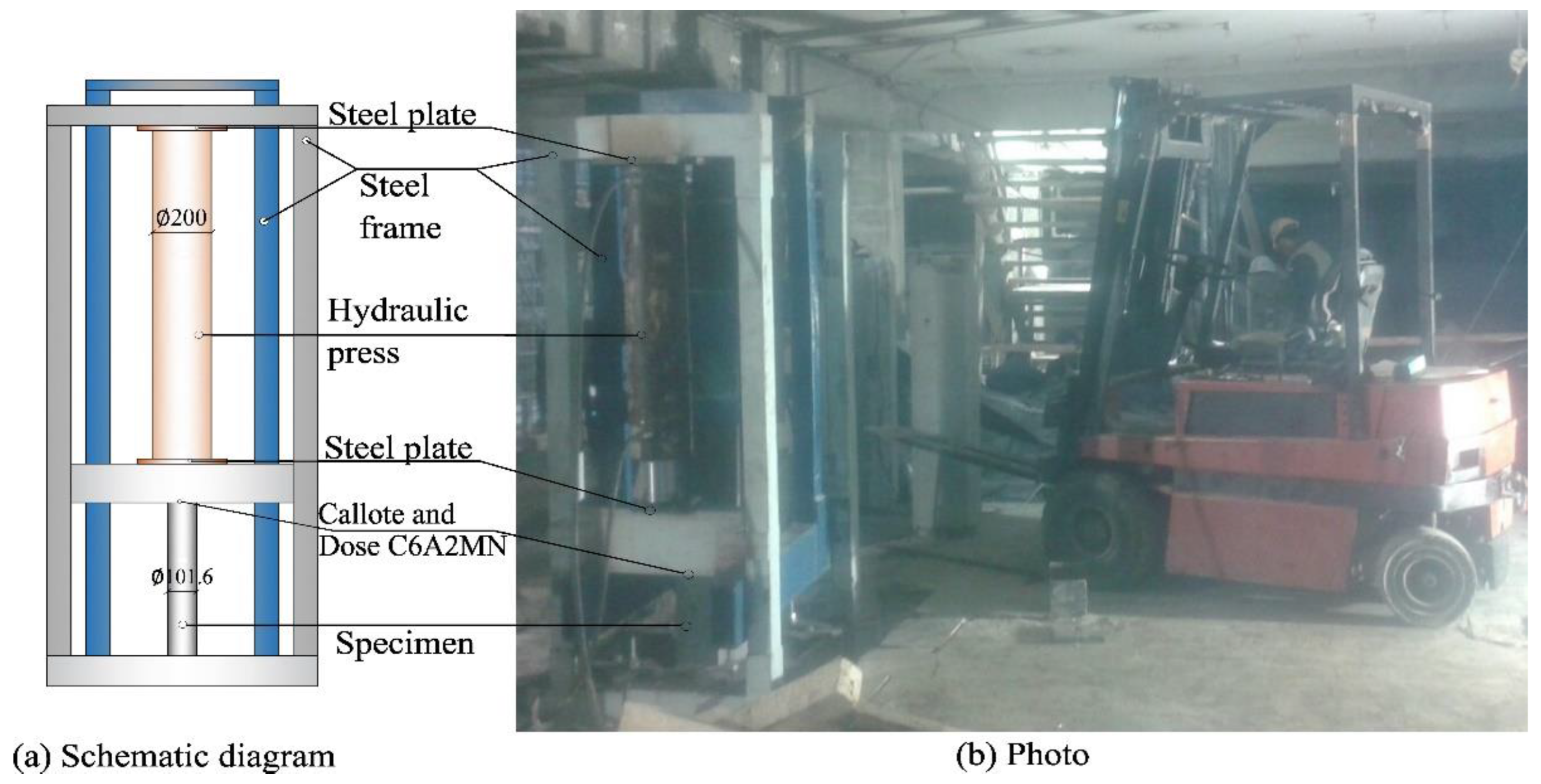
Figure 2.
Specimens after failure.

Figure 3.
CFT column 3D model and meshing.

Figure 4.
Stress–strain diagram for confined and unconfined concrete.

Figure 5.
Stress–strain diagram for steel.

Figure 6.
Specimen FEM results: (a) specimen C1; (b) specimen C2.

Figure 7.
N-ε relation obtained in tests and FEM: (a) specimen C1; (b) specimen C2.

Table 1.
Specimen details.
| Specimen | L | D | t | NTEST | NFEM | NFEM/NTEST | |
|---|---|---|---|---|---|---|---|
| - | [m] | [mm] | [mm] | - | [kN] | [kN] | [%] |
| S1 | 0.5 | 101.6 | 2.7 | 0.094 | 315.78 | 329.10 | - |
| S2 | 1.0 | 101.6 | 2.7 | 0.187 | 297.84 | 328.09 | - |
| C1 | 0.5 | 101.6 | 2.7 | 0.113 | 701.71 | 697.52 | 99.40 |
| C2 | 1.0 | 101.6 | 2.7 | 0.227 | 555.57 | 568.65 | 102.35 |
Table 2.
Material properties used in ABAQUS.
| Concrete | Steel | ||||||
|---|---|---|---|---|---|---|---|
| Unconfined | Confined | ||||||
| [MPa] | [MPa] | [MPa] | [MPa] | [-] | [MPa] | [MPa] | [-] |
| 30.5 | 32,965 | 48.5 | 36,986 | 0.2 | 355 | 210,000 | 0.3 |
Table 3.
Ultimate values of axial forces of CFT column specimen C1.
| NTEST [kN] | NTEST/ NFEM | NTEST/ NEC4 | NTEST/ NEC4, conf. | NTEST/ NACI/AS | NTEST/ NAISC | NTEST/NAIJ |
|---|---|---|---|---|---|---|
| 701.71 | 1.006 | 1.351 | 1.049 | 1.443 | 1.380 | 1.420 |
Table 4.
Ultimate values of axial forces of CFT column specimen C2.
| NTEST [kN] | NTEST/ NFEM | NTEST/ NEC4 | NTEST/ NEC4, conf. | NTEST/ NACI/AS | NTEST/ NAISC | NTEST/NAIJ |
|---|---|---|---|---|---|---|
| 555.57 | 0.977 | 1.069 | 0.946 | 1.143 | 1.093 | 1.124 |
Disclaimer/Publisher’s Note: The statements, opinions and data contained in all publications are solely those of the individual author(s) and contributor(s) and not of MDPI and/or the editor(s). MDPI and/or the editor(s) disclaim responsibility for any injury to people or property resulting from any ideas, methods, instructions or products referred to in the content. |
© 2024 by the authors. Licensee MDPI, Basel, Switzerland. This article is an open access article distributed under the terms and conditions of the Creative Commons Attribution (CC BY) license (https://creativecommons.org/licenses/by/4.0/).
Share and Cite
MDPI and ACS Style
Radovanović, M.M.L.; Nikolić, J.Z. Experimental Investigation and Numerical Analysis of the Axial Load Capacity of Circular Concrete-Filled Tubular Columns. Buildings 2024, 14, 1329. https://doi.org/10.3390/buildings14051329
AMA Style
Radovanović MML, Nikolić JZ. Experimental Investigation and Numerical Analysis of the Axial Load Capacity of Circular Concrete-Filled Tubular Columns. Buildings. 2024; 14(5):1329. https://doi.org/10.3390/buildings14051329
Chicago/Turabian StyleRadovanović, Marija M. Lazović, and Jelena Z. Nikolić. 2024. "Experimental Investigation and Numerical Analysis of the Axial Load Capacity of Circular Concrete-Filled Tubular Columns" Buildings 14, no. 5: 1329. https://doi.org/10.3390/buildings14051329
Note that from the first issue of 2016, this journal uses article numbers instead of page numbers. See further details here.