
Five-Axis Finish Milling Machining for an Inconel 718 Alloy Monolithic Blisk


1
Department of Mechanical Engineering, Cheng Shiu University, Kaohsiung 833301, Taiwan
2
Institute of Mechatronics Engineering, Cheng Shiu University, Kaohsiung 833301, Taiwan
*
Author to whom correspondence should be addressed.
Appl. Sci. 2024, 14(10), 4015; https://doi.org/10.3390/app14104015
Submission received: 29 March 2024
/
Revised: 22 April 2024
/
Accepted: 4 May 2024
/
Published: 9 May 2024
(This article belongs to the Special Issue Selected Papers from the 12th International Multi-Conference on Engineering and Technology Innovation (IMETI 2023))
Abstract
:Blisks subjected to rough machining for channel creation must undergo finishing processes, and such processes must achieve the required tolerance limits. A high-quality surface finish and predictable long tool life are critical for the finish milling of blisks. Accordingly, the aim of this study was to optimize parameters for the finish machining of an Inconel 718 alloy monolithic blisk. Ball-cone mills were used to machine the blade surface at a constant depth. A sensory tool holder was used to collect cutting force signals during machining, and a digital microscope was used to examine tool wear. The surface texture measuring instrument was used to measure blisk blade surface roughness to evaluate processing quality. This study manipulated two cutting parameters, namely cutting speed and feed per tooth, and investigated their effects. The relationship between cutting conditions and machining efficiency was analyzed. According to the experimental results, we identified a set of optimal parameters at effective cutting speeds of 46.53 m/min, feed per tooth of 0.1 mm/tooth, and depth of cut of 0.05 mm for marginal tool wear and fast cutting speeds. Then the corresponding tool life was estimated by using the derived parameters.
1. Introduction
A monolithic blisk is a critical component of an aircraft engine (aero engine). In contrast to the traditional fan design, in which multiple removable blades are assembled on an individual disk, the design of a blisk considers the blades and their holder disk as a monolithic construction. This design can reduce weight, improve stability during high-speed revolutions, and improve the performance of engines. Moreover, the design obviates the necessity of assembling the blades and the disk during the production process, which improves manufacturing efficiency. Blisks can be manufactured using various methods; the most common method involves machining from solid material by using machine tools. It must be emphasized that a blisk presents a complex geometry, so the machining costs are pretty high. It operates at high temperatures, thus blisks material must have excellent mechanical properties to ensure its high durability. The requirements for material selection, processing environment, and precision in the manufacturing process are strict. Blisks are usually made from difficult-to-cut materials such as titanium and nickel-based alloys and require the use of multiaxis machine tools and complex toolpath planning equipped with suitable tools that operate on well-chosen cutting parameters.
Inconel 718 has been used frequently as blisk material quality because of its superior mechanical properties. However, the machinability of Inconel 718 is relatively low owing to its extreme performance. This thermal-resistant alloy exhibits high strength and tends to exhibit strain hardening even at high temperatures, resulting in high cutting forces and extreme temperatures during machining. Traditional carbide tools wear quickly during machining, especially uncoated tungsten carbide inserts employed under dry conditions. Research has focused on improving the machining efficiency of Inconel 718 through the use of tool coatings, the use of coolants, and the optimization of cutting parameters [1]. Liquid coolants, also known as cutting fluids, are used to cool the tool and workpiece by removing the heat generated during machining. Pereira et al. proposed the use of external MQL lubrication (CryoMQL) with CO2 as an internal coolant for the cryogenic cooling of Inconel 718 during milling [2]. This ambient cooling method was demonstrated to engender increased tool life [3]. Kursuncu et al. conducted cryogenic heat treatment on cemented carbide tools to increase their wear resistance and thus improve their cutting performance [4].
Scholars have extensively discussed the effect of cutting conditions, including the tool material and geometry, feed rates, and radial depth of cuts, on tool life [5]. Different cutting methods with various cutting parameters and machining strategies have been proposed for controlling tool wear [6]. Moreover, a study introduced a laser preheating-assisted system and an ultrasonically assisted system for optimizing cutting parameters and improving cutting performance [7]. The computer-aided engineering (CAE) software with the commercial SOLIDWORKS® 2014 was also used to predict the deformations and stresses of the spindle and cutting tools under external loads to evaluate the rationality of cutting conditions [8,9].
The first step of blisk machining entails rough milling, followed by the establishment of a boundary contour on the free surface of the blade [10] and then the control of the tool axis and cutting path to remove the groove material [11]. Traditional flank mills or barrel cutters are often used for machining [12]. In rough machining, efficiency is essential. Studies have presented a plunge milling strategy or four-axis cycloid path for material removal to improve efficiency [13]. Although most studies on blisk machining have discussed roughing processes [14], the finishing operation is also of increased importance in order to achieve the prescribed geometrical precision and surface roughness. High-quality active cutting surfaces and predictable, long tool life are critical conditions in blisk milling. Selecting the optimal machining parameters to obtain the desired surface quality and tool life is the most critical task in blisk finishing.
The aim of the present study is to optimize parameters for the finish machining of Inconel 718 alloy monolithic blisk blades. AlTiN-coated tapered ball end mills were used to machine the surfaces of the blades at a constant depth. The study also investigated the effects of two manipulated cutting parameters: cutting speed and feed per tooth. Cutting force signals during the machining process were collected using a sensory tool holder, and tool wear was observed under a digital microscope. The relationship between cutting conditions and machining efficiency was analyzed. The study results can serve as a reference in the optimization of parameters for the finish machining of blisk blades.
2. Machining of Blisk Blades
Figure 1 depicts a computer-aided design (CAD) model and a solid model of a typical monolithic blisk. A nickel-based alloy was subjected to rough machining and grooving processes to produce the blisk; subsequently, the finishing path of the blade was planned according to the shape of the machined blisk by using the impeller module in Siemens NX 10 software, as illustrated in Figure 2. The driving method was blade finishing milling. In the multi-axis machining of NX, in order to better control the inclination angle of the tool axis, we can set the lead angle and tilt angle according to the direction of the tool path. Previous studies disclosed that when the inclination angle is 25° in machining, the workpiece will have better surface roughness [15]. After selecting the blade surface, we set the tilt angle of the tool to 0.2° and set the minimum lead angle to −30°. A negative lead angle value indicates that the tool is tilted backward relative to the tool path direction. The tool axis was automatically determined by the NX program. After the toolpath was completed, VERICUT—a virtual cutting program—was used for verification to avoid interference in the toolpath and prevent collisions. Figure 3 presents the relationship between the tool axis and the blade surface in VERICUT. The left figure shows the direction of the tool axis relative to the blisk, and the right figure shows the simulation of finishing after semi-finishing.
2.1. The Geometrical Parameters of the Blisk
2.2. Material
Inconel 718 has high strength and oxidation/corrosion resistance at elevated temperatures, rendering it suitable for high kinetic–energy and corrosion-resistant environments in the aerospace industry. Inconel 718 is primarily composed of nickel and chromium. Nickel can improve heat resistance and corrosion resistance, and chromium can improve oxidation resistance and sulfur resistance. Table 2 lists the mechanical properties of Inconel 718, which were provided by the material supplier Xitron Innovation [16].
2.3. Experimental Equipment
The milling machine was a five-axis machining center CT-630 (Tongtai, Kaohsiung, Taiwan) equipped with a Siemens 840Dsl CNC controller.
The material of a cutting tool considerably influences the machining of Inconel 718 alloy blisks. The tool must have high thermal hardness, good ductility, high wear resistance, and high impact resistance. In this study, a tapered ball-nose end mill (Jen Wu Cheng Shun Turning Tools, Kaohsiung, Taiwan) was used for machining, as displayed in Figure 5. Several studies on the machining of nickel-base alloys have shown that TiAlN-coated tools have better tool life in high-speed milling than other coatings, such as TiN and TiCN [17]. Therefore, this study used TiAlN-coated. The specifications of the tool are presented in Table 3 [18]. We used water-soluble cutting fluids during the cutting process.
A sensory tool holder (pro-micron, Kaufbeuren, Germany) was used to measure cutting force signals [19]. The sensory tool holder collected the axial cutting force, cutting torque, and X-axis and Y-axis bending moment during the finish machining of the blisk blades and wirelessly sent the collected data to a computer. The X-axis and Y-axis bending moments are defined as the bending moments in the XZ plane and YZ plane, respectively, where the Z-axis is the axial direction of the spindle. Because the tool axis was set to side milling during the cutting process, the bending moment was selected as the primary observation parameter. Polar diagrams of the bending moment in the X-Y direction were used to observe the force in real time [20]. The specifications of the sensory tool holder are presented in Table 4.
A digital microscope (VHX900F, Keyence, Osaka, Japan) with depth-of-field synthesis and multiple illumination functions was used to examine the milling cutters during the experiments. The microscope was used to examine the wear of the cutting edge and the side edge after machining. The magnification of the microscope ranges from 20× to 1000×; we set the magnification to 100× to examine the tools.
3. Finish Machining Strategy and Method
The machining strategy first involved rough machining on the blank and grooving using a torus milling cutter with a diameter of 5.0 mm and a corner radius of 0.5 mm. The thickest part of the blade was machined to a thickness of 2.18 mm. To ensure the surface quality, a ball-end mill with R2.0 was used for semi-finish machining. Processed the thickest part of the blade to 1.78 mm with the machining allowance set to 0.1 mm. Finally, the tapered ball-nose end mill was used for finishing to the required dimensions of 1.59 mm. The machining process is displayed in Figure 6. During the machining process, we set different parameters for the cutting speed and feed per tooth to observe the cutting bending moment and tool wear.
3.1. Cutting Speed
3.1.1. Processing Conditions and Parameters
It was reported that feed has no significant effect on carbide cutter milling Inconel 718 [17]. Nevertheless, cutting speed is related closely to cutting force and tool wear. An appropriate range of cutting speed for side milling has been proposed in the literature. Hence, in our experiments, the depth of cut and feed per tooth Fz were fixed, and different cutting speeds were set (ranging from 26 to 96 m/min). The effective cutting speed during the cutting process is very important. It is calculated based on the effective diameter , as shown in Figure 7 [21].
where is the ball nose diameter. φ is the inclination angle of the tool. Because the lead angle is set to −30° in the NX program, the maximum tool inclination angle is 30°. The maximum effective diameter can be calculated to be 2.115 mm. When the cutting depth is tiny, the effective cutting speed is much lower than the setting speed, and the tool cutting conditions will be lower than its application range. Therefore, this study recalculated the effective cutting speed .
Thus, eight experiments were performed. The effective cutting speeds after recalculation are listed in Table 5. Each experiment was a complete process in which a new tool was used for blade cutting. In Experiment 7, the cutting speed was originally set to 86 m/min, and the spindle speed was set to 9125 RPM, which resonated with the machine. Therefore, the cutting speed was increased to 91 m/min in this experiment. Under the fixed feed per tooth, an increase in the cutting speed also engendered an increase in feed, which reduced the time required for processing.
3.1.2. Cutting Signal Capture and Analysis
During the machining process, cutting force signals were captured by the sensory tool holder. Because the toolpath involved side milling using a side rake, the tool was mainly subjected to lateral forces. The bending moment was thus used as the basis for evaluating the cutting condition. The toolpath progressed from the periphery of the blade to the hub on a layer-by-layer basis along the blade surface, as illustrated in Figure 2. The bending moment signals captured in each experiment were recorded on the basis of the cutting layer, as shown in Figure 8. The bending moments in Experiments 1–3 and 5–6 were stable, while the value raised in Experiment 4 and continued to rise in Experiments 7 and 8. It is mentioned in the literature that cutting speed and cutting force are not linearly related [17]. At medium cutting speeds, because of the material properties of Inconel 718, the cutting force will first decrease, then increase slightly as the cutting speed changes, and become stable. But when the cutting speed exceeds the critical value, the cutting temperature will increase. The tool edge will be welded, and the front edge will be seriously worn. The cutting force will increase significantly. It can be speculated that the cutting speed in Experiment 7 exceeded the critical value, indicating that the cutting conditions were inappropriate. The abnormal increase in Experiment 4 may come from machine vibration or cutting chatter.
3.1.3. Tool Wear and Cutting Moment
The captured bending moment signals during processing in the x direction and y direction were plotted on the x- and y-axes, respectively, and a polar diagram of the bending moment signals was generated, as displayed in Figure 9. The size and distribution of the plots on the polar diagram were examined to determine the cutting force and damage to the tool holder. According to the distribution of the plots, Experiments 1–3 exhibited the most concentrated and uniform distributions, indicating that the force in the cutting process was average and stable. The graphs of Experiments 7 and 8 were relatively scattered and revealed that the number of flutes was two. The data revealed that the bending moment increased. Tool wear was observed under a digital microscope with a magnification of 100×, as depicted in Figure 10. Because of the setting of the tool axis (Figure 3), the contact area between the tool and the blade was on the side cutting edge of the front end of the tool. The most severe wear occurred on the flank of the side edge. Although the bending moment is usually the best representation of tool wear in side milling among cutting forces, it is not necessarily the cause of tool wear. The tool in Experiment 4 can be observed to have more serious wear compared to Experiments 1~3. Severe wear was demonstrated by the tool flank in Experiments 7 and 8. In the machining of difficult-to-cut materials, flank wear mainly comes from the amorphous transformation caused by friction and heat accumulation between the tool and the workpiece. It can be speculated that the temperature generated by the cutting speed under this condition is too high, which has caused welding or plastic deformation on the tool surface [22].
3.2. Feed per Tooth
3.2.1. Processing Conditions and Parameters
According to the experimental results regarding cutting speeds, we also considered tool wear and machining efficiency. Cutting speeds of 66 and 76 m/min were selected as the reference, and the feed per tooth was adjusted. The machining parameters were determined and are presented in Table 6. A new tool was used for each experiment.
3.2.2. Cutting Signal Capture and Analysis
As presented in Figure 11, Experiments 9 and 12 yielded lower bending moment curves than did the other experiments. When the feed per tooth was set to 0.05 mm, less cutting force was observed. The cutting forces at a feed per tooth of 0.1 and 0.075 mm were similar. The feed per tooth has a significant effect on the cutting force, but the relationship is not linear. In the literature, a second-order nonlinear cutting force model of spindle speed and feed per edge was derived based on experimental data [23]. In experiments, there are also situations where the specific cutting forces of 0.06 and 0.07 mm/tooth are quite close.
3.2.3. Tool Wear and Cutting Moment
According to the polar diagram of the bending moment, the distributions observed for Experiments 9 and 12 were more concentrated than those observed for the other experiments (Figure 12). The other diagrams revealed a relatively large cutting force, and the tool may break at dense points. The tool exhibited various degrees of wear under magnification, as illustrated in Figure 13. Experiments 9 and 12 yielded relatively low wear, which is consistent with the smaller bending moments we observed.
4. Tool Life Test
Through basic cutting experiments, we determined the relationship between cutting parameters, bending moments, and tool wear. The experimental results could be used to evaluate machining efficiency and surface roughness requirements. For mechanical efficiency considerations, this study expected the blade surface roughness to reach a satin finish, which means the roughness requirement is RZ6.3 (Ra1.6). We measured the finished surface roughness, as shown in Figure 14. According to the measurement results, we explored reasonable machining parameters that could be used to test the tool’s life.
4.1. Assessment of Surface Roughness
Currently, two methods are widely used in the aerospace industry to measure surface roughness: contact and noncontact. We used the noncontact method by portable surface texture measuring instrument for online measurement during processing. The instrument was HANDYSURF+35 (TOKYO SEIMITSU, Tokyo, Japan) and its resolution can reach 0.0007 μm. Each blade was measured three times to obtain the average. Non-contact 3D white light interferometer microscope Opt-scope (TOKYO SEIMITSU, Tokyo, Japan) with a high vertical resolution of 0.01 nm was used for offline measurement. We compared the results of the two measurement methods, as shown in Figure 15. The results revealed that all processing results in Experiments 1–14 fulfilled the roughness requirements.
4.2. Repetitive Experiments
The basic cutting experiments revealed optimal machining parameters yielding small and stable cutting forces, which helped improve the surface quality of the blade. However, considering processing efficiency, one can adjust the machining parameters within an acceptable surface quality to shorten the machining time. We selected the parameters of Experiment 11 and performed repeated experiments by using the same tool 12 times (Table 7) for tool life assessment.
4.3. Bending Moment and Tool Wear
The cutting force increased steadily as the experiment progressed, as shown in Figure 16. The bending moment demonstrated a step jump after Experiment 23. We assessed magnified images of the tool and detected a crack on the flank of the tool after Experiment 23 (Figure 17). The cracked part is built-up-edge (BUE) adhesion [24]. After BUE is formed and peeled off, the coating will be taken away and part of the edge will peel off. Therefore, when BUE occurs, the tool wear increases significantly, and the bending moment also increases significantly. These phenomena will cause a decrease in surface roughness and dimensional accuracy, which then often requires tool replacement. On the basis of the evaluation results, we determined that the tool life was approximately eight blades under the selected surface quality and efficiency parameters.
In addition, every time a new blade is cut, the bending moment curve first decreases and then gradually increases. This phenomenon can be speculated that when the end mill is deeper and deeper in the groove, the cutting reaction force of the blade gets bigger and bigger. Chip removal becomes more difficult, resulting in an increasing bending moment in the later stage.
5. Conclusions
In this study, we conducted basic cutting and tool life experiments to analyze cutting conditions in the blisk finishing processes. Force signals collected by a sensory tool holder directly indicated the cutting forces and the influence of machining parameters on the cutting forces was nonlinear; this could thus help us select efficient parameters. The bending moment diagram also accurately indicated tool wear, which could help us estimate the time required to change the tool. On the basis of our findings, we drew the following conclusions:
- A cutting speed between 66 and 76 m/min (effective cutting speed between 46 and 53 m/min) can provide a relatively low cutting force, which can shorten the machining time and maintain surface quality.
- A feed per tooth of 0.05 mm can provide a relatively low cutting force, and a feed per tooth of 0.075 and 0.1 mm can provide relatively high cutting forces, and the values are similar.
- A cutting speed of 66 mm/min (effective cutting speed of 46 m/min) and feed per tooth of 0.1 mm can provide the most stable cutting force and the highest processing efficiency.
- Under the aforementioned conditions, a tapered ball-nose end mill can process a total of eight blades.
Author Contributions
Conceptualization, M.-H.T. and J.-N.L.; methodology, M.-H.T.; software, T.-L.H. and D.-K.H.; validation, T.-H.C.; formal analysis, M.-H.T.; investigation, T.-H.C.; resources, J.-N.L.; data curation, D.-K.H.; writing—original draft preparation, D.-K.H.; writing—review and editing, M.-H.T.; supervision, T.-H.C.; project administration, M.-H.T.; funding acquisition, J.-N.L. All authors have read and agreed to the published version of the manuscript.
Funding
This research received no external funding.
Institutional Review Board Statement
Not applicable.
Informed Consent Statement
Not applicable.
Data Availability Statement
The authors will supply the relevant data in response to reasonable requests.
Conflicts of Interest
The authors declare no conflicts of interest.
References
- Kuo, C.P.; Su, S.C.; Chen, S.H. Tool life and surface integrity when milling Inconel 718 with coated cemented carbide tools. J. Chin. Inst. Chem. Eng. 2010, 33, 915–922. [Google Scholar] [CrossRef]
- Pereira, O.; Urbikain, G.; Rodríguez, A.; Fernández-Valdivielso, A.; Calleja, A.; Ayesta, I.; López de Lacalle, L.N. Internal cryolubrication approach for Inconel 718 milling. Procedia. Manuf. 2017, 13, 89–93. [Google Scholar] [CrossRef]
- Pereira, O.; Celayab, A.; Urbikaín, G.; Rodríguez, A.; Fernández-Valdivielso, A.; López de Lacalle, L.N. CO2 cryogenic milling of Inconel 718: Cutting forces and tool wear. J. Mater. Res. Technol. 2020, 9, 8459–8468. [Google Scholar] [CrossRef]
- Kurşuncu, B.; ÇAY, V.V. Effect of deep cryogenic treatment on cutting performance in Inconel 718 milling. In Proceedings of the International Engineering and Natural Sciences Conference (IENSC 2019), Diyarbakır, Turkey, 6–8 November 2019; pp. 948–953. [Google Scholar]
- Krain, H.R.; Sharman, A.R.C.; Ridgway, K. Optimisation of tool life and productivity when end milling Inconel 718TM. J. Mater. Process. Technol. 2007, 189, 153–161. [Google Scholar] [CrossRef]
- Szablewski, P.; Dobrowolski, T.; Chwalczuk, T. Optimization of Inconel 718 milling strategies. Mechanik 2019, 92, 824–826. [Google Scholar] [CrossRef]
- Lin, S.Y.; Yang, B.H. Experimental Study of Cutting Performance for Inconel 718 Milling by Various Assisted Machining Techniques. Solid State Phenom. 2019, 294, 129–134. [Google Scholar] [CrossRef]
- Hong, C.C.; Chang, C.L.; Ou, N.R.; Lin, C.Y. CAE Analysis of Primary Shaft Systems in Great Five-Axis Turning-Milling Complex CNC Machine. Proc. Eng. Technol. Innov. 2019, 12, 1–8. [Google Scholar]
- Hong, C.C.; Chang, C.L.; Huang, C.C.; Yang, C.C.; Lin, C.Y. CAE Analysis of Secondary Shaft Systems in Great Five-axis Turning-Milling Complex CNC Machine. Adv. Technol. Innov. 2017, 3, 43–50. [Google Scholar]
- Hu, C.G.; Zhang, D.H.; Ren, J.X.; Yang, L. Research on the 5-axis Machining of Blisk. Mater. Sci. Forum 2006, 532–533, 612–615. [Google Scholar] [CrossRef]
- Huang, J.C.; Liu, X.L.; Yue, C.X.; Cheng, Y.N.; Zhang, H. Tool Path Planning of 5-Axis Finishing Milling Machining for Closed Blisk. Mater. Sci. Forum 2012, 723, 153–158. [Google Scholar] [CrossRef]
- Lu, Y.A.; Ding, Y.; Wang, C.Y.; Zhu, L.M. Tool path generation for five-axis machining of blisks with barrel cutters. Int. J. Prod. Res. 2019, 57, 1300–1314. [Google Scholar] [CrossRef]
- Luo, M.; Hah, C.; Hafeez, H.M. Four-axis trochoidal toolpath planning for rough milling of aero-engine blisks. Chin. J. Aeronaut. 2019, 32, 2009–2016. [Google Scholar] [CrossRef]
- Chen, T.H.; Lee, J.N.; Tsai, M.H.; Shie, M.J.; Lin, C.Y. Optimization of milling parameters based on five-axis machining for centrifugal impeller with titanium alloy. J. Phys. Conf. Ser. 2022, 2345, 012019. [Google Scholar] [CrossRef]
- Liao, Y.S.; Lin, H.M.; Wang, J.H. Behaviors of end milling Inconel 718 superalloy by cemented carbide tools. J. Mater. Process. Technol. 2008, 201, 460–465. [Google Scholar] [CrossRef]
- Xitron Innovation Co., Ltd. Available online: https://www.ixitron.com/ (accessed on 1 October 2022).
- Sharman, A.; Dewes, R.C.; Aspinwall, D.K. Tool life when high speed ball nose end milling Inconel 718. J. Achiev. Mater. 2001, 118, 29–35. [Google Scholar] [CrossRef]
- Jen Wu Cheng Shun Turning Tool Co., Ltd. Available online: http://www.jsk-tools.com.tw/ (accessed on 1 October 2022).
- Lu, Z.; Wang, M.; Dai, W. Machined surface quality monitoring using a wireless sensory tool holder in the machining process. Sensors 2019, 19, 1847. [Google Scholar] [CrossRef]
- Tsai, M.H.; Lee, J.N.; Shie, M.J.; Deng, M.H. Intelligent Performance Prediction of Flank Milling of Ti6Al4V Using Sensory Tool Holder. Sens. Mater. 2022, 34, 3241–3253. [Google Scholar] [CrossRef]
- Daymi, A.; Boujelbene, M.; Linares, J.M.; Bayraktar, E.; Amara, A. Influence of workpiece inclination angle on the surface roughness in ball end milling of the titanium alloy Ti-6Al-4V. J. Achiev. Mater. Manuf. Eng. 2009, 35, 79–86. [Google Scholar]
- Li, C.; Hu, Y.; Zhang, F.; Geng, Y.; Meng, B. Molecular dynamics simulation of laser assisted grinding of GaN crystals. Int. J. Mech. Sci. 2023, 239, 107856. [Google Scholar] [CrossRef]
- Tsai, J.C.; Kuo, C.Y.; Liu, Z.P.; Hsiao, K.H.H. An investigation on the cutting force of milling Inconel 718. MATEC Web Conf. 2018, 169, 01039. [Google Scholar] [CrossRef]
- Özbek, O. Evaluation of Nano Fluids with Minimum Quantity Lubrication in Turning of Ni-Base Superalloy UDIMET 720. Lubricants 2023, 11, 159. [Google Scholar] [CrossRef]
Figure 1.
CAD model and solid model of monolithic blisk.

Figure 2.
Blade finishing tool path on NX. (The depth of cut has been adjusted to display the tool path clearly. The dark blue dotted lines are the engage and retract of the tool path).
Figure 2.
Blade finishing tool path on NX. (The depth of cut has been adjusted to display the tool path clearly. The dark blue dotted lines are the engage and retract of the tool path).

Figure 3.
Tool axis in VERICUT. (Each blade used a separate tool path, so the colors are different).
Figure 3.
Tool axis in VERICUT. (Each blade used a separate tool path, so the colors are different).

Figure 4.
Dimensions of monolithic blisk (unit: mm).

Figure 5.
Tapered ball nose end mill.
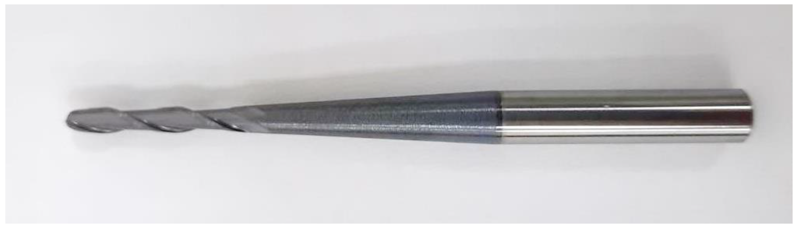
Figure 6.
The machining process: (a) Blank, (b) Roughing, (c) Semi-Finishing, (d) Finishing.
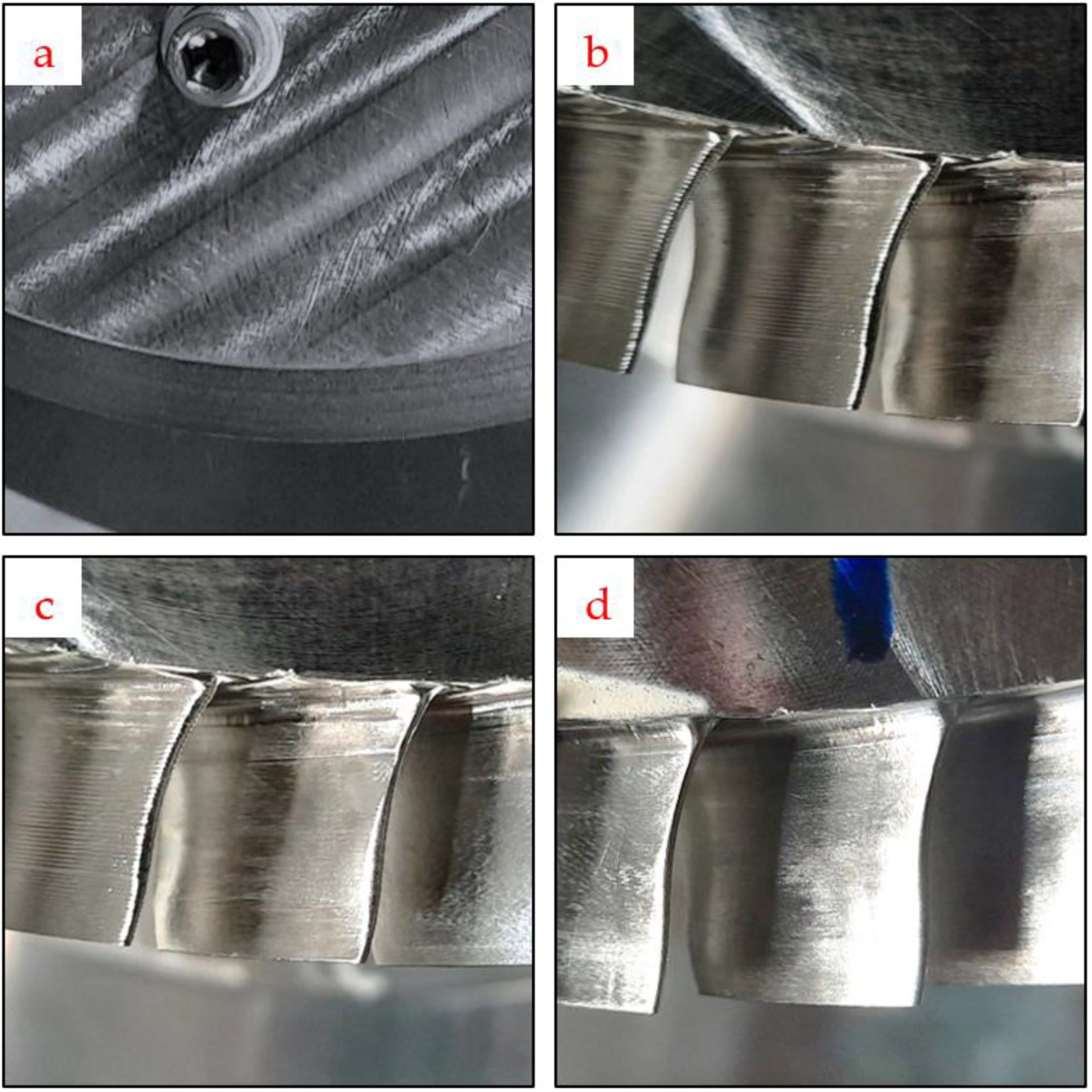
Figure 7.
The effective cutting speed for inclined milling.

Figure 8.
Bending moments at different cutting speeds.

Figure 9.
Bending moment in polar coordinates at different cutting speeds.

Figure 10.
Flank wear at different cutting speeds.
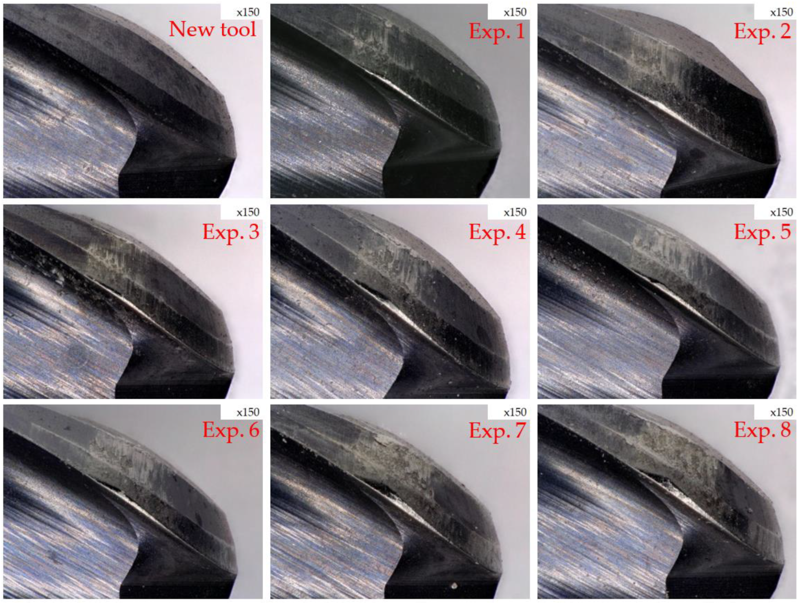
Figure 11.
Bending moments at different feeds per tooth.

Figure 12.
Polar coordinates of bending moment at different feeds per tooth.

Figure 13.
Flank wear at different feeds per tooth.

Figure 14.
Finished blade surface.

Figure 15.
Surface roughness measurement results.

Figure 16.
Bending moments in repeated experiments.

Figure 17.
Flank wear after Experiments 22 (Left) and 23 (Right). (The red circle shows the cracked part).
Figure 17.
Flank wear after Experiments 22 (Left) and 23 (Right). (The red circle shows the cracked part).


Table 1.
Blisk geometry.
| Property | Values |
|---|---|
| Outer diameter of the blisk (mm) | 364 |
| Outer diameter of the hub (mm) | 331.5 |
| Length of the blade (mm) | 16.25 |
| Thinnest part of the blade (mm) | 0.23 |
| Thickest part of the blade (mm) | 1.59 |
| Groove width (mm) | 6.46 |
| Number of blades | 78 |
Table 2.
Mechanical properties of Inconel 718.
| Property | Values |
|---|---|
| Density (g/cm3) | 8.19 |
| Poisson’s ratio | 0.29 |
| Young’s modulus (GPa) | 200 |
| Ultimate stress (MPa) | 860 |
| Yield stress (MPa) | 551 |
| Elongation (%) | 51.7 |
| Hardness (HRB) | 97.7 |
| Thermal conductivity (W/m·K) | 11.2 |
Table 3.
Specification of tapered ball nose end mill.
| Property/Composition | Values |
|---|---|
| Shank diameter (mm) | 6 |
| Tool nose radius (mm) | 1.5 |
| Over length (mm) | 75 |
| Cutting length (mm) | 20 |
| Taper angel (degree) | 3 |
| Rake angle (degree) | 2 |
| Flute helix angle (degree) | 30 |
| Flutes | 2 |
| Material | Tungsten Carbide |
| Coating | AlTiN |
Table 4.
Specification of sensory tool holder.
| Property | Values |
|---|---|
| Measuring frequency (Hz) | 2500 |
| Maximum allowable speed (rpm) | 18,000 |
| Operating temperature (°C) | 0–50 |
| Collet size | ER20 |
| Spindle taper | BBT-40 |
| Total length (mm) | 155 |
Table 5.
Machining parameters I.
| Cutting Speed (m/min) | Effective Cutting Speed (m/min) | Feed per Tooth Fz (mm/tooth) | Depth of Cut (mm) | Time (min/s) | |
|---|---|---|---|---|---|
| Exp. 1 | 26 | 18.33 | 0.05 | 0.05 | 56:25 |
| Exp. 2 | 36 | 25.38 | 0.05 | 0.05 | 40:53 |
| Exp. 3 | 46 | 32.43 | 0.05 | 0.05 | 32:08 |
| Exp. 4 | 56 | 39.48 | 0.05 | 0.05 | 26:26 |
| Exp. 5 | 66 | 46.53 | 0.05 | 0.05 | 22:30 |
| Exp. 6 | 76 | 53.59 | 0.05 | 0.05 | 19:43 |
| Exp. 7 | 91 | 64.16 | 0.05 | 0.05 | 16:48 |
| Exp. 8 | 96 | 67.69 | 0.05 | 0.05 | 16:06 |
Table 6.
Machining parameters II.
| Cutting Speed Vc (m/min) | Effective Cutting Speed Ve (m/min) | Feed per Tooth Fz (mm/tooth) | Depth of Cut Ap (mm) | Time (min/s) | |
|---|---|---|---|---|---|
| Exp. 9 | 66 | 46.53 | 0.05 | 0.05 | 22:30 |
| Exp. 10 | 66 | 46.53 | 0.075 | 0.05 | 16:36 |
| Exp. 11 | 66 | 46.53 | 0.1 | 0.05 | 13:02 |
| Exp. 12 | 76 | 53.59 | 0.05 | 0.05 | 19:43 |
| Exp. 13 | 76 | 53.59 | 0.075 | 0.05 | 14:09 |
| Exp. 14 | 76 | 53.59 | 0.1 | 0.05 | 12:14 |
Table 7.
Machining parameters III.
| Cutting Speed Vc (m/min) | Effective Cutting Speed Ve (m/min) | Feed per Tooth Fz (mm/tooth) | Depth of Cut Ap (mm) | Time (min/s) | |
|---|---|---|---|---|---|
| Exp. 15~26 | 66 | 46.53 | 0.1 | 0.05 | 13:02 |
Disclaimer/Publisher’s Note: The statements, opinions and data contained in all publications are solely those of the individual author(s) and contributor(s) and not of MDPI and/or the editor(s). MDPI and/or the editor(s) disclaim responsibility for any injury to people or property resulting from any ideas, methods, instructions or products referred to in the content. |
© 2024 by the authors. Licensee MDPI, Basel, Switzerland. This article is an open access article distributed under the terms and conditions of the Creative Commons Attribution (CC BY) license (https://creativecommons.org/licenses/by/4.0/).
Share and Cite
MDPI and ACS Style
Tsai, M.-H.; Chen, T.-H.; Lee, J.-N.; Hsu, T.-L.; Huang, D.-K. Five-Axis Finish Milling Machining for an Inconel 718 Alloy Monolithic Blisk. Appl. Sci. 2024, 14, 4015. https://doi.org/10.3390/app14104015
AMA Style
Tsai M-H, Chen T-H, Lee J-N, Hsu T-L, Huang D-K. Five-Axis Finish Milling Machining for an Inconel 718 Alloy Monolithic Blisk. Applied Sciences. 2024; 14(10):4015. https://doi.org/10.3390/app14104015
Chicago/Turabian StyleTsai, Ming-Hsu, Teng-Hui Chen, Jeng-Nan Lee, Tai-Lin Hsu, and Dong-Ke Huang. 2024. "Five-Axis Finish Milling Machining for an Inconel 718 Alloy Monolithic Blisk" Applied Sciences 14, no. 10: 4015. https://doi.org/10.3390/app14104015
Note that from the first issue of 2016, this journal uses article numbers instead of page numbers. See further details here.