

Simulation and Optimization of a Pendulum-Lever-Type Hole-Seeding Device
by
Hengshan Zhou
1,2,
Fei Dai
1,2,*, 
Ruijie Shi
2,
Cai Zhao
1,
Huan Deng
2,
Haifu Pan
2 and
Qinxue Zhao
2 1
State Key Laboratory of Aridland Crop Science, Gansu Agricultural University, Lanzhou 730070, China
2
College of Mechanical and Electrical Engineering, Gansu Agricultural University, Lanzhou 730070, China
*
Author to whom correspondence should be addressed.
Agriculture 2024, 14(5), 750; https://doi.org/10.3390/agriculture14050750
Submission received: 18 April 2024
/
Revised: 6 May 2024
/
Accepted: 9 May 2024
/
Published: 11 May 2024
(This article belongs to the Special Issue Precision Planting Technology and Equipment in Advanced Crop Cultivation)
Abstract
:The process of hole seeding on the mulch during full-film double-row furrow corn planting faces issues such as poor seed discharge and seed blockage. To address these challenges, a pendulum-lever-type hole-forming mechanism is designed, along with an adjustment device. By analyzing the working principles of the pendulum-lever-type hole seeder and the adjustment device, the structural parameters of the device are determined. Through theoretical analysis and simulation experiments, three-dimensional models of seeds and hole seeders are constructed. Based on MBD-DEM cosimulation, the trajectory of seed movement and the seeding process of the hole seeder are analyzed to elucidate the effects of the hole-former opening and the number of pendulum bearings on seeding quality. To improve the operational performance of the hole seeder, experiments are conducted using the hole seeder’s rotating disc speed, lever angle of the hole-former, and the number of pendulum bearings as experimental factors, with the qualification index, miss-seeding index, and reseeding index as experimental indicators. A three-factor, three-level Box–Behnken central composite experiment is performed to obtain mathematical models of the relationships between the experimental factors and indicators. Using Design-Expert 12 software, the regression models are optimized for multiple objectives to obtain the optimal parameter combination: a seeder disc speed of 49 r/min (corresponding to a forward speed of 5.76 km/h), a lever angle of 131°, and four pendulum bearings. Under this optimal parameter combination, the qualification index is 91.70%, the miss-seeding index is 4.57%, and the reseeding index is 3.73%. Experimental validation of the seeding performance of the hole seeder under the optimal parameter combination is conducted. Bench tests show that the qualification index, miss-seeding index, and reseeding index are 90.53%, 5.60%, and 3.87%, respectively. Field tests demonstrate a qualification index of 89.13%, a miss-seeding index of 5.46%, and a reseeding index of 6.41%. The actual results are consistent with the optimized values, providing valuable insights for the design and performance optimization of hole seeders.
1. Introduction
In response to the prevalent “nine droughts in ten years” phenomenon in Northwest China’s arid regions, the widespread adoption of the whole-film mulching and double-ridge furrow-sowing drought-resistant tillage technology is currently underway. This approach combines a unique ridge structure with film mulching furrow sowing, offering benefits such as water retention, soil moisture conservation, and temperature elevation [1,2]. This planting method has been widely adopted in the cultivation of crops such as corn and potatoes [3]. Production practice has demonstrated that the whole-film mulching and double-ridge furrow seeding technique increases crop yields by nearly 30% compared to conventional mulch cultivation [4]. Precision seeding on film is vital for achieving mechanized operations throughout the entire process of full-film double-ridge field crop production [3]. Film hole-seeding involves creating planting holes in the film at specific row and hole spacings, effectively minimizing damage to the film caused by seeding machinery, safeguarding the water and thermal systems of the double ridges covered by the film [5], enhancing rainwater collection and moisture retention, boosting seeding efficiency, and reducing labor and resource requirements [6]. Hence, enhancing the operational performance of hole seeders holds significant importance in advancing the mechanization of maize production in full-film double-ridge fields and promoting the evolution of precision seeding technology and equipment [7].
With the advancement of precision seeding technology, high-speed field operations have become the pivotal benchmark for evaluating seeder performance [8,9]. Gao et al. [10,11] explored the influence of particle count and cleaning element angle on seeding performance during high-speed seeding processes. Dong et al. [12] and Ma et al. [13] investigated maize seeding postures and proposed methods for adjusting seed guidance trajectories and filling postures to enhance the high-speed operation performance of seed-metering devices. However, these studies overlooked the impact of the hole-forming device on seeding effectiveness. Accelerating hole-seeder operation speeds leads to shortened seeding times, potentially resulting in hole seeders failing to smoothly dispense seeds or seeds not being dispensed promptly, causing seed blockages and damage. Research on the effect of hole-forming mechanisms on seeding outcomes during hole-seeder operations remains limited. While optimized duckbill hole-forming devices, as proposed by Wang [14], reduce soil plug formation, the incomplete opening of the soft soil pressure plate may impede seed dispersion. Gu et al. [15] suggested a robust opening method using levers and limit blocks to improve seeding success rates, but excessive duckbill opening could increase the damage caused to plastic film and the soil.
Addressing these issues, a pendulum-lever-type hole-seeding device was designed to enhance the operational performance of the seeder and promote the development of precision seeding technology. This study focused on widely used mechanical hole seeders, analyzing the seeding principles of hole-seeder hole-forming components, investigating hole-seeder bench test adjustment requirements, and optimizing structural parameters. Through cosimulation analysis using discrete element software EDEM 2020 [16] and multibody dynamics software RecurDyn V9R4 [17], joint simulations were conducted to identify optimal parameter combinations for hole seeders and key components of the hole-forming mechanism. Bench tests and field tests were conducted to validate the performance improvements.
2. Materials and Methods
2.1. Machine Structure and Working Principle
2.1.1. Machine Structure
The pendulum plate and lever hole-seeding device was mainly composed of a fixed plate, movable shaft, electric actuator, rotating disc, connecting bracket, fixed disc cover, pendulum plate, and hole-former, and its structure is shown in Figure 1.
The fixed plate and connecting bracket were coaxially mounted on the movable shaft with the hole seeder’s rotating disc, fixed disc, and fixed disc cover; the hole-former was circumferentially distributed on the movable plate; the seed-discharging wheel dial was coaxially mounted with the seed-discharging wheel; the pendulum mechanism hinged to the lower portion of the fixed disc was adjacent to the limit lever; and the return tension spring was connected to the pendulum plate at one end and was hooked up to the fixed disc at the other end.
2.1.2. Working Principle
When the pendulum paddle hole-seeding device operates, according to the preset sowing depth and the size of the hole-seeding device, the length of the electric push rod is adjusted to change the installation height of the hole-seeding device (the vertical distance between the center of the hole-seeding device axis and the seedbed belt). The adjustment range of the electric push rod was 305~505 mm, and the installation height of the hole-seeding device ranged from 180~471 mm, to meet the agronomic technical requirements of different sowing depths. The adjusting trajectory is shown as a red line in Figure 2a.
Within the hole-seeding chamber, the corn seed population flows dynamically under the influence of friction and gravity in the seed holding area of the hole seeder’s fixed disk chamber. Seeds in the seed holding area rely on gravity and interseed force to enter the holes of the seed discharge wheel. The rotating sleeve contacts the dial of the seed discharge wheel, driving the rotation of both the seed discharge wheel and the seed brush wheel. The brush wheel rotates counterclockwise to clear any seeds that have not fully entered the holes. As the seed discharge wheel rotates to a specific position, seeds fall into the cavity of the hole-forming device under the combined influence of gravity and the seed-clearing plate. At this point, the lever slides around the outer circle of the pendulum plate bearing, while the bearing group acts on the upper end of the lever to keep the movable hole-former open. The seeds then fall into the soil, completing one sowing cycle, as illustrated in Figure 2b.
2.2. Design of Key Components for Hole-Seeding Devices
The hole-seeding device plays a crucial role in the film-sowing process and is primarily composed of the hole-former unit and the swinging disk mechanism. The size and timing of the hole-former’s opening are critical factors influencing both the seeding performance of the hole seeder and the moisture retention effect of the full-film hole seeder. Excessive opening size or prolonged opening time may result in film tearing or picking, leading to noticeable soil disturbance around the holes, disrupting the ridge structure of the full-film double-row furrows and reducing soil temperature and water transfer capacity [18]. Therefore, it is essential to minimize the degree of film damage and soil disturbance caused by the hole-former while ensuring smooth seeding, thereby preserving the hydrothermal effect of the full-film double-row production system [19,20].
2.2.1. Design of the Hole-Forming Mechanism
The hole-former shape is mainly conical- and wedge-shaped, and research shows that cone-shaped hole-formers are more effective than wedge-shaped hole-formers in terms of hole formation and soil movement [21]. The structure of the conical hole-forming group, which is mainly composed of a fixed hole-former, base fixed plate, rotating sleeve, lever, return spring, and movable hole-former, is shown in Figure 3.
As shown in Figure 3b, to ensure that the seed drop is smooth and the hole-former works without clogging and film hanging, the hole-former opening degree d satisfies [22]
where d is the hole-former opening, mm; dmax is the maximum geometric size of the seed, mm.
To ensure that the seed discharge wheel-type holes are filled with single grains of seeds, the larger Jinsui No. 4 corn seeds were selected [23]. Then, the range of values of hole-former openings d was determined as 15~18.75 mm.
The length of the hole-forming mechanism affects not only the sowing depth but also the effect of the tip scraping when the soil comes out. If the length of the hole-forming mechanism is too short, it is difficult to break the film into holes; if the length of the hole-forming mechanism is too long, it is easy to hang the film, destroying the shape of the film holes, affecting corn seedling emergence. The calculation formula for the length of the dynamic into the hole device is
where d3 is the length of the movable hole-former, mm; T is the sowing depth. According to the requirements of full-film double-ridge furrow agronomic technology [2], we took 50 mm; ε is the angle between the hole-forming edge line of the fixed hole-former and the line connecting the bottom and the center of the drum, °.
Referring to the literature [24], ε = 30°, which was brought into Equation (5) to obtain d3 = 57.74 mm. After the hole-former opening was determined, the movable hole-former angle φ was determined from the geometrical relationship:
where φ is the angle of rotation of the dynamic hole-forming apparatus, °.
From this, the rotational angle φ of the movable hole-former was determined to be 14.93°~18.68°. The long arm of lever d2 is the distance from the hole-forming part to the pendulum mechanism, which is 100 mm; to ensure the stability of the opening of the dynamic hole-forming mechanism, the value of the short arm of lever d1 should be larger than the radius of the pendulum bearings by 15 mm and smaller than the distance between the centers of the two adjacent bearings by 30 mm, which was taken as d1 = 22 mm.
2.2.2. Design of Pendulum Mechanism
The pendulum mechanism comprises the pendulum plate, pendulum bearing, return tension spring, and limit lever, as depicted in Figure 4. During operation, the return tension spring keeps the pendulum disk mechanism close to the fixed disk limit lever. The lever slides along the outer circle of the pendulum disk bearing, ensuring the hole-forming mechanism remains open for seed deposition into the soil. Furthermore, the limiting device on the pendulum disk regulates the opening and closing of the hole-forming mechanism within an appropriate timeframe, facilitating smooth seeding.
In the pendulum device with reverse rotation protection, as the rotating disc moves backward, the lever glides along the outer perimeter of the bearing, prompting the pendulum disk mechanism to rotate around the pendulum pin in the same direction. Throughout this process, the movable hole-former maintains a tight closure against the fixed hole-former. Upon the lever’s disengagement from the outer circle of the bearing, the pendulum disk mechanism reverts to its initial position due to the action of the return spring, as illustrated in Figure 5.
2.3. Design of the Adjustment Mechanism and Test Bench
2.3.1. Design of Adjustment Device
The adjustment device serves the purpose of controlling and regulating sowing depth and is adaptable for altering the bench height to accommodate different sizes of hole-seeder seeding tests. Comprising the bracket, bearing seat, electric actuator, and switch controller, as depicted in Figure 6, the adjustment device is an integral component of the pendulum-lever-type hole-seeding apparatus. During operation, in accordance with various test conditions and hole-seeder dimensions, the electric actuator’s stroke is controlled to adjust the hole seeder’s height position. Concurrently, the fixed plate rotates along the axis of the movable shaft, providing support and fixation for the hole seeder.
Figure 6a shows a sketch of the four-bar mechanism of the mounting bracket, constructing the coordinate system XOY, the X-axis over point A, and the Y-axis over point B. According to the analytical method [25], the trajectory of the movement of point D on the connecting rod can be adjusted to the hole-seeding center-axis trajectory D(x,y):
where (xD, yD) are the coordinates of point D, mm; l is the initial length of the motorized actuator, mm; l0 is the electric actuator adjustment stroke, mm; l1 is the length between the bracket fixing points, mm; l2 is the crank length, mm; l3 is the length of connecting rod, mm; α0 is the angle between the line connecting points A and B and the direction of X axis; α is the crank rotation angle, °; δ is the angle between connecting rod AB and CD, °; l4 is the rocker length, mm; β is the angle between AB and BC, °.
The electric actuator stroke l0 ranges from 0 to 200 mm, i.e., the length of l2 varies from 305 to 505 mm. Considering the size of the hole-forming mechanism and the radius of the hole-seeding device [26], l4 = 400 mm, l1 = 320 mm, l3 = 100 mm, and α0 = 60°.
When the minimum adjustment stroke l0 = 0 mm, the crank angle α = 7 °, calculated using formulas (1) and (2) in the coordinate system XOY D, with point coordinates for (328, 279); we adjusted the l0 maximum to 200 mm, when the crank angle α = 43.2 °, for D point coordinates for (213, 570). The hole-seeding installation height h and point D longitudinal coordinate relationship formula is
where h is the vertical distance between the axis of hole seeding to the seedbed belt, mm; H is the vertical distance between the bracket and motorized actuator connecting the axis to the seedbed belt, mm.
When H = 750 mm, the variation range of hole-seeding installation height h is 180~471 mm, which is in line with the range of the hole-seeding radius. The axial trajectory of the hole-seeding installation position is shown as a red line in Figure 6b.
2.3.2. Structure of the Test Bench
We used this regulating device in a test stand; the structure of the test bench mainly included a bench, conveyor belt, drive roller, and roller, as shown in Figure 7.
The transmission system of the seeding test bench of the hole-seeding device is shown in Figure 8, and the direction of the arrow is the direction of power transmission. The driving motor of the hole seeder is transmitted to the gearbox through a universal transmission shaft. After the gearbox changes direction, it is first transmitted to the movable shaft by belt transmission, and then transmitted to the hole seeder through the coaxial sprocket two-stage transmission. In the same way, the conveyor belt drive motor is transmitted to the conveyor belt drive roller by chain transmission after variable speed commutation of the gearbox.
3. Seeding Process Simulation
3.1. Discrete Elemental Modeling of Corn Kernels
We randomly selected 500 seeds of Jinsui No. 4. Considering the influence of kernel shape on the seed-casting process, the kernels were categorized into flat and round according to the shape contour for counting, and the three-axis dimensions of the maize kernels were determined using digital vernier calipers, which were the length (L), width (W), and thickness (T) of the corn kernels (Figure 9).
The calculated triaxial geometric mean diameters of the seeds are shown in Table 1. Based on the three-axis geometric mean diameter and shape profile of the corn kernels, 3D modeling software was used to establish a 3D model of the kernel, and the model was imported into EDEM software in .stl format. To more accurately fit the motion of the corn kernels, spheres with unequal diameters were used to fill the kernel. We reduced the number of spherical particles required to fill a single grain to save simulation time, and we established 13 and 14 large-spherical corn grain models, as shown in Figure 10.
3.2. Modeling of Hole-Seeding Applicator Rows
While ensuring successful sowing with the hole seeder, the 3D model created using SolidWorks 2022 software was simplified to reduce the computational complexity of the simulations. The simplified model was then imported into multibody dynamics simulation software RecurDyn in .x_t format to add constraints, forces, and contact relationships for simulating the trajectory of the hole seeder during seeding. The multibody dynamics model in RecurDyn was imported into EDEM for further analysis using a wall intermediate format file. Simulation tests of the hole-seeding process were conducted based on MBD-DEM. The necessary material and contact parameters for the simulation model in the seed discharge process were obtained by reviewing the literature, as shown in Table 2 and Table 3 [27,28].
After establishing a simplified model for hole-seeding simulation [29], the simulation parameters were set to generate a total of 1000 corn grains, with each type generated at a rate of 300 grains/s, as depicted in Figure 11a. The simulation time was set to 2 min, with a time step of 2.58 × 10⁻⁵ s. To observe in detail how the seed model underwent the processes of filling, carrying, and casting during hole-seeding discharge by the hole seeder, kernels with entry hole movement within the corn grain group were selected as the observation objects. The hole-seeding model was set to be displayed in the form of filled objects with an opacity of 0.1, and its trajectory is depicted in Figure 11b. Upon completion of the simulation, Figure 12 illustrates the seedbed with falling seeds.
3.3. Single-Factor Simulation Test
To determine the range of model operating parameters, single-factor simulation experiments were necessary. Based on the operating principles of the device and relevant operational parameters of the seeder, we separately determined the experimental value range of the seeder’s dynamic disc speed, the dynamic forming plate lever angle, and the number of pendulum plate bearings.
3.3.1. Determination of Rotating Speed of Rotating Disc
The seed discharger is the core component of the hole seeder, and its seed supply speed directly determines the rotational speed of the hole seeding. To improve the operation speed of hole seeding, considering the actual seed supply speed of this mechanical seeder, the maximum speed of the hole seeder’s rotating disc was set at 80 r/min, which means that the forward speed of the hole seeding was 9.40 km/h. To adapt to different operating conditions of the seeder, we verified the sowing performance at different speeds. Selecting a low speed of 40 r/min, a medium speed of 60 r/min, and a high speed of 80 r/min, the forward speeds of the seeder were 4.72 km/h, 7.06 km/h, and 9.40 km/h, respectively.
3.3.2. Determination of the Angle of the Lever
The angle of the movable hole-former lever primarily affects the size of the hole-former opening, which varies with the lever angle. During operation, Figure 13a,b illustrate that when the lever angle of the hole-forming mechanism is 110°, the opening of the movable hole-former is small, increasing the likelihood of ‘stuck seeds’ if seeds are not promptly dispensed, leading to seed damage and affecting subsequent seeding strokes. Additionally, when the hole-forming mechanism is used for mulch-hole seeding, a small lever angle narrows the opening of the movable hole-former, preventing seeds from falling into the soil promptly, resulting in decreased seeding quality and an increased empty hole rate. In Figure 13d, when the hole-former lever is at 150°, the turning angle of the movable hole-former λ is 22.72°, elevating the risk of film tearing and soil disturbance. Conversely, in Figure 13c, when the lever is at 140°, the turning angle λ = 18.71°, nearing the maximum range value of 18.69°. Considering these factors, the optimal range for the movable hole-former lever angle was determined to be 110° to 140°.
3.3.3. Determination of the Number of Pendulum Bearings
The pendulum mechanism serves as the primary opening mechanism of the hole-former, ensuring that it operates within a reasonable timeframe. The number of pendulum bearings is a critical component for controlling the opening and closing times of the hole-forming device. If the number of pendulum bearings is insufficient, it may shorten the opening time of the moving hole-forming device, leading to issues such as seed jamming and the delayed discharge of corn kernels, which can significantly impact the effectiveness of sowing. Conversely, an excessive number of pendulum bearings extends the opening time of hole seeding but increases the risks of film tearing and the disruption of the structure of the whole-film mulching and double-ridge furrow, resulting in lower ground temperature around the seed holes and reduced moisture transfer capability. We calculated the seed drop time to satisfy the following conditions:
where is the angle between the drop point of the discharge wheel of the hole seeder and the line connecting the center and the vertical centerline of the hole seeder, (°); is the time for the hole seeding to turn over, s; ω is the hole-forming apparatus’s angular velocity, rad.
Considering the seed dispenser had a of 36° and speeds of 40 r/min, 60 r/min, and 80 r/min, the duration of hole seeding was 0.15 s, 0.1 s, and 0.075 s, respectively. When the speed of the hole seeding was increased from 40 to 80 r/min, the theoretical pulsation period of the seeding time reduced from 0.15 to 0.075 s.
Through simulation testing, we obtained the actual seed drop time of the hole seeder. We set the EDEM data-saving interval to 0.01 s and exported speed data for a single seed to create a two-dimensional line graph, as depicted in Figure 14. We analyzed the seed drop time and speed change graph for different dynamic disc speeds, and we determined the optimal number of pendulum bearings to install. We adjusted the opening and closing time of the hole-former and optimized the seed drop effect of the hole seeder.
In the seed movement process, the seed falls into the hole first, the two hole positions are rotated with the seeding wheel, and then the seed contacts the hole-forming device freely, colliding in the cavity of the hole-forming device, and finally reaching the bottom of the hole-forming device. Then, the hole-forming device opens and the seed falls to the seedbed belt. It can be seen from the Figure 14 that when the rotating speed of the hole seeder was 40 r/min, 60 r/min, and 80 r/min, the corn seeds fell freely from the seeding. The time required for this process was 0.12 s, 0.11 s, and 0.14 s, respectively. When the rotating speed of the moving disc was 80 r/min, the seed dropping time did not decrease but increased, because the rotating speed of the moving disc was too fast, and the seed was dragged by the hole-forming device, resulting in delayed falling. The maximum speed of the seeds was more than 4 m/s, and there was an obvious bounce phenomenon that occurred when the seed contacting the seedbed. Figure 15 is the change diagram of the seeding index Y of the hole seeder at different speeds when the number of pendulum bearings ranged from one to six.
where Y is the seeding index, %; M is the theoretical number of seeding holes; m is the actual number of seeding holes.
It can be seen from the Figure 15 that the number of pendulum bearings was one, the seeding index under different speeds was less than 80%. This is attributed to the brief opening duration of the hole-forming device with a single bearing. When seeds do not reach the bottom of the hole-forming device, the movable hole-former completes its cycle prematurely, resulting in fewer seeding holes. However, the seeding index was 71.94% at 40 r/min. The main reason was that the seeding period of the hole seeder was longer at a slower rotating speed, which prolonged the opening and closing time of the hole-forming device and the falling time, and the seeds could pass through before the closing of the hole-forming device. When the number of bearings was three or less, the seeding index of the hole seeder at different speeds increased significantly. When the number of bearings was more than three, the seeding index at the speed of 40 r/min tended to be stable. The seeding index at the speed of 60 r/min and 80 r/min increased by 4.82% and 5.94%, respectively, and then the seeding index fluctuated within a range of 3%. When the number of bearings was six, the seeding index did not change significantly. From our analysis, the optimal value range of the pendulum plate bearing was found to be between three and five.
3.4. Box–Behnken Experimental Design
To optimize the parameters of the hole-seeding device’s oscillating disc mechanism, an experiment was conducted using a Box–Behnken central combination experimental design to determine the optimal parameter combinations of the factors affecting the seed discharge performance. In the test, we took the hole-seeding machine moving disc speed, the angle of the moving hole-forming machine lever, and the number of swing disc bearings as factors, and based on the results of the theoretical analysis and simulation analysis, we set the zero-level value, and we carried out a three-factor, three-level orthogonal test. The experimental factor coding is shown in Table 4. A total of 17 groups of tests were conducted, each group of tests was repeated three times, and the average value was taken as the final test results (X1, X2, and X3 were the factor coding values).
According to the parameter requirements of each test sequence number, we adjusted the rotational speed of the moving disc, angle of the lever, and number of bearings. We completed the modeling of the hole-seeding machine using SolidWorks, set the rotational speed of the moving disc in RecurDyn software, and carried out simulation tests based on MBD-DEM. We extracted the data of the number of grains in each group of tests and computed the qualification index, the miss-seeding index, and the replanting index. We recorded the test results. According to GB/T 6973-2005 “Test Methods for Single Grain (Precision) Seeders” [30], the test takes the seed discharge qualification index Y1, miss-seeding index Y2, and replanting index Y3 as the test indices, which are continuously detected under stable working conditions of the hole-seeding machine, and the test results are shown in Table 5.
where N is the theoretical number of seeds; n0 is the number of miss-seeded rows; n1 is the number of single seed rows; n2 is the number of repeated rows.
4. Results and Analysis
4.1. Simulation Test Results
4.1.1. Regression Modeling and Testing
Regression fitting and variance analysis were carried out using Design-Expert 12 data processing software. The results are shown in Table 6, and the regression equations of the qualification index Y1, miss-seeding index Y2, and replanting index Y3 with the coded values of the test factors were obtained as follows:
Y1 = 86.55 − 7.25X1 + 10.38X2 + 1.42X3 + 2.15X1X2 + 1.15X1X3 + 0.0275X2X3 − 3.13X12 − 9.48X22 − 0.7823X32
Y2 = 9.76 + 8.43X1 − 11.14X2 − 1.61X3 − 1.57X1X2 − 1.17X1X3 − 0.1125X2X3 + 3.50X12 + 9.90X2 + 0.6790X32
Y3 = 3.69 − 1.19X1 + 0.7625X2 + 0.1963X3 − 0.5800X1X2 + 0.0125X1X3 + 0.0850X2X3 − 0.3667X12 − 0.4242X22 + 0.1032X32
The models for the qualification index, miss-seeding index, and reseeding index of the test parameters were all highly significant (p < 0.01), with some quadratic and interaction terms also showing significant effects. The regression equations for the three response indicators were not significantly misfitted (p > 0.05), indicating that they were well fitted with the experimental data. The quadratic regression equation fitted by the model was consistent with the numerical simulation test results, which thus correctly reflected the relationship between the three response indicators X1, X2, and X3.
- (1)
- Qualification index regression model
According to Table 7, under a significance level α = 0.05, the quadratic regression model of the qualification index had a p of < 0.01, extremely significant. The lack-of-fit term was not significant (p = 0.8728), indicating that there was no other main factor affecting the qualification index, and the regression equation did not lose fit. The p values of X2X3 and X32 were greater than 0.05, indicating no significant effect on the qualification index. The regression model equation after eliminating the insignificant factors in the interaction term was
Y1 = 86.55 − 7.25X1 + 10.38X2 + 1.42X3 + 2.15X1X2 + 1.15X1X3 − 3.13X12 − 9.48X22
Through the test of the regression coefficient in Equation (16), it was concluded that the factors affecting the qualification index in decreasing order of predominance were the angle of the lever X2, the rotational speed of the rotating disc X1, and the number of bearings X3.
- (2)
- Miss-seeding index regression model
According to Table 7, under a significance level α of 0.05, the quadratic regression model p < 0.01 for the miss-seeding index was extremely significant. The lack-of-fit term was not significant (p = 0.4685), indicating that there was no other main factor affecting the miss-seeding index, and the regression equation did not lose fitting. Among them, the p values of X1X3, X2X3, and X32 were greater than 0.05, indicating no significant effect on the miss-seeding index. The regression model equation after eliminating the insignificant factors in the interaction term was
Y2 = 9.76 + 8.43X1 − 11.14X2 − 1.61X3 − 1.57X1X2 + 3.50X12 + 9.90X22
Through the test of the regression coefficient using Equation (17), it was concluded that the factors affecting the miss-seeding index in descending order were the lever angle X2, the rotational speed of the rotating disc X1, and the number of bearings X3.
- (3)
- Reseeding index regression model
According to Table 7, under a significance level α of 0.05, the quadratic regression model of the reseeding index was p < 0.01, which is extremely significant. The loss-of-fit item was not significant (p = 0.1262), indicating that there were no other main factors affecting the reseeding index, and the regression equation was not lost. Among them, X1 and X2 had extremely significant effects, and X22 had significant effects. The regression model equation after eliminating the insignificant factors in the interaction term was
Y3 = 3.69 − 1.19X1 + 0.7625X2 − 0.1963X3 − 0.5800X1X2
Through the test of the regression coefficient using Equation (18), it was concluded that factors affecting the reseeding index in decreasing order were the rotating speed of the moving disc X1, the lever angle X2, and the number of bearings X3.
4.1.2. Analysis of Model Interaction Terms
According to the regression model, a response surface diagram between the significant factors was made, where the shape of the response surface reflects the strength of the interaction factors [31]. This paper mainly analyzed the interaction items that had a significant impact (p < 0.05). We drew a response surface diagram of the speed of the hole seeder’s moving disc and the angle of the moving hole seeder’s lever to the three response indicators (Figure 16); we also drew a response surface diagram of the speed of the hole seeder’s moving disc and the number of pendulum bearings to the eligibility index Y1 (Figure 17).
- (1)
- Interaction of rotational speed of the rotating disc and angle of the lever
Figure 16a illustrates the impact of the interaction between the rotating speed of the moving plate and the lever angle on the conformity index for four pendulum bearings. It can be observed that for a fixed rotation speed of the moving plate, the qualification index initially increases gradually with increasing lever angle, then gradually decreases. Similarly, at a constant lever angle, the qualification index slightly increases with a rising rotating speed of the moving plate before gradually decreasing after reaching its peak. The highest qualification index is achieved at a rotating speed of 40~60 r/min and a lever angle of 122°~134°.
Figure 16b displays the influence of the interaction between the rotating speed of the moving plate and the lever angle on the miss-seeding index with four pendulum bearings. It is evident that at a constant rotation speed of the fixed moving plate, the miss-seeding index initially decreases gradually with increasing lever angle, then gradually increases. Conversely, at a constant lever angle, the miss-seeding index slightly decreases with increasing rotational speed of the moving plate before gradually increasing after reaching its peak. The lowest miss-seeding index was observed at a rotating speed of 40~60 r/min and a lever angle of 122°~134°.
Figure 16c depicts the impact of the interaction between the rotating speed of the moving plate and the lever angle on the reseeding index for four pendulum bearings. It is evident that, at a fixed speed of the moving plate, the reseeding index decreases with increasing lever angle. Similarly, at a constant lever angle, the reseeding index gradually decreases with increasing rotational speed of the moving plate. The lowest miss-seeding index was observed at a rotating speed of 80 r/min and a lever angle of 110 °.
The analysis revealed that when the lever angle remains constant, increasing the rotational speed of the moving plate enhances the rotation speed of the seeding wheel. This results in an accelerated seed delivery rate and an increased resultant force acting on the seeds. Consequently, some seeds fail to interact effectively and fill the designated holes, leading to a decline in both the qualification and reseeding indices, while the miss-seeding index notably escalates. Conversely, when the rotational speed of the moving plate remains constant and the lever angle decreases, the opening of the hole-forming device diminishes. Consequently, some seeds are unable to exit the hole-forming device, resulting in continuous decreases in the qualification and reseeding indices, accompanied by a significant increase in the miss-seeding index.
- (2)
- Interaction between the rotational speed of the rotating disc and the number of pendulum bearings
Figure 17 shows the influence of the interaction between the rotating speed of the moving disc and the number of bearings on the qualification index when the angle of the lever is 125°. From the diagram, it can be seen that the rotating speed of the fixed moving plate is constant. With the increase in the number of bearings, the qualification index increases slightly first and then tends to be stable. The number of fixed bearings remains unchanged. With the increase in the rotating speed of the moving disc, the qualification index increases slightly and then decreases gradually after reaching the highest point. When the rotating speed of the moving disc is 40~60 r/min and the number of bearings is 4, the qualification index is the highest.
The analysis indicates that as the number of bearings increases, the openings of the hole-forming device gradually meet the requirements for discharging corn kernels. Initially, there is a slight increase in the qualification index, followed by stabilization. However, when the rotational speed of the rotating disc exceeds 60 r/min, the performance of the mechanical seed dispenser becomes a limiting factor. This results in an increase in empty holes on the seed-discharging wheel and a reduction in the seed-casting time of the hole-forming device, ultimately leading to a decrease in the qualification index.
4.1.3. Determination of Optimal Operating Parameters
To obtain the best combination of factors under the constraint conditions, the regression model was solved by multiobjective optimization to maximize the speed of the moving plate, minimize the angle of the lever, and minimize the number of bearings as the factor conditions, and to maximize the qualification index, minimize the reseeding index, and minimize the miss-seeding index as the evaluation indices. The regression equation and the constraint conditions were as follows:
The optimization solver in Design-Expert 12 software was used to optimize the regression equation models (12), (13) and (14) for objectives (18) and (19). Finally, the optimization test indices Y1, Y2, and Y3 were obtained as the optimal working parameters: the speed of the moving plate was 49 r/min, the angle of the lever was 131°, and the number of the pendulum plate bearings was four. At this time, the seeding qualification index of the hole seeder was 91.70%, the miss-seeding seeding index was 4.57%, and the reseeding index was 3.73%.
4.2. Bench Test Results
To verify the reliability of the hole-seeding device and verify the seeding performance of the hole-seeding device, a bench test was carried out on 10 June 2023, at the Institute of Dry Farming Equipment Experts of Gansu Agricultural University, as shown in Figure 18.
The test was repeated three times, and the average value of 250 holes was counted continuously. The bench test results are presented in Table 7. The results indicate that when the speed of the hole seeder was 49 r/min, that is, the forward speed of the hole seeder was 5.76 km/h; the angle of the lever was 131 °; and the number of the pendulum bearing was four, the seeding qualification index was 90.53%, the miss-seeding seeding index was 5.60%, and the reseeding index was 3.87%.
4.3. Field Test Results
To investigate the field sowing performance of the pendulum-rod-type hole-sowing device, a field sowing test was carried out on 25 June 2023, in the experimental field of Taohe Tractor Manufacturing Co., Ltd., in Lintao County, Gansu Province. The experimental field was flat, north–south, and rectangular, and the soil was loessal soil. According to the agronomic technical requirements of whole-film mulching and double-ridge-furrow sowing, the surface was covered with film after ridging.
The corn planting variety was Jinsui No. 4, and the working power was 404 tractors with a power of 26.5 kW. The forward speed of the whole machine was stable at about 5.76 km/h, and the hole seeder was tested with the optimal working parameters. The unit forward was set to 50 m as the sampling length, referring to GB/T 6973-2005 “Test Methods for Single Grain (Precision) Seeders” [30] to determine the qualification index, miss-seeding seeding index, and reseeding index in the field test. The field sowing test results were averaged, and the field test results of the hole seeder were obtained. The qualification index was 89.13%, the miss-seeding seeding index was 5.46%, and the reseeding index was 6.41%. There was no obvious film tearing, film picking, or film hole dislocation during the test, as shown in Figure 19.
5. Discussion
The simulation test results showed discrepancies compared to the indoor bench tests and field trials. The deviation in the qualification index in the simulation test from the bench test was 1.17% and that from the field test was 2.57%. The decrease in the qualification index, along with increases in the miss-seeding and reseeding indices, may be attributed to variations in the size and shape of corn kernels, leading to some holes in the seeding wheel accommodating two smaller kernels. Additionally, the vibrations from the field machinery may have caused larger kernels to fail to enter the seeding wheel holes, affecting the seeding process and slightly reducing the qualification index.
In an effort to enhance the performance of hole seeders, numerous scholars have conducted research on metering devices, proposing various structural designs and performance optimizations [32,33,34]. However, research on the seeding process of metering devices remains limited. The metering device selected for this study is a widely used mechanical planter with a simple structure [35]. Due to its limitations in high-speed operations, the qualification index decreased as the planter’s performance diminished [36]. This was consistent with the significant increase in the miss-seeding index observed during simulation tests conducted at 80 r/min. Future research could focus on pneumatic seeders capable of accommodating higher speeds, aiming to mitigate the adverse effects caused by the seeding process of the hole-forming device during high-speed sowing.
6. Conclusions
- We designed a pendulum plate and lever-type hole-seeding device, mainly composed of a fixed plate, a movable shaft, an electric actuator, a rotating disc, a connecting bracket, a fixed disc cover, a pendulum plate, a hole-former, and its structure. Bench testing of the hole seeder was conducted to meet different seed size requirements. By analyzing the working principle of the hole seeder, the structural parameters of the hole-forming device were optimized. A height-adjustment device suitable for hole seeders of different sizes was proposed and applied on an experimental bench. The device improved the operational performance of the hole seeder and reduced the rate of empty holes so as to achieve the purpose of improving operational efficiency and increasing production and income.
- Utilizing Box–Behnken experimental design principles, we employed a three-factor, three-level response surface analysis method to conduct simulation experiments pf the seeding performance of the hole seeder under various combinations of operational parameters. With the aid of Design-Expert 12, we derived quadratic regression models for the qualification index, miss-seeding index, and reseeding index of the seeding process. We investigated the impact of the hole seeder’s disc’s rotational speed, the lever angle of the movable hole-former, and the number of bearings on the response values of these three indices. The optimal parameter combination identified was a rotating disc rotational speed of 49 r/min for the hole seeder (equating a forward speed of 5.76 km/h), a lever angle of 131° for the movable hole-former, and four bearings for the pendulum plate.
- Under the optimal working parameters, field test results showed that the qualification index of the pendulum-lever-type hole seeder was 89.13%, the miss-seeding index was 5.46%, and the reseeding index was 6.41%. Compared to the simulation test, the relative errors of the qualification index, reseeding index, and miss-seeding index were 2.57%, 0.89%, and 2.68%, respectively. The small discrepancies between the actual results and the optimized values (<5%) demonstrate the reliability of the obtained working parameters of the pendulum-lever-type hole seeder.
Author Contributions
Conceptualization, F.D. and H.Z.; methodology, H.D. and H.P.; software, H.Z. and R.S.; validation, R.S., C.Z. and H.D.; formal analysis, H.Z. and H.P.; investigation, F.D.; resources, Q.Z. and H.D.; data curation, Q.Z. and C.Z.; writing—original draft preparation, F.D. and H.Z.; writing—review and editing, F.D. and R.S.; visualization, H.Z.; supervision, F.D.; project administration, C.Z.; funding acquisition, F.D. All authors have read and agreed to the published version of the manuscript.
Funding
This research was supported by Key Science and Technology Project of Gansu Province (23ZDNA008), National Natural Science Foundation of China (grant No. 52365029), Central Guide Local Science and Technology Development Fund Project (grant No. 23ZYQF305-1).
Institutional Review Board Statement
Not applicable.
Data Availability Statement
The data presented in this study are available on request from the authors.
Acknowledgments
The authors thank the editor for providing helpful suggestions for improving the quality of this manuscript.
Conflicts of Interest
The authors declare no conflicts of interest.
References
- Dai, F.; Song, X.F.; Zhao, W.Y.; Sun, B.G.; Shi, R.J.; Zhang, Y. Numerical simulation and analysis of mechanized suppression process of seedbed with whole plastic film mulching on double ridges. Int. J. Agric. Biol. Eng. 2021, 14, 142–150. [Google Scholar] [CrossRef]
- Dai, F.; Guo, W.; Song, X.; Shi, R.; Zhao, W.; Zhang, F. Design and field test of crosswise belt type whole plastic-film ridging-mulching corn seeder on double ridges. Int. J. Agric. Biol. Eng. 2019, 12, 88–96. [Google Scholar] [CrossRef]
- Dai, F.; Zhao, W.Y.; Zhang, F.W.; Ma, H.J.; Xin, S.L.; Ma, M.Y. Research Progress Analysis of Furrow Sowing with Whole Plastic-film Mulching on Double Ridges Technology and Machine in Northwest Rainfed Area. Trans. Chin. Soc. Agric. Mach. 2019, 50, 1–16. [Google Scholar] [CrossRef]
- Xie, J.H.; Zhang, R.Z.; Li, L.L.; Chai, Q.; Luo, Z.Z.; Cai, L.Q.; Qi, P. Effects of plastic film mulching patterns on maize grain yield, water use efficiency, and soil water balance in the farming system with one film used two years. J. Appl. Ecol. 2018, 29, 1935–1942. [Google Scholar] [CrossRef] [PubMed]
- Zhao, W.Y.; Dai, F.; Yang, J.; Shi, Z.L.; Yang, Z.; Shi, L.R. Design and Experiment of direct insert precision hill-seeder with corn whole plastic-film mulching on double ridges. Trans. Chin. Soc. Agric. Mach. 2013, 44, 91–97. [Google Scholar] [CrossRef]
- Dong, J.X.; Gao, X.J.; Zhang, S.L.; Liu, Y.; Chen, X.H.; Huang, Y.X. Design and Test of Maize Posture Control and Driving Precision Metering Device for High-speed Seeder. Trans. Chin. Soc. Agric. Mach. 2022, 53, 108–119. [Google Scholar] [CrossRef]
- Gao, X.J.; Xie, G.F.; Li, J.; Shi, G.S.; Lai, Q.H.; Huang, Y.X. Design and validation of a centrifugal variable-diameter pneumatic high-speed precision seed-metering device for maize. Biosyst. Eng. 2023, 227, 161–181. [Google Scholar] [CrossRef]
- Han, D. Optimization Simulation and Experimental Research of Inside Filling Air-Blowing Maize Precision Seed-Metering Device. Ph.D. Thesis, China Agricultural University, Beijing, China, 2018. [Google Scholar]
- Zhang, C.; Xie, X.; Zheng, Z.; Wu, X.; Wang, W.; Chen, L. A Plant Unit Relates to Missing Seeding Detection and Reseeding for Maize Precision Seeding. Agriculture 2022, 12, 1634. [Google Scholar] [CrossRef]
- Gao, X.J.; Cui, T.; Zhou, Z.Y.; Yu, Y.B.; Xu, Y.; Zhang, D.X.; Song, W. DEM study of particle motion in novel high-speed seed metering device. Adv. Powder Technol. 2021, 32, 1438–1449. [Google Scholar] [CrossRef]
- Gao, X.J.; Zhao, P.F.; Li, J.; Xu, Y.; Huang, Y.X.; Wang, L. Design and Experiment of Quantitative Seed Feeding Wheel of Air-Assisted High-Speed Precision Seed Metering Device. Agriculture 2022, 12, 1951. [Google Scholar] [CrossRef]
- Dong, J.X.; Gao, X.J.; Zhang, S.L.; Huang, Y.X.; Zhang, C.Q.; Shi, J.T. Design and Test of Guiding Seed Throwing Mechanism for Maize Posture Control and Driving Metering Device. Trans. Chin. Soc. Agric. Mach. 2023, 54, 25–34. [Google Scholar] [CrossRef]
- Ma, J.; Sun, S.; Wang, J.; Hu, B.; Luo, X.; Xu, X. An Experimental Analysis of the Seed-Filling Mechanism of Maize-Precision Hole-Planter Clamping. Agriculture 2024, 14, 398. [Google Scholar] [CrossRef]
- Wang, K.Y. Optimization Study of Self-Propelled Sunflower Coated Seeder Cavitator. Master’s Thesis, Inner Mongolia Agricultural University, Hohhot, China, 2023. [Google Scholar]
- Gu, L.L.; Zhang, W.Q.; Liu, M.J. The design and Experiment of the forced opening mechanism on the peanut dibbler. J. Hunan Agric. Univ. (Nat. Sci.) 2017, 43, 676–679. [Google Scholar] [CrossRef]
- Adilet, S.; Zhao, J.; Sayakhat, N.; Chen, J.; Nikolay, Z.; Bu, L.; Sugirbayeva, Z.; Hu, G.; Marat, M.; Wang, Z. Calibration Strategy to Determine the Interaction Properties of Fertilizer Particles Using Two Laboratory Tests and DEM. Agriculture 2021, 11, 592. [Google Scholar] [CrossRef]
- Gummer, A.; Sauer, B. Modeling planar slider-crank mechanisms with clearance joints in RecurDyn. Multibody Syst. Dyn. 2012, 31, 127–145. [Google Scholar] [CrossRef]
- Liu, Q.F.; Chen, Y.; Liu, Y.; Wen, X.X.; Liao, Y.C. Coupling effects of plastic film mulching and urea types on water use efficiency and grain yield of maize in the Loess Plateau, China. Soil Tillage Res. 2016, 157, 1–10. [Google Scholar] [CrossRef]
- Lu, H.D.; Xia, Z.Q.; Fu, Y.F.; Wang, Q.; Xue, J.Q.; Chu, J. Response of Soil Temperature, Moisture, and Spring Maize (Zea mays L.) Root/Shoot Growth to Different Mulching Materials in Semi-Arid Areas of Northwest China. Agronomy 2020, 10, 453. [Google Scholar] [CrossRef]
- Wei, W.C.; Dai, F.; Zhang, F.W.; Zhang, S.L.; Shi, R.J.; Liu, Y.X. Numerical simulation on soil water-thermal effect under different film mulching methods of maize in the arid of North-west China. Agric. Res. Arid Areas 2020, 38, 13–21. [Google Scholar] [CrossRef]
- Dai, F.; Gao, A.M.; Zhang, F.W.; Zhao, W.Y.; Han, Z.S.; Wang, S.L. Design and simulation of pneumatic direct insert hill-seeder with corn whole plastic film on double ridges. Agric. Res. Arid Areas 2018, 36, 284–289. [Google Scholar] [CrossRef]
- Wang, G. Design and Test of Duckbill Seed-Metering Device for Rice Film Spreading and Hole Sowing Machine. Master’s Thesis, Anhui Agricultural University, Hefei, China, 2023. [Google Scholar]
- Shi, L.R.; Zhao, W.Y. Design and test of a rolling spoon type precision hole sower for caraway in northwest cold and arid agricultural region. J. Jilin Univ. (Eng. Technol. Ed.) 2023, 53, 2706–2717. [Google Scholar] [CrossRef]
- Gu, L.L. Desing and Experimental Research on Peanut Dibbling Machine. Master’s Thesis, Nanjing Agricultural University, Nanjing, China, 2019. [Google Scholar]
- Li, H.; He, T.F.; Liu, H.; Shi, S.; Zhou, J.L.; Liu, X.C.; Wang, B.Q. Development of the profiling up-film transplanter for sweet potato in hilly and mountainous region. Trans. Chin. Soc. Agric. Eng. 2023, 39, 26–35. [Google Scholar] [CrossRef]
- Qu, H.; Shi, L.R.; Xin, S.L.; Zhao, W.Y.; Guo, J.H.; Yang, T.; Liu, F.J. Design and experiment of flax precision hole-seeding combined operation machine with soil storage device. J. Chin. Agric. Univ. 2022, 27, 186–197. [Google Scholar] [CrossRef]
- Shi, L.R.; Wu, J.M.; Sun, W.; Zhang, F.W.; Sun, B.G.; Liu, Q.W.; Zhao, W.Y. Simulation test for metering process of horizontal disc precision metering device based on discrete element method. Trans. Chin. Soc. Agric. Eng. 2014, 30, 40–48. [Google Scholar] [CrossRef]
- Jin, X.N.; Zhang, J.C.; Xue, J.F.; Gou, C.C.; He, C.X.; Lu, L.Q. Calibration of Discrete Element Contact Parameters of Maize Seed and Rubber Belt. J. Agric. Mach. Res. 2022, 44, 39–43. [Google Scholar] [CrossRef]
- Lu, B.; Ni, X.D.; Li, S.F.; Li, K.Z.; Qi, Q.Z. Simulation and Experimental Study of a Split High-Speed Precision Seeding System. Agriculture 2022, 12, 1037. [Google Scholar] [CrossRef]
- GB/T 6973-2005; Testing Methods of Single Seed Drills. Standardization Administration of the P.R.C.: Beijing, China, 2005.
- Zhang, B.; Chen, X.; Liang, R.; Wang, X.; Meng, H.; Kan, Z. Calibration and Test of Contact Parameters between Chopped Cotton Stalks Using Response Surface Methodology. Agriculture 2022, 12, 1851. [Google Scholar] [CrossRef]
- Wang, J.; Yao, Z.; Xu, Y.; Guo, F.; Guan, R.; Li, H.; Tang, H.; Wang, Q. Mechanism Analysis and Experimental Verification of Side-Filled Rice Precision Hole Direct Seed-Metering Device Based on MBD-DEM Simulations. Agriculture 2024, 14, 184. [Google Scholar] [CrossRef]
- Zhang, C.L.; Liu, T.; Zhang, Z.H.; Fang, J.; Xie, X.D.; Chen, L.Q. Design and test of the precision seeding dispenser with the staggered convex teeth for wheat sowing with wide seedling belt. Trans. Chin. Soc. Agric. Eng. 2024, 40, 47–59. [Google Scholar] [CrossRef]
- Zhang, S.; He, H.L.; Yuan, Y.W.; Kuang, F.M.; Xiaog, W.; Li, Z.D.; Zhu, D.Q. Design and experiment of the orifice-groove combined hole of the oriented filling type precision hill-drop seed-metering device for rice. Trans. Chin. Soc. Agric. Eng. 2023, 39, 39–50. [Google Scholar] [CrossRef]
- Yang, L.; Li, Z.M.; Zhang, D.X.; Li, C.; Cui, T.; He, X.T. Design and test of the T-shaped hole of centrifugal high-speed maize precision seed metering device. Trans. Chin. Soc. Agric. Eng. 2024, 40, 50–60. [Google Scholar] [CrossRef]
- Gao, X.J.; Xu, Y.; Zhang, D.X.; Yang, L.; Lu, B.; Su, Y.; Xia, G.Y.; Cui, T. Design and experiment of air-assisted high speed precision maize seed metering device. Trans. Chin. Soc. Agric. Eng. 2019, 35, 9–20. [Google Scholar] [CrossRef]
Figure 1.
Structural diagram of pendulum-lever-type hole-seeding device: (1) fixed plate; (2) movable shaft; (3) bracket; (4) electric actuator; (5) connecting bracket; (6) seed delivery tube; (7) rotating disc; (8) fixed disc cover; (9) hole-former; (10) fixed disc; (11) return tension spring; (12) pendulum plate bearing; (13) pendulum plate; (14) seed-discharging wheel; (15) guard plate (16) seed brush wheel; (17) seed-discharging wheel dial.

Figure 2.
Working diagram of wobble plate lever hole-seeding device. (a) Adjustment devices; (b) hole seeder.
Figure 2.
Working diagram of wobble plate lever hole-seeding device. (a) Adjustment devices; (b) hole seeder.

Figure 3.
Hole-former structure: (1) fixed hole-former; (2) base fixed plate; (3) rotating sleeve; (4) lever; (5) return spring; (6) movable hole-former.
Figure 3.
Hole-former structure: (1) fixed hole-former; (2) base fixed plate; (3) rotating sleeve; (4) lever; (5) return spring; (6) movable hole-former.

Figure 4.
Pendulum mechanism: (1) fixed plate; (2) pendulum plate; (3) return tension spring; (4) limit lever; (5) pendulum bearing; (6) seed-discharging wheel dial.
Figure 4.
Pendulum mechanism: (1) fixed plate; (2) pendulum plate; (3) return tension spring; (4) limit lever; (5) pendulum bearing; (6) seed-discharging wheel dial.

Figure 5.
Moments T1 and T2 during the reversal process of the hole seeder.

Figure 6.
Adjustment trajectory analysis. (a) Sketch of the regulating mechanism. (b) Hole-seeding axis adjustment track.
Figure 6.
Adjustment trajectory analysis. (a) Sketch of the regulating mechanism. (b) Hole-seeding axis adjustment track.

Figure 7.
Hole-seeding device test bed: (1) bench; (2) conveyor belt; (3) hole seeder motor; (4) retarder; (5) inverter; (6) contactor; (7) central control panel; (8) electric push rod; (9) hole seeder; (10) bracket restrainer; (11) conveyor belt motor; (12) drive roller; (13) bracket; (14) roller; (15) conveyor belt tensioning device.

Figure 8.
Schematic diagram of the test stand drive system: (1) retarder; (2) coupler; (3) rotating disc; (4) conveyor belt; (5) movable shaft; (6) large pulley; (7) V belt; (8) small pulley.
Figure 8.
Schematic diagram of the test stand drive system: (1) retarder; (2) coupler; (3) rotating disc; (4) conveyor belt; (5) movable shaft; (6) large pulley; (7) V belt; (8) small pulley.
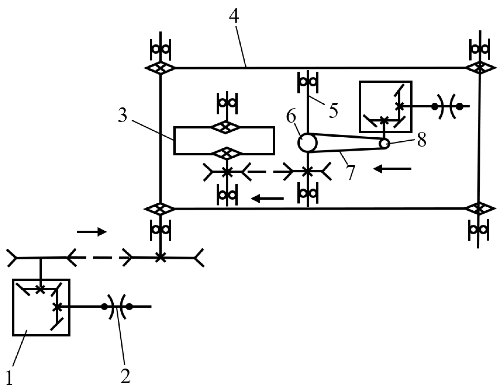
Figure 9.
Corn kernel external dimensions. (a) Flattened; (b) orbicular.

Figure 10.
Discrete metamodel of corn kernels. (a1) Flat-shaped grain entity; (a2) 3D model of flat grain; (a3) discrete flat-grain model; (b1) circular grain entity; (b2) 3D model of circular grain; (b3) discrete circular-grain model.
Figure 10.
Discrete metamodel of corn kernels. (a1) Flat-shaped grain entity; (a2) 3D model of flat grain; (a3) discrete flat-grain model; (b1) circular grain entity; (b2) 3D model of circular grain; (b3) discrete circular-grain model.
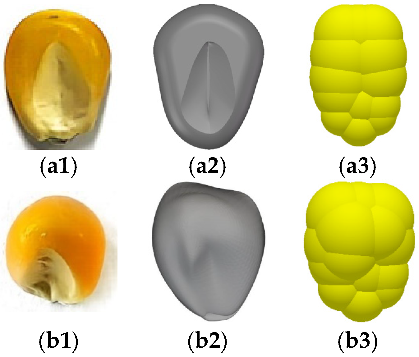
Figure 11.
Simulation model. (1) Corn model generation cylinder; (2) corn particles.

Figure 12.
Schematic diagram of simulated seed drop.
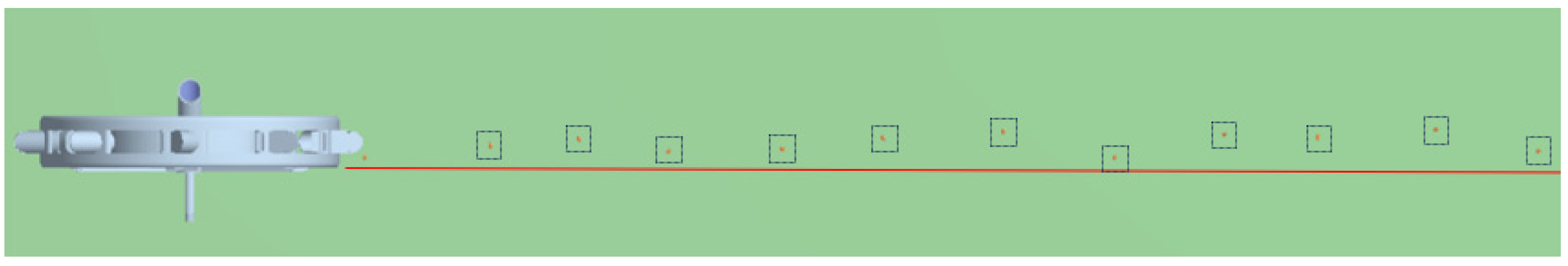
Figure 13.
Movable hole-formers with different lever angles: (a) for 110° lever; (b) seed not dropped for 110°, (c) 140°, and (d) 150° levers.
Figure 13.
Movable hole-formers with different lever angles: (a) for 110° lever; (b) seed not dropped for 110°, (c) 140°, and (d) 150° levers.

Figure 14.
Seed drop time vs. speed at different rotational speeds. (a) Speed = 40 r/min; (b) speed = 60 r/min; (c) speed = 80 r/min.
Figure 14.
Seed drop time vs. speed at different rotational speeds. (a) Speed = 40 r/min; (b) speed = 60 r/min; (c) speed = 80 r/min.
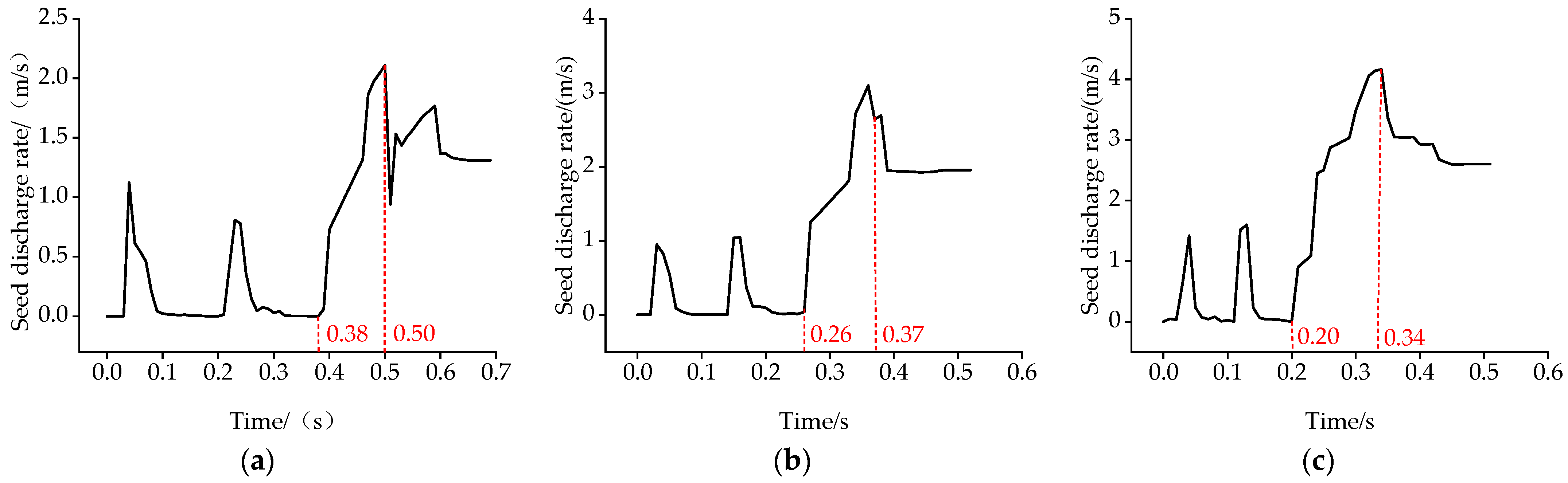
Figure 15.
Plot of number of bearings versus row index at different speeds.

Figure 16.
Effect of interaction of rotational speed of the rotating disc and angle of the lever on the response metrics. (a) Effect of the interaction of the rotational speed of the rotating disc and angle of the lever on the qualification index; (b) effect of the interaction of rotational speed of the rotating disc and angle of the lever on miss-seeding index; (c) effect of the interaction of rotational speed of the rotating disc and angle of the lever on the reseeding index.

Figure 17.
The influence of the interaction between the rotating speed of the moving disc and the number of bearings on the qualification index.
Figure 17.
The influence of the interaction between the rotating speed of the moving disc and the number of bearings on the qualification index.

Figure 18.
Bench test. (a) Diagram of the test bench operation and adjustment; (b) seedbed strip seeding maps.
Figure 18.
Bench test. (a) Diagram of the test bench operation and adjustment; (b) seedbed strip seeding maps.
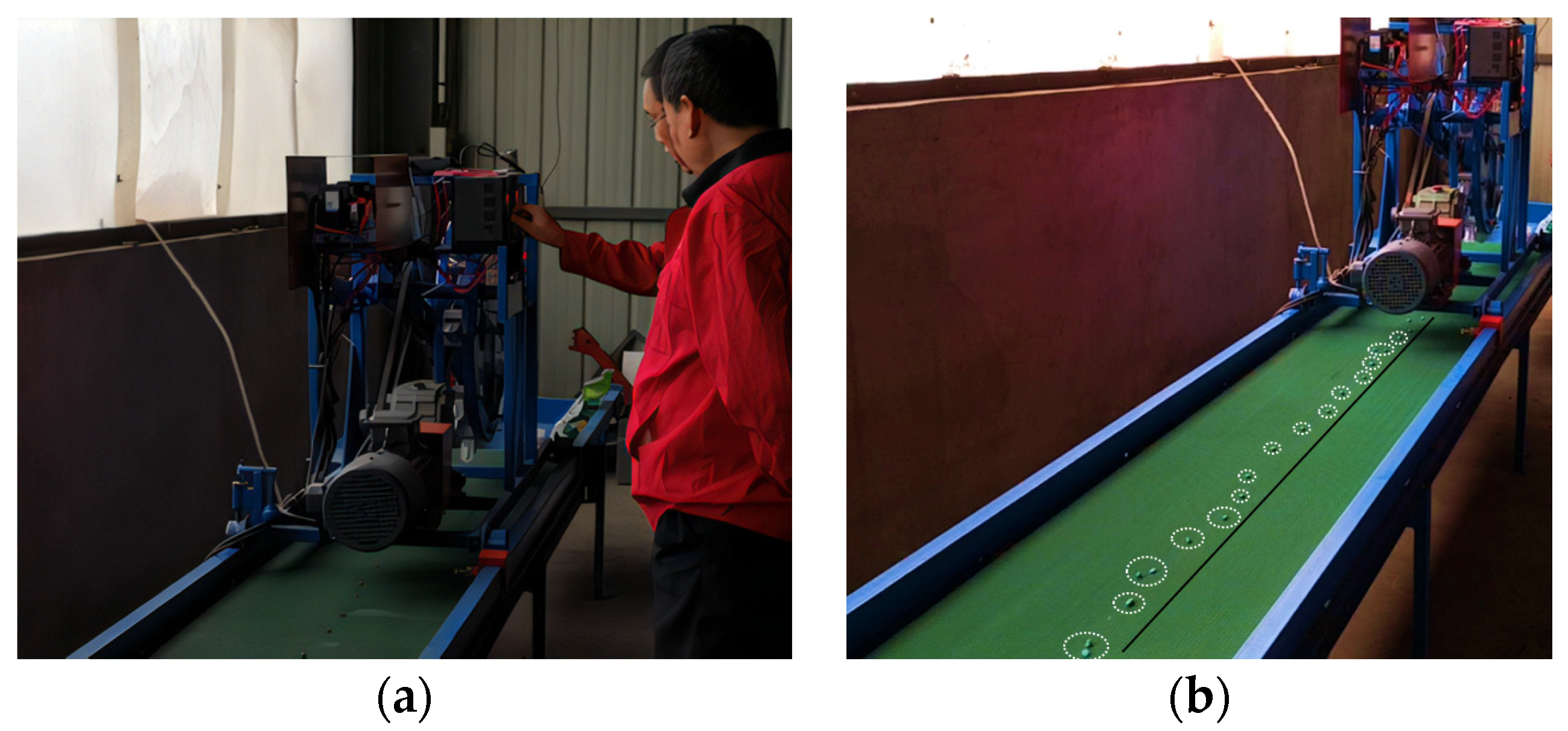
Figure 19.
Field test.


Table 1.
Triaxial geometric mean diameter of seeds.
| Shape | Average Length L/mm | Average Width W/mm | Average Thickness T/mm | Proportion |
|---|---|---|---|---|
| Flattened | 11.65 | 7.62 | 4.85 | 77.4% |
| Orbicular | 10.73 | 7.68 | 5.87 | 22.6% |
Table 2.
Material parameters of the simulation model.
| Material | Poisson’s Ratio | Shear Modulus/MPa | Density/(kg·m−3) |
|---|---|---|---|
| Corn | 0.357 | 2.17 × 10² | 1250 |
| Steel | 0.28 | 3.5 × 10⁴ | 7850 |
| Seed brush | 0.40 | 1 × 10² | 1150 |
| Rubber band | 0.48 | 1 × 10³ | 1380 |
Table 3.
Contact parameters of the simulation model.
| Form of Contact | Coefficient of Restitution | Coefficient of Static Friction | Coefficient of Rolling Friction |
|---|---|---|---|
| Corn–Corn | 0.60 | 0.50 | 0.10 |
| Steel–Corn | 0.60 | 0.30 | 0.01 |
| Seed Brush–Corn | 0.45 | 0.50 | 0.01 |
| Rubber Belt–Corn | 0.711 | 0.784 | 0.035 |
Table 4.
Test factor codes.
| Levels | Test Factors | ||
|---|---|---|---|
| Rotational Speed of Rotating Disc X1/(r·min−1) | Lever Angle X2/(°) | Pendulum Bearings X3/(Number) | |
| −1 | 40 | 110 | 3 |
| 0 | 60 | 125 | 4 |
| 1 | 80 | 140 | 5 |
Table 5.
Experimental project and results.
| Test No. | Factors | Response Values | ||||
|---|---|---|---|---|---|---|
| X1 | X2 | X3 | Y1/% | Y2/% | Y3/% | |
| 1 | −1 | 1 | 0 | 89.26 | 5.42 | 5.32 |
| 2 | −1 | 0 | 1 | 90.4 | 4.54 | 5.06 |
| 3 | −1 | 0 | −1 | 89.98 | 5.29 | 4.73 |
| 4 | −1 | −1 | 0 | 72.49 | 25.23 | 2.28 |
| 5 | 0 | 1 | 1 | 88.02 | 7.73 | 4.25 |
| 6 | 0 | 1 | −1 | 85.03 | 11.32 | 3.65 |
| 7 | 0 | 0 | 0 | 87.52 | 8.73 | 3.75 |
| 8 | 0 | 0 | 0 | 87.41 | 9.41 | 3.18 |
| 9 | 0 | 0 | 0 | 86.61 | 9.47 | 3.92 |
| 10 | 0 | 0 | 0 | 86.66 | 9.57 | 3.77 |
| 11 | 0 | 0 | 0 | 84.56 | 11.63 | 3.81 |
| 12 | 0 | −1 | 1 | 67.5 | 29.59 | 2.91 |
| 13 | 0 | −1 | −1 | 64.62 | 32.73 | 2.65 |
| 14 | 1 | 1 | 0 | 79.68 | 17.97 | 2.35 |
| 15 | 1 | 0 | −1 | 77.6 | 20.26 | 2.14 |
| 16 | 1 | 0 | 1 | 72.56 | 25.68 | 1.76 |
| 17 | 1 | −1 | 0 | 54.33 | 44.04 | 1.63 |
Table 6.
Variance analysis of the regression coefficients.
| Test Index | Sources of Variance | Square of Sum | Degree of Freedom | Mean Square | F-Value | p-Value |
|---|---|---|---|---|---|---|
| Qualification index | Model | 1765.11 | 9 | 196.12 | 207.28 | <0.0001 ** |
| X1 | 99.94 | 1 | 99.94 | 105.62 | <0.0001 ** | |
| X2 | 6.54 | 1 | 6.54 | 6.91 | 0.0340 * | |
| X3 | 7.58 | 1 | 7.58 | 8.01 | 0.0254 * | |
| X1X2 | 18.40 | 1 | 18.40 | 19.45 | 0.0031 ** | |
| X1X3 | 5.34 | 1 | 5.34 | 5.64 | 0.0493 * | |
| X2X3 | 0.0030 | 1 | 0.0030 | 0.0032 | 0.9565 | |
| X12 | 41.38 | 1 | 41.38 | 43.73 | 0.0003 ** | |
| X22 | 378.18 | 1 | 378.18 | 399.70 | <0.0001 * | |
| X32 | 2.58 | 1 | 2.58 | 2.72 | 0.1429 | |
| Residual error | 6.62 | 7 | 0.9462 | |||
| Lack-of-fit | 0.9668 | 3 | 0.3223 | 0.2279 | 0.8728 | |
| Error | 5.66 | 4 | 1.41 | |||
| Sum | 1771.74 | 16 | ||||
| Miss-seeding index | Model | 2088.30 | 9 | 232.03 | 190.83 | <0.0001 ** |
| X1 | 150.66 | 1 | 150.66 | 123.91 | <0.0001 ** | |
| X2 | 5.91 | 1 | 5.91 | 4.86 | <0.0001 ** | |
| X3 | 7.82 | 1 | 7.82 | 6.43 | 0.0044 ** | |
| X1X2 | 9.80 | 1 | 9.80 | 8.06 | 0.0251 * | |
| X1X3 | 5.45 | 1 | 5.45 | 4.48 | 0.0720 | |
| X2X3 | 0.0506 | 1 | 0.0506 | 0.0416 | 0.8441 | |
| X12 | 51.62 | 1 | 51.62 | 42.46 | 0.0003 ** | |
| X22 | 412.80 | 1 | 412.80 | 339.49 | <0.0001 ** | |
| X32 | 1.94 | 1 | 1.94 | 1.60 | 0.2469 | |
| Residual error | 8.51 | 7 | 1.22 | |||
| Lack-of-fit | 3.71 | 3 | 1.24 | 1.03 | 0.4685 | |
| Error | 4.80 | 4 | 232.03 | |||
| Sum | 2096.81 | 16 | 2.12 | |||
| Reseeding index | Model | 19.05 | 9 | 5.19 | 11.99 | 0.0018 ** |
| X1 | 5.19 | 1 | 0.0157 | 29.37 | <0.0001 ** | |
| X2 | 0.0157 | 1 | 0.0018 | 0.0888 | 0.0014 ** | |
| X3 | 0.0018 | 1 | 1.35 | 0.0103 | 0.2281 | |
| X1X2 | 1.35 | 1 | 0.0006 | 7.62 | 0.0281 * | |
| X1X3 | 0.0006 | 1 | 0.0289 | 0.0035 | 0.9542 | |
| X2X3 | 0.0289 | 1 | 0.5663 | 0.1636 | 0.6979 | |
| X12 | 0.5663 | 1 | 0.7578 | 3.21 | 0.1165 | |
| X22 | 0.7578 | 1 | 0.0449 | 4.29 | 0.0770 | |
| X32 | 0.0449 | 1 | 0.1766 | 0.2542 | 0.6296 | |
| Residual error | 1.24 | 7 | 0.2997 | |||
| Lack-of-fit | 0.8990 | 3 | 0.0843 | 3.55 | 0.1262 | |
| Error | 0.3373 | 4 | 2.12 | |||
| Sum | 20.29 | 16 |
Note: ** means very significant (p < 0.01); * means significant (0.01 < p < 0.05).
Table 7.
Results of bench test.
| Number | Qualification Index | Miss-Seeding Index | Reseeding Index |
|---|---|---|---|
| 1 | 87.60% | 7.60% | 4.80% |
| 2 | 92.40% | 4.00% | 3.60% |
| 3 | 91.60% | 5.20% | 3.20% |
| Average | 90.53% | 5.60% | 3.87% |
Disclaimer/Publisher’s Note: The statements, opinions and data contained in all publications are solely those of the individual author(s) and contributor(s) and not of MDPI and/or the editor(s). MDPI and/or the editor(s) disclaim responsibility for any injury to people or property resulting from any ideas, methods, instructions or products referred to in the content. |
© 2024 by the authors. Licensee MDPI, Basel, Switzerland. This article is an open access article distributed under the terms and conditions of the Creative Commons Attribution (CC BY) license (https://creativecommons.org/licenses/by/4.0/).
Share and Cite
MDPI and ACS Style
Zhou, H.; Dai, F.; Shi, R.; Zhao, C.; Deng, H.; Pan, H.; Zhao, Q. Simulation and Optimization of a Pendulum-Lever-Type Hole-Seeding Device. Agriculture 2024, 14, 750. https://doi.org/10.3390/agriculture14050750
AMA Style
Zhou H, Dai F, Shi R, Zhao C, Deng H, Pan H, Zhao Q. Simulation and Optimization of a Pendulum-Lever-Type Hole-Seeding Device. Agriculture. 2024; 14(5):750. https://doi.org/10.3390/agriculture14050750
Chicago/Turabian StyleZhou, Hengshan, Fei Dai, Ruijie Shi, Cai Zhao, Huan Deng, Haifu Pan, and Qinxue Zhao. 2024. "Simulation and Optimization of a Pendulum-Lever-Type Hole-Seeding Device" Agriculture 14, no. 5: 750. https://doi.org/10.3390/agriculture14050750
Note that from the first issue of 2016, this journal uses article numbers instead of page numbers. See further details here.