
Dynamic Testing of a Hybrid-Propellant Water-Breathing Ram Rocket in Underwater Cruise Conditions

1
Faculty of Aerospace Engineering, Technion—Israel Institute of Technology, Haifa 3200003, Israel
2
Missiles & Space Group, Israel Aerospace Industries, Lod 7010000, Israel
*
Author to whom correspondence should be addressed.
J. Mar. Sci. Eng. 2024, 12(5), 809; https://doi.org/10.3390/jmse12050809
Submission received: 16 April 2024
/
Revised: 3 May 2024
/
Accepted: 8 May 2024
/
Published: 13 May 2024
(This article belongs to the Section Ocean Engineering)
Abstract
:High-speed submerged marine vehicles, such as torpedoes, traveling at velocities of an order of 100 m/s and above, require powerful propulsion to overcome the tremendous hydrodynamic drag. This paper aims to investigate a marine hybrid-propellant water-breathing ram rocket (marine ramjet or ducted rocket) under various underwater cruise conditions. At high underwater cruise speeds, the ram rocket outperforms regular rocket motors, substantially increasing its specific impulse and thrust. This investigation utilized a unique test facility capable of dynamically testing the marine ramjet. Over 20 dynamic experiments have been conducted, revealing the submerged motor characteristics at different cruise speeds, water-to-propellant mass ratios, and oxidizer-to-fuel mass ratios, thereby creating a performance map of the marine ramjet. The results were compared with static firing data and theoretical calculations, showing a good agreement with standard specific impulse improvement of about 55% compared to a regular hybrid rocket, reaching a maximum value of 380 s. The significant increase in performance demonstrates the potential of the water-breathing ramjet for propelling high-speed underwater vehicles.
1. Introduction
Driving underwater vehicles at high velocities (e.g., torpedoes exceeding 100 m/s) demands a robust propulsion system capable of overcoming substantial hydrodynamic drag. Conventional propeller-based propulsion systems are efficient under relatively low velocities (up to about 25 m/s); as the cruise speeds increase, cavitation formation significantly reduces propeller efficiency, making it unsuitable for the mission. Solid propellant rocket propulsion has been considered an alternative for underwater vehicle propulsion since the 19th century [1], and recent studies exploring underwater hybrid rockets have been conducted [2]. Regardless of the medium (air or water), rockets offer high thrust-to-drag ratios and a relatively simple design, which is advantageous in terms of cost, weight, and maintenance. However, their energetic performance (specific impulse, ) and, hence, operating time and range are relatively low. To improve the energetic performance of the rocket motor, a propulsion system that efficiently utilizes the surrounding water emerges as a promising solution. Ambient water can function as an inert fluid to augment the mass flow rate ejected by the propulsion system, act as an oxidizer to react with hydro-reactive fuel components, or serve both roles. Like its aeronautical ducted rocket counterpart, the water-breathing ram rocket operates by utilizing its high dynamic (ram) pressure, resulting in an underwater high cruise velocity to ingest water into the combustion chamber without the use of any moving parts. The water is directed through an internal channel, reaching a mixing chamber, where the high-temperature combustion products cause it to boil, generating steam. This steam, along with the combustion products, is then accelerated through a nozzle, resulting in an exhaust jet that provides the necessary thrust for the vehicle propulsion. Gany [3] indicated that the marine water-breathing ducted rocket not only increases the energetic performance (higher specific impulse and lower specific fuel consumption) but it also increases the thrust/drag ratio compared to common rockets.
Water-breathing ramjets (ram rockets) have been studied in the past both theoretically and experimentally. Most of the theoretical works have explored the optimal performance of the motor, with a focus on using solid propellants with metal additives such as magnesium and aluminum [4,5,6,7,8]. In addition to theoretical investigations, experimental research on the combustion of various fuels with water has been conducted [9,10,11,12,13,14]. Only a limited number of studies have attempted experimental testing of a water-breathing ramjet, all of which only included several static firings of metal-rich solid propellants [15,16,17,18]. Eisen and Gany [19] pioneered the concept of using a marine water-breathing hybrid ram rocket motor. Generally, hybrid motor energetic performance (specific impulse) is better than that of solid propellant motors. Theoretical investigations revealed that this is also the case in marine ramjets for non-hydro-reactive fuels. In addition to theoretical calculations, Eisen and Gany [19] conducted numerous static firing tests under different oxidizer-to-fuel (O/F) and water-to-propellant (W/P) ratios. When compared to a common hybrid rocket, the specific impulse increased up to 70% with non-hydro-reactive fuels and nearly doubled when hydro-reactive metal additives such as aluminum and magnesium were incorporated in the fuel.
While static firing is commonly used for propulsion unit testing, it may not provide a complete picture regarding the actual operation. The cruise speed, which determines the stagnation pressure, plays a critical role in introducing the water into the motor and defining the actual operating conditions, such as the incoming water flow rate and combustion chamber pressure. Existing literature reports rely on experiments where water is forced into the motor from a pressurized water tank during static firing tests. Testing a marine water-breathing ramjet under actual cruise conditions would demonstrate the motor’s ability to operate and its performance without the need for forcing water into the motor artificially. Eisen and Gany [20] developed a test facility employing a water-breathing hybrid motor for underwater operations and reported on a single dynamic test. The present work aims at a parametric study of the performance of a submerged hybrid ram rocket under cruise conditions covering broad ranges of operating parameters of speed, water-to-propellant (W/P) ratio, and oxidizer-to-fuel (O/F) ratio. The test results are compared with static firing data found in ref. [19] and theoretical calculations obtained using the CEA thermochemical code [21].
2. Methods
2.1. Theoretical Evaluation
To assess the energetic performance of propulsion systems, a commonly employed metric is the specific impulse (), defined as the ratio of thrust generated () per mass flow rate of propellant (carried onboard) that is consumed to produce that thrust ( (see Equation (1)); is the standard gravitational acceleration. The higher the specific impulse, the better the energetic performance of the propulsion system.
The thrust equation for adapted nozzle is as follows:
where is the exit jet flow rate, is the exit jet velocity, is the incoming water flow rate, and is the vehicle velocity. The thrust coefficient was used to determine the adapted nozzle’s performance. The characteristic velocity ( represents the combustor’s energy and can express the exit jet velocity, Substituting the water-to-propellant mass flow rate ratio (W/P), one can obtain the following:
is expressed as follows:
where represents the ratio of specific heats and is defined as follows:
The water-to-propellant mass flow rate ratio (W/P) is defined as follows:
where and represent the fuel and oxidizer mass flow rates, respectively.
The characteristic velocity and specific heat ratio, which are necessary for these calculations, were obtained using the CEA thermochemical code [21]. Calculations were made for standard conditions of chemical equilibrium within the combustion chamber and isentropic expansion from 1000 psia (6.9 MPa) to 1 atm (ambient pressure) in the nozzle exit. The standard chamber pressure mentioned corresponds to the stagnation pressure achieved at an underwater cruise velocity of approximately 115 m/s. For these calculations, an initial temperature of 25 °C for the different ingredients was assumed. In line with the actual test conditions, gaseous oxygen and polyester were used as the oxidizer and fuel, respectively. The chemical formula of the polyester utilized was determined through the chemical analysis reported in ref. [19] as C42H41O10 and its enthalpy of formation, −886 kJ/mol. It is worth noting that the addition of large quantities of water may sometimes result in the product’s temperature decreasing below the boiling temperature of water (i.e., 557 K at 1000 psia (6.9 MPa)), potentially leading to an inaccurate computation by CEA. Therefore, theoretical results within a 10 K temperature range from the boiling temperature of the water have been excluded. Figure 1 illustrates the boiling temperature of water as a function of pressure.
2.2. Experimental Evaluation
2.2.1. Water Basin
The 10 m diameter water basin used for testing the water-breathing ramjet in actual cruise conditions is the one that was used and described in detail in ref. [20] (as illustrated in Figure 2). The test motor was submerged at an underwater depth of about 30 cm, permitting the assumption of atmospheric ambient pressure. It was attached to an arm rotating at a controllable speed by a central 31 kW electric motor, enabling underwater cruise velocities as high as 25 m/s.
2.2.2. Marine Ramjet (Ram Rocket)
The water-breathing ramjet used in this study employed polyester as its fuel and gaseous oxygen as its oxidizer. Fuel grains were formed by casting a liquid mixture of polyester resin with 1% (of the polyester mass) of hardener (methyl ethyl ketone peroxide) into an acrylonitrile butadiene styrene (ABS) 3D-printed casting mold. After the polyester fully solidified, the ABS mold was dissolved in acetone. This process is illustrated in Figure 3. Oxygen was stored in a cylinder mounted on the rotating arm base and was supplied to the motor through a tube running along the boom into the motor. The solid fuel grain served as both the motor casing and the chamber. Additionally, a 3D-printed ABS casing (which did not provide any strength advantages compared to polyester) was incorporated to enable the attachment of screw rods, connecting the motor components while preserving the hydrodynamic shape of the motor. A front-end inlet facilitated the flow of incoming water via an attached 3.95 mm inner diameter stainless steel tube with a thin protective zirconia layer. Controlled flow of oxygen was distributed around the water tube into the fuel grain central port. At the fuel grain’s rear end, where the water tube ended, a stainless steel aft-mixing chamber was located. It allowed evaporation and good mixing of the incoming water with the hot combustion products before expelling through the choked converging exit copper nozzle, whose throat diameter was varied from 6.85 to 8.0 mm. Figure 4 presents a picture of the motor and a section view sketch with the main dimensions.
For the ignition of the motor, a small cavity in the front section of the fuel provided space for a small mass of solid propellant. The solid propellant was ignited by a hot wire connected to two electrical wires exiting the motor through the oxygen inlet to a small battery situated on the rotating boom. To prevent water from entering the motor before ignition, the nozzle and inlet were sealed with a 3D-printed ABS cork and nylon sealing, respectively.
The experiment sequence began with the opening of the oxygen line, resulting in the ejection of the nozzle cork. This was followed by the closure of the hot wire circuit, allowing it to warm up and ignite the solid propellant. The hot gases from the propellant, combined with the oxygen flow, initiated the fuel’s ignition and flame spread. As a result, the nylon sealing for the water inlet was burned, allowing water to flow into the motor. A second later, the rotational arm accelerated the submerged motor to its designated velocity, ranging from 19 to 25 m/s. The experiment lasted for 8 s, concluding with the shutdown of the oxygen line.
Monitoring of the chamber pressure and the oxygen flow rate (measuring the upstream pressure of a 1.8 mm choked orifice) was carried out continuously (maximum error: ±2%). The total fuel mass consumed during the motor’s operation was determined by weighing the fuel grain before and after the experiment.
The actual values of the oxygen, fuel, and water flow rates, as well as the cruise speed and nozzle throat, affected the combustion pressure during each experiment. To enable comparison, a common basis was used by adjusting the actual measured specific impulse to equivalent values at standard conditions (i.e., chamber pressure of 1000 psia; 6.9 MPa) with the same efficiency. The adjustment was performed by multiplying the measured specific impulse by the ratio between the theoretical values of the thrust coefficient under standard conditions (Equation (4)) and the theoretical value under the actual conditions. In addition, to account for the momentum of the incoming water, vehicle velocity providing stagnation pressure equivalent to the standard pressure value, i.e., approximately 115 m/s, was used. The theoretical thrust coefficient for the actual choked convergent nozzle was calculated as follows:
Thermochemical calculations of were performed according to the conditions at each test.
The experimental characteristic velocity was derived from the test measurements using the following equation:
The calculation of the incoming water flow rate was based on the measured pressure and theoretical calculation from CEA. Assuming a combustion efficiency ( of 80%, which falls within the range of efficiencies observed in ref. [19] during static firings with identical propellant compositions, a value of the W/P ratio could be guessed; then, using CEA and the test results, the characteristic velocity was calculated in two different ways. The W/P value that minimized the difference between the measured and calculated characteristic velocity values was the chosen W/P ratio. A schematic flowchart outlining this calculation procedure is presented in Figure 5.
3. Results and Discussion
3.1. Theoretical Prediction
A theoretical presentation of the standard specific impulse and the chamber temperature for different O/F and W/P mass ratios is given in Figure 6. At the optimal conditions, i.e., O/F = 2.15 and W/P = 2, the increase in the overall exhaust jet flow rate due to the addition of water resulted in a noticeable enhancement in specific impulses compared to a rocket motor operation without water addition, yielding a peak specific impulse of 456 s. The inclusion of water decreases the chamber temperature; an excessive addition of water leads to a decrease in the exhaust velocity and motor performance. This reduction in chamber temperature limits the amount of water that can enter the motor based on the hot gas’s ability to evaporate it. Consequently, for high values of W/P ratios, the feasible range of O/F ratios narrows, as can be seen in Figure 6 for W/P ratios greater than two.
3.2. Experimental Results
3.2.1. Single Typical Experiment
Figure 7a–c displays the results of a typical experiment obtained during dynamic firing under underwater cruise conditions. Figure 7a presents the oxygen mass flow rate, starting before the ignition of the motor and showing a practically constant value of 5.5 g/s throughout the operation. Figure 7b displays the vehicle velocity, dictated by the central electric motor control, starting with a short period of zero motion, then increasing gradually to the desired operating velocity of 25 m/s, and remaining constant until the end of the test. Focusing on the motor pressure chamber (Figure 7c), the sequence begins with motor ignition reaching a “static” section (red color), characterized by the pressure resulting from the motor operation without the addition of water; this stage continues as long as the ram pressure (in green) is lower than the motor chamber pressure. Once the vehicle velocity reaches a sufficiently high level, i.e., the ram pressure exceeds the motor chamber pressure, water flows into the motor through the front inlet, causing the pressure to increase until it reaches the stagnation pressure at the desired velocity (approximately 4 s of dynamic section marked in blue). It results in a significant increase in motor thrust and specific impulse. Figure 8a presents a photograph of the motor shortly after ignition. Figure 8b presents a photograph of the water basin and the underwater moving vehicle during the dynamic experiment, revealing a bright flame observed through the translucent polyester fuel grain and casing of the motor.
3.2.2. Standard Specific Impulse
Over 20 experiments have been conducted under various conditions. The test data created a performance map of the motor under underwater cruise conditions, which was compared to static firing data reported in ref. [19] and theoretical calculations. Figure 9a–c shows the standard specific impulse versus the W/P ratio for different O/F ratios. The results reveal a significant increase in the specific impulse compared to a regular hybrid rocket, reaching a maximum actual specific impulse of 380 s at O/F = 1.95 and W/P = 2.16. Figure 10a–d presents the standard specific impulse versus the O/F ratio for different W/P ratio ranges. The results show good alignment with the static test data and follow the theoretical trends well, revealing an optimum in the O/F ratio close to the theoretical value of 2.15. All of the results show a significant increase in the standard specific impulse up to 55%. The test results reveal the superiority of the marine ramjet (ram rocket) over the rockets at a broad range of underwater cruise conditions.
3.2.3. Pressure Improvement
A key factor in the thrust augmentation of the marine ramjet is the stagnation (ram) pressure. According to Bernoulli’s theorem, as the cruise speed increases, the stagnation pressure increases quadratically:
where represents the ram (stagnation) pressure; is the ambient water pressure; and is the water density. Figure 11 illustrates the measured chamber pressure of the motor as a function of its speed, along with the theoretical ram pressure based on Equation (9). The majority of our test results reached the desired stagnation pressure, thereby increasing the motor pressure and thrust. However, in some cases, the difference between the motor chamber pressure and the ram pressure was relatively large, requiring better adjustments to the operating conditions. To address this issue, a suitable nozzle diameter ( needed to be designed for these specific conditions. This resulted in motor pressure values being closer to the ram pressure, leading to better performance under desired conditions, as shown in Figure 11 and marked in red and green. The improvement in the chamber pressure in each experiment due to water ingestion compared to its static section pressure versus the W/P ratio is presented in Figure 12. The overall trend indicates a substantial increase in pressure compared to the no-water-addition case with a rise in the W/P ratio, approaching 70% improvement in pressure. The dispersion in the results may be attributed to the static section pressure dependence on the propellant mass flow rate, which is not represented in the plot, as well as the different nozzle diameters used, generating higher chamber pressures for a smaller diameter.
4. Conclusions
This paper presents, to the best of our knowledge, actual data from the first parametric study of dynamic tests of a submerged water-breathing marine ramjet (ram rocket) under various cruise conditions. The results demonstrate the motor’s characteristics under various cruise speeds, O/F ratios, and W/P ratios. Compared to regular rocket motors, an increase in the standard specific impulse of up to 55% was measured, with a maximum value of 380 s at optimal conditions, proving the large potential in the use of the water-breathing ramjet for propelling high-speed underwater vehicles. The energetic performance can be further enhanced by including water-reactive additives in the fuel. This is the planned task for future investigations.
Author Contributions
Conceptualization, S.D., N.E.E. and A.G.; methodology, S.D., N.E.E. and A.G.; software, S.D. and N.E.E.; validation, N.E.E. and A.G.; formal analysis, S.D., N.E.E. and A.G.; investigation, S.D., N.E.E. and A.G.; resources, A.G.; data curation, S.D.; writing—original draft preparation, S.D.; writing—review and editing, S.D., N.E.E. and A.G.; visualization, S.D.; supervision, A.G.; project administration, A.G.; funding acquisition, A.G. All authors have read and agreed to the published version of the manuscript.
Funding
This research was partially funded by the PMRI—Peter Munk Research Institute, Technion, grant number 2070761.
Institutional Review Board Statement
Not applicable.
Informed Consent Statement
Not applicable.
Data Availability Statement
The original contributions presented in the study are included in the article, further inquiries can be directed to the corresponding author.
Acknowledgments
The authors wish to thank Rudy Kaner for his help with the motor design and manufacturing.
Conflicts of Interest
The authors declare no conflicts of interest.
References
- Kirby, G. A History of the Torpedo. J. R. Nav. Sci. Serv. 1972, 27, 30–42. [Google Scholar]
- Moon, H.; Han, S.; You, Y.; Kwon, M. Hybrid Rocket Underwater Propulsion: A Preliminary Assessment. Aerospace 2019, 6, 28. [Google Scholar] [CrossRef]
- Gany, A. Innovative Concepts for High-Speed Underwater Propulsion. Int. J. Energ. Mater. Chem. Propuls. (IJEMCP) 2018, 17, 83–109. [Google Scholar] [CrossRef]
- Yang, Y.J.; He, M.G. A Theoretical Investigation of Thermodynamic Performance for a Ramjet Based on a Magnesium-Water Reaction. J. Eng. Marit. Environ. 2010, 224, 61–72. [Google Scholar] [CrossRef]
- Yang, Y.J.; He, M.G. Thermodynamic Cycle Analysis of Ramjet Engines Using Magnesium-Based Fuel. Aerosp. Sci. Technol. 2012, 22, 75–84. [Google Scholar] [CrossRef]
- Yang, Y.; He, M. Numerical Study on Operating Characteristics of a Magnesium-Based Fuel Ramjet. Acta Astronaut. 2012, 79, 96–106. [Google Scholar] [CrossRef]
- Ghassemi, H.; Fasih, H.F. Propulsive Characteristics of Metal Fuel-Rich Pyrotechnics in Hydro-Reactive Motors. Aerosp. Sci. Technol. 2013, 28, 1–8. [Google Scholar] [CrossRef]
- Liu, D.; Li, S.; Xie, G. Effect of Primary Water Injection Angle on Thermal Propulsion Performance of a Water Ramjet Engine. Aerosp. Sci. Technol. 2020, 97, 2–15. [Google Scholar] [CrossRef]
- Huang, H.T.; Zou, M.S.; Guo, X.Y.; Yang, R.J.; Zhang, P. Analysis of the Solid Combustion Products of a Mg-Based Fuel-Rich Propellant Used for Water Ramjet Engines. Propellants Explos. Pyrotech. 2012, 37, 407–412. [Google Scholar] [CrossRef]
- Huang, H.T.; Zou, M.S.; Guo, X.Y.; Yang, R.J.; Li, Y.K. Analysis of the Aluminum Reaction Efficiency in a Hydro-Reactive Fuel Propellant Used for a Water Ramjet. Combust. Explos. Shock Waves 2013, 49, 541–547. [Google Scholar] [CrossRef]
- Huang, H.T.; Zou, M.S.; Guo, X.Y.; Yang, R.J.; Li, Y.K.; Jiang, E.Z.; Li, Z.S. Study of Different Al/Mg Powders in Hydroreactive Fuel Propellant Used for Water Ramjet. J. Energ. Mater. 2014, 32, 83–93. [Google Scholar] [CrossRef]
- Hu, J.; Han, C.; Xia, Z.; Huang, L.; Huang, X. Experimental Investigation on Combustion of High-Metal Magnesium-Based Hydroreactive Fuels. J. Propuls. Power 2013, 29, 692–698. [Google Scholar] [CrossRef]
- Ramakrishnan, M.; Chakravarthy, S.R.; Ganesan, S.; Jayaraman, K. Effect of Aluminum Particle Size on Primary Combustion and Performance of Water Ramjet. In Proceedings of the AIAA Propulsion and Energy Forum, AIAA Paper 2018-4959, Cincinnati, OH, USA, 9–11 July 2018. [Google Scholar] [CrossRef]
- Ramakrishnan, M.; Chakravarthy, S.R.; Kandasamy, J.; Sarathi, R. Development of Nano-Al Based Highly Metalized Fuel-Rich Propellant for Water Ramjet Propulsion Applications. Propellants Explos. Pyrotech. 2020, 45, 1026–1040. [Google Scholar] [CrossRef]
- Huang, L.; Xia, Z.; Hu, J.; Zhu, Q. Performance Study of a Water Ramjet Engine. Sci. China Technol. Sci. 2011, 54, 877–882. [Google Scholar] [CrossRef]
- Hu, F.; Zhang, W.; Xiang, M.; Huang, L. Experiment of Water Injection for a Metal/Water Reaction Fuel Ramjet. J. Propuls. Power 2013, 29, 686–691. [Google Scholar] [CrossRef]
- Ghassemi, H.; Farshi, F.H. Investigation of Interior Ballistics and Performance Analysis of Hydro-Reactive Motors. Aerosp. Sci. Technol. 2015, 41, 99–105. [Google Scholar] [CrossRef]
- Ramakrishnan, M.; Chakravarthy, S.R.; Kandasamy, J.; Sarathi, R. Experimental Investigation on Aluminum-Based Water Ramjet for Propelling High-Speed Underwater Vehicles. J. Propuls. Power 2023, 39, 886–895. [Google Scholar] [CrossRef]
- Eisen, N.E.; Gany, A. Investigation of a Marine Water-Breathing Hybrid Ram-Rocket Motor. J. Propuls. Power 2022, 38, 370–377. [Google Scholar] [CrossRef]
- Eisen, N.E.; Gany, A. Novel Testing of a Water-Breathing Naval Ramjet at Underwater Cruise Conditions. J. Propuls. Power 2022, 39, 242–248. [Google Scholar] [CrossRef]
- Gordon, S.; McBride, B.J. Computer Program for Calculation of Complex Chemical Equilibrium Compositions and Applications; Rept.RP-1311; NASA Lewis Research Center: Cleveland, OH, USA, 1994.
Figure 1.
Water boiling temperature (K) as a function of pressure (MPa).

Figure 2.
An illustration of the pool facility and the arm operated by the central electric motor for rotational motion control [20].
Figure 2.
An illustration of the pool facility and the arm operated by the central electric motor for rotational motion control [20].

Figure 3.
A schematic description of the casting procedure of the fuel grains.

Figure 4.
A photograph (upper panel) and section view sketch of the tested water-breathing hybrid ramjet (lower panel). The dimensions are in mm.
Figure 4.
A photograph (upper panel) and section view sketch of the tested water-breathing hybrid ramjet (lower panel). The dimensions are in mm.

Figure 5.
A schematic flowchart of the calculation procedure of the water-to-propellant ratio (W/P) evaluation.
Figure 5.
A schematic flowchart of the calculation procedure of the water-to-propellant ratio (W/P) evaluation.

Figure 6.
(a) Standard specific impulse,
(s), predicted by theoretical calculation vs. the W/P ratio spanning from 0 to 3, across various O/F ratios ranging from 0.5 to 3. (b) Standard specific impulse, (s), and (c) chamber temperature, predicted by theoretical calculation vs. the O/F ratio spanning from 0.1 to 5, across various W/P ratios ranging from 0 to 3.

Figure 7.
A typical underwater dynamic experiment at O/F = 1.8 and W/P = 0.6. (a) Oxygen mass flow rate; (b) vehicle cruise velocity; and (c) chamber pressure.
Figure 7.
A typical underwater dynamic experiment at O/F = 1.8 and W/P = 0.6. (a) Oxygen mass flow rate; (b) vehicle cruise velocity; and (c) chamber pressure.

Figure 8.
Photographs of (a) the tested marine ramjet after ignition, (b) the water basin, and the moving vehicle during the dynamic underwater experiment.
Figure 8.
Photographs of (a) the tested marine ramjet after ignition, (b) the water basin, and the moving vehicle during the dynamic underwater experiment.

Figure 9.
Theoretical, static [19], and dynamic (this study) standard specific impulses vs. W/P ratio for different O/F ranges: (a) O/F range 1.5–1.8; (b) O/F range 1.8–2.1; and (c) O/F range 2.1–2.6.
Figure 9.
Theoretical, static [19], and dynamic (this study) standard specific impulses vs. W/P ratio for different O/F ranges: (a) O/F range 1.5–1.8; (b) O/F range 1.8–2.1; and (c) O/F range 2.1–2.6.

Figure 10.
Theoretical, static [19], and dynamic (this study) standard specific impulses vs. O/F ratio for different W/P ranges: (a) W/P range 0.5–1; (b) W/P range 1–1.5; (c) W/P range 1.5–2; and (d) W/P range 2–2.5.
Figure 10.
Theoretical, static [19], and dynamic (this study) standard specific impulses vs. O/F ratio for different W/P ranges: (a) W/P range 0.5–1; (b) W/P range 1–1.5; (c) W/P range 1.5–2; and (d) W/P range 2–2.5.
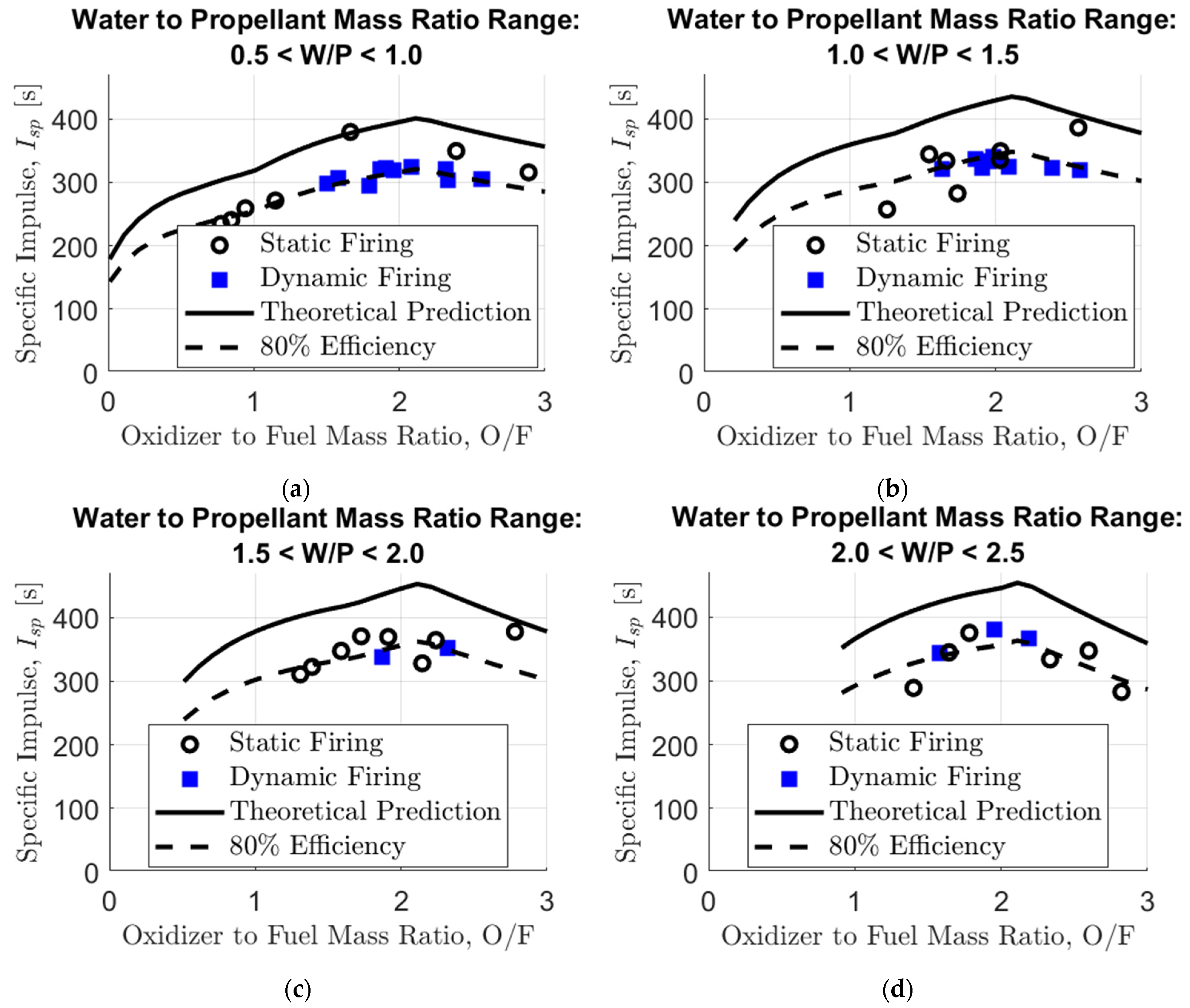
Figure 11.
The motor chamber pressure (
and ram pressure under different vehicle cruise velocities and nozzle diameters.
Figure 11.
The motor chamber pressure (
and ram pressure under different vehicle cruise velocities and nozzle diameters.

Figure 12.
Motor chamber pressure improvement (%) versus the W/P ratio, with different nozzle diameters.
Figure 12.
Motor chamber pressure improvement (%) versus the W/P ratio, with different nozzle diameters.

Disclaimer/Publisher’s Note: The statements, opinions and data contained in all publications are solely those of the individual author(s) and contributor(s) and not of MDPI and/or the editor(s). MDPI and/or the editor(s) disclaim responsibility for any injury to people or property resulting from any ideas, methods, instructions or products referred to in the content. |
© 2024 by the authors. Licensee MDPI, Basel, Switzerland. This article is an open access article distributed under the terms and conditions of the Creative Commons Attribution (CC BY) license (https://creativecommons.org/licenses/by/4.0/).
Share and Cite
MDPI and ACS Style
Dinisman, S.; Eisen, N.E.; Gany, A. Dynamic Testing of a Hybrid-Propellant Water-Breathing Ram Rocket in Underwater Cruise Conditions. J. Mar. Sci. Eng. 2024, 12, 809. https://doi.org/10.3390/jmse12050809
AMA Style
Dinisman S, Eisen NE, Gany A. Dynamic Testing of a Hybrid-Propellant Water-Breathing Ram Rocket in Underwater Cruise Conditions. Journal of Marine Science and Engineering. 2024; 12(5):809. https://doi.org/10.3390/jmse12050809
Chicago/Turabian StyleDinisman, Sagi, Nachum E. Eisen, and Alon Gany. 2024. "Dynamic Testing of a Hybrid-Propellant Water-Breathing Ram Rocket in Underwater Cruise Conditions" Journal of Marine Science and Engineering 12, no. 5: 809. https://doi.org/10.3390/jmse12050809
Note that from the first issue of 2016, this journal uses article numbers instead of page numbers. See further details here.