
Ceramic Matrix Composites: Classifications, Manufacturing, Properties, and Applications


1
Department of Mechanical Engineering, Dr. B. R. Ambedkar National Institute of Technology, Jalandhar 144011, PB, India
2
CSIR-Advanced Materials and Processes Research Institute, Bhopal 462026, MP, India
*
Author to whom correspondence should be addressed.
Ceramics 2024, 7(2), 652-679; https://doi.org/10.3390/ceramics7020043
Submission received: 28 December 2023
/
Revised: 26 February 2024
/
Accepted: 7 March 2024
/
Published: 10 May 2024
(This article belongs to the Special Issue Advances in Ceramics, 2nd Edition)
Abstract
:Ceramic matrix composites (CMCs) are a significant advancement in materials science and engineering because they combine the remarkable characteristics of ceramics with the strength and toughness of fibers. With their unique properties, which offer better performance and endurance in severe settings, these advanced composites have attracted significant attention in various industries. At the same time, lightweight ceramic matrix composites (LCMCs) provide an appealing alternative for a wide range of industries that require materials with excellent qualities such as high-temperature stability, low density, corrosion resistance, and excellent mechanical performance. CMC uses will expand as production techniques and material research improve, revolutionizing aerospace, automotive, and other industries. The effectiveness of CMCs primarily relies on the composition of their constituent elements and the methods employed in their manufacturing. Therefore, it is crucial to explore the functional properties of various global ceramic matrix reinforcements, their classifications, and the manufacturing techniques used in CMC fabrication. This study aims to overview a diverse range of CMCs reinforced with primary fibers, including their classifications, manufacturing techniques, functional properties, significant applications, and global market size.
1. Introduction
CMCs are a significant advancement in materials science and engineering because they combine the remarkable characteristics of ceramics with the strength and toughness of fibers [1,2]. Due to their distinctive qualities, which offer improved performance and durability in harsh environments, these advanced composites have attracted significant attention in various industries [3,4]. CMCs are a subgroup of composites, as well as ceramics, in material research. They comprise fibers or particles implanted in a ceramic matrix [5]. CMCs are renowned for their ability to tolerate extremely high temperatures and corrosion, and their lightweight and robust chemical stability, which means that they do not react with other chemicals or materials. Because of this, CMCs are ideal for applications with rigorous mechanical and thermal requirements [6]. The development of LCMCs, which offer superior performance in weight reduction and improved fuel efficiency, has attracted increasing interest in recent years. LCMCs have been developed to meet the demand for lightweight materials in aerospace, automotive, and energy [7,8]. Using lightweight fibers makes it possible to significantly reduce overall weight while maintaining high strength and stiffness, making them appealing for applications where weight reduction is crucial [9]. LCMCs have several characteristics compared to conventional materials. First, their low density helps reduce weight, enhancing fuel efficiency and expanding payload capacity in automobile and aeronautical applications [10]. They are also a suitable option for parts that must withstand extreme heat, like the turbine blades in gas turbines, due to their exceptional thermal stability and ability to withstand high temperatures. Strong wear resistance, low thermal expansion, and superior corrosion resistance further enhance CMC performance in demanding environments [11].
2. Classifications of Composites
Composites are categorized according to the type of reinforcement, i.e., fiber-reinforced, particle-reinforced, whisker-reinforced, and structural, based on the matrix. There are three types of composites: metal matrix composites (MMCs), polymer matrix composites (PMCs), and CMCs [12,13], as shown in Figure 1.
2.1. Metal Matrix Composites
This is a material class composed of a metal matrix reinforced by one or more secondary phases such as fibers, particles, or whiskers. These reinforcements increase the base metals’ mechanical, thermal, and electrical properties, resulting in a composite material with superior performance [14]. MMCs are typically produced through various manufacturing processes, such as liquid-state, solid-state, gas and vapor phases, and in situ synthesis. Making MMC liquid requires mixing a dispersed phase into a molten matrix metal before solidifying. The solid-state approach creates MMCs through bilateral diffusion between the matrix metal and the solid-state dispersion phase at high temperatures and pressure. In the in situ synthesis method, the reinforcement phase forms within the matrix through precipitation from the molten material as it undergoes the cooling and solidification process. In the gas and vapor phase, the fastest method is evaporation, which involves the thermal vaporization of the target species in a vacuum. Composite fabrication is typically completed by bundling and consolidating the coated fiber in a hot-pressing procedure [15]. MMCs have a range of attractive qualities that make them useful in a variety of applications. They also have excellent thermal conductivity, superior thermal stability, and customization capacity for specific purposes [16]. Titanium-matrix composites (TMCs), reinforced with either boron or silicon carbide (SiC), demonstrate favorable properties at room and elevated temperatures. This makes them an excellent material choice for aircraft fan blades operating under high-temperature conditions.
Meanwhile, MMCs are now employed in producing stiffness-critical components in missiles, replacing the previously used beryllium. The MMC features a high-volume fraction (40%) of particle-reinforced aluminum, offering a more cost-effective solution and eliminating toxicity concerns associated with beryllium. Additionally, MMCs contribute to lightweight construction and enhanced performance in sports equipment such as tennis rackets, bicycles, and golf clubs [17,18,19].
2.2. Polymer Matrix Composites
PMCs are a form of composite material that is made up of a polymer matrix that is reinforced with high-strength fibers. PMCs are made to transfer loads between a matrix’s fibers. PMCs have several benefits, including being lightweight, and exhibiting high resistance to abrasion and corrosion, and high strength and rigidity along the length of their reinforcements [20]. Their diverse manufacturing techniques include reaction molding, filament winding, the autoclave procedure, and manual lay-up [21]. PMCs provide a high strength-to-weight ratio, strong fatigue resistance, inherent resistance to corrosion, good electrical and thermal insulation qualities, and the ability to be extruded into complicated shapes and structures, giving PMCs a wide range of design choices. PMCs are suited for use in locations where they may be subjected to severe chemicals because they have good chemical resistance, excellent impact resistance, and a low coefficient of thermal expansion [22,23]. PMCs have a variety of uses because of their characteristics. PMCs are extensively used in the aerospace and aviation industries to create structural components such as wings, fuselages, engine parts, and rotor blades because of their excellent strength-to-weight ratio and fatigue resistance. In the automotive sector, PMCs are utilized for various purposes, including structural parts, body panels, and interior components. PMCs are also used as reinforcing elements to strengthen and extend the life of concrete structures.
Additionally, they are used to build facades, bridges, and other structural elements. PMCs are extensively used in the marine industry to construct boat hulls and other watercraft parts. Given that they are biocompatible, solid, and effectively resist fatigue, PMCs are used in medical applications like dental implants and prosthetic limbs.
2.3. Ceramic Matrix Composites
CMCs are a form of advanced material in which ceramic fibers are combined with a ceramic matrix. The matrix material, reinforcing material, and interphase material are the three primary components of CMCs. Each element is critical in determining the composites’ characteristics and performance [24].
2.3.1. Composition of CMCs
Matrix Material
In CMCs, the matrix material is often a ceramic compound that provides structural integrity and protects the reinforcement material. Matrix materials commonly used in lightweight CMCs include aluminum oxide (alumina), aluminosilicate (mullite), zirconium oxide (zirconia), and yttria-stabilized zirconia (YSZ), which are examples of oxide matrix material [25,26,27,28]. Carbon matrix (C), SiC, silicon nitride (Si3N4), zirconium carbide (ZrC), boron nitride (BN), and aluminum nitride (AlN) are some non-oxide matrix materials that are commonly employed [29,30,31].
Reinforcement Material
The reinforcement material in LCMCs gives the composite strength and rigidity. Fibers, whiskers, or particles are common forms of these materials [32]; the following are examples of common reinforcement materials used in LCMCs:
- Continuous fibers: As continuous reinforcements, carbon fibers and SiC fibers are often utilized [32].
- Discontinuous fibers: As discontinuous reinforcements, short fibers or whiskers, such as SiC whiskers, are employed [32].
- Particles: As reinforcement, nano- or micron-sized ceramic particles, such as SiC or alumina particles, can be employed [33].
Interface Material
In CMCs, the interphase material links the matrix and reinforcement, enhancing interface adhesion and effectively transferring stress. It aids in limiting the onset and spread of cracks at the interface [34]. For cracks in the matrix to deflect at the fiber–matrix interface and hence provide stress tolerance, the interface must have an energy-efficient crack progression area. CMCs, primarily SiC fiber/SiC matrix composites containing either carbon (C) or BN interphases, have been shown to have exceptional characteristics [35].
2.3.2. Classification of CMCs
CMC comes in various forms; typically, the classification uses the terms fiber and matrix (separated by a slash). For instance, C/SiC is a CMC consisting of a SiC matrix and C fibers. Non-oxide fibers for CMC are often constructed of SiC or C, while oxide fibers are made of alumina, mullite, or silica. C, SiC, and silicon mixes comprise most non-oxide matrices. Alumina, zirconium, mullite, and other aluminosilicates make up oxide matrices. Regular pairings involve oxide fibers with oxide matrices and non-oxide fibers with non-oxide matrices [36,37]. CMCs can be categorized based on the nature of the matrix of CMCs, i.e., oxide-CMC and non-oxide CMC, as shown in Figure 2 [38].
Oxide Ceramic Matrix Composites
Oxide ceramic matrix composites (O-CMC) combine ceramic fibers with ceramic matrices, specifically utilizing an oxide matrix. O-CMC enables various applications with severe thermal and mechanical requirements because it combines high-temperature stability, low density, high strength, and superior corrosion resistance with a damage-tolerant quasi-ductile fracture behavior [37]. O-CMCs include inorganic oxide compounds of metallic or metalloid elements with oxygen, including alumina, beryllia, ceria, and zirconia [38]. Furthermore, the application of O-CMCs is limited to scenarios with a maximum temperature of 1200 °C [39]. This restriction is attributed to the degradation of mechanical performance in the oxide reinforcing fibers, leading to reduced tensile strength values in the composite [40]. As illustrated in Figure 3, O-CMCs show a range of pairings; these mixtures fall into two categories: oxide/oxide matrices, in which the base material and filler/reinforcement are both oxides, and oxide/non-oxide matrices, in which the base material is an oxide but the filler/reinforcement is a non-oxide [38,41].
Non-Oxide Ceramic Matrix Composites
Due to their excellent mechanical and thermal properties, non-oxide CMC materials have received much research attention [38]. They contain a non-oxide base CMC and a filler or reinforcement (ceramic, metallic, plastic, polymer, etc.). Technical ceramics with covalent bonds, such as conductive carbides and non-conductive nitrides, comprise non-oxide CMCs [42]. Even though the components of non-oxide CMCs are incredibly brittle, their composition allows for excellent durability. Non-oxides have a low resistance to oxidation and corrosion when exposed to high temperatures [38]. Combinations of non-oxide CMCs exhibit diverse material qualities and demand specific manufacturing techniques, restricting their applicability to various industrial sectors. Based on the existing literature, non-oxide CMCs emerge as the predominant choice for high-temperature applications [43]. As illustrated in Figure 4, the composition of non-oxide CMCs consists of several matrices that can be employed as foundation materials and various fillers and reinforcements [38].
2.3.3. Processing Steps to Form CMCs
- Selecting raw material: Ceramic fibers and CMCs are chosen based on the final CMC product’s required qualities and performance requirements [44].
- Fiber treatment: Coatings can be applied to ceramic fibers to improve their adherence to the matrix material and interfacial bonding. This procedure enhances the fiber–matrix contact and optimizes the composites’ mechanical properties. Additionally, the interface must remain stable against thermal and environmental stress to prevent the deterioration of composite properties in high temperatures and corrosive conditions. Therefore, an interfacial coating is commonly applied during manufacturing to safeguard fibers from ecological damage [45].
- Perform fabrication: The fibers, also known as rovings, are laid up and attached using methods used to create fiber-reinforced plastics, such as filament winding, braiding, and knotting. Fiber-preform, or simply preform, is the process result [46].
- Interphase deposition: The interphase may be applied to the fiber surface during the filament manufacture or after the preform creation [47].
- Matrix infiltration/impregnation: The matrix material is infiltrated or impregnated into the preform, which can be a liquid precursor, polymer resin, or ceramic slurry. In this stage, the matrix material is introduced into the preform construction to fill the gaps between the fibers and form the required composite structure. This can be achieved by using techniques like Polymer Infiltration and Pyrolysis (PIP), Liquid Silicon Infiltration (LSI), sol-gel infiltration, and Chemical Vapor Infiltration (CVI) [48].
- Drying: Using controlled drying methods, any solvents or surplus moisture is removed from the impregnated preform [49].
- Thermal processing: To turn the preform that has been impregnated and dried into a ceramic matrix, it is subjected to thermal treatments like sintering in order to obtain the correct microstructure and characteristics of the CMC [50].
- Machining and shaping: After heat processing, the CMC structure may undergo machining and shaping procedures to obtain the desired final dimensions and surface polish. Cutting, grinding, drilling, and other machining processes may be used [51].
- Coating: Protective coatings, such as oxidation resistance, should be applied to the CMC structure to improve performance. Chemical vapor deposition (CVD), low-pressure chemical vapor deposition (LPCVD), or plasma spray are some methods that can be used to produce coatings. Slurries can also be painted to add a coating to the composite [52].
- Quality Control: Various quality control tests and inspections are conducted to ensure the final CMC product meets relevant specifications and standards. Non-destructive testing, mechanical testing, microstructural analysis, and other characterization procedures are examples of this [53].
- Final Finishing: Finishing techniques, such as finishing, coating, joining, and assembling, are used to produce the desired appearance and functionality of the CMC component [54].
3. Advanced Manufacturing Techniques
After mixing the powdered matrix material with the reinforcing phase, traditional ceramic manufacturing techniques, including hot pressing and sintering, can create CMCs. Such fabrication procedures successfully manufacture composites reinforced with a discontinuous phase (particulate or short fibers). However, due to mechanical damage to the fibers and their deterioration brought on by chemical interactions between the fiber and matrix materials at high sintering temperatures, composites reinforced with continuous or long fibers are rarely made using standard sintering techniques. Additionally, the fiber-reinforced composites produced using sintering processes have considerable porosity [55]. CMCs with extended fiber reinforcement are frequently created using infiltration techniques. In this class of fabrication methods, the woven or non-woven fiber structure is infiltrated with a fluid (gaseous or liquid) to make the ceramic matrix. The surface of the reinforcing fibers is coated with a debonding interphase that provides weak bonding at the interface between the fiber and matrix materials before the infiltration with a fluid obtained from ceramics. Weak bonding reduces brittle fracture by allowing the fiber to glide within the matrix [55].
3.1. Classification of Infiltration Techniques
Several infiltration procedures can be used to create CMCs, each with unique fluid types and methods for turning the fluid into a ceramic.
3.1.1. Polymer Infiltration and Pyrolysis
PIP is a technique for creating CMCs that involves introducing a low-viscosity polymer into a fabric-like ceramic reinforcement, which is then heated in an oxygen-free environment until the polymer breaks down and turns into a ceramic. Polymer-derived ceramics are ceramic materials made from polymers due to their pyrolysis. Preceramic polymers or polymer precursors are the terms used to describe the polymers that can be used to make ceramics [56]. The main structure of a PIP technique for creating a continuous ceramic composite with fiber reinforcement is as follows [56]:
- Generating pre-impregnated (prepreg) material: The reinforcing fibers are coated with a resin, the polymer’s viscosity is enhanced, and the prepreg can be formed [56].
- Lay-up: The tooling (mold) shapes the prepreg [56].
- Moulding: Molding is performed on the laid-up prepreg; different molding techniques can be applied. The prepreg is forced against the flexible top mold (bag) in the bag molding process by either atmospheric pressure (vacuum bag mold) or enhanced air pressure (gas pressure bag mold). The upper mold is flexible, in an autoclave, and the pressurized preform is cured. In compression molding, it is possible to combine pressure with a raised temperature [56].
- Preceramic polymer infiltration: When the preform is submerged in the reinforcing structure, a low-viscosity solution of a preceramic polymer fills the pores of the structure. Since capillary forces drive the infiltration process, it is typically carried out at atmospheric pressure, though it can also be vacuum- or pressure-aided [56].
- Pyrolysis: The preceramic polymer is pyrolytically decomposed between 800 and 1300 °C. Silicon nitride and other nitride matrices are produced under an environment of nitrogen (N2) or ammonia (NH3). As a result of the pyrolysis process, volatile compounds such as CO, H2, CO2, CH2, and H2O are emitted, giving the final ceramic matrix a porous structure. The weight loss (amount of emitted volatiles) determines the ceramic yield value [56].
- Re-infiltration and pyrolysis repeated several times: To reduce the ceramic matrix’s remaining porosity, the infiltration–pyrolysis cycle is repeated four to ten times [56].
Figure 5 illustrates a ceramic fiber preform immersed in a preceramic polymer, yielding PMCs. The PMC transforms into a CMC through pyrolytic decomposition, a sequential process iterated to diminish CMC porosity [56].
Advantages and disadvantages of PIP
The PIP technique is a primary approach for fabricating ceramic composites featuring SiC matrices. This method offers notable advantages [55]:
- Formation of ceramic matrices at comparatively low temperatures, thereby mitigating fiber damage.
- Precise control over the microstructure and composition of the ceramic matrix.
- Facilitation of net-shape fabrication for composite components.
- Accommodation of various reinforcement types (particulate, short, or continuous fibers).
- Ability to fabricate a broad spectrum of matrices, in contrast to the limitations of the melt infiltration (MI) method.
- Eliminating free silicon within the matrices, distinguishing it from the MI method.
Disadvantages of PIP:
- Lengthy fabrication times due to multiple infiltration and pyrolysis cycles.
- Higher production costs compared to the MI method.
- Presence of residual porosity within the matrix microstructure, impacting the mechanical properties of the composite.
3.1.2. Chemical Vapor Infiltration
The interphase and matrix are progressively deposited from gaseous precursors inside the pore network of a fiber performed during CVI. The chemical processes necessary for the deposition process must be initiated. This is accomplished by mildly heating the fiber preform (usually between 900 and 1100 °C) in either cold or hot wall reactors, with the latter typically favored. The deposition method is utilized to densify the fiber preforms before embedding them in the ceramic matrix; in CVI, two distinct processes are at play.
- Chemical reactions in the gas phase or on the fiber surface create the deposit. Methyltrichlorosilane, the most widely utilized preceramic gaseous precursor for the creation of composites with SiC matrix, decomposes as follows [57]:
CH3Cl3Si → SiC + 3HCl
- A mass transfer of gaseous reactants and products occurs outside and within the pore networks of the preforms [57].
The chemical processes are significantly more intricate and frequently involve intermediate gaseous species, with the gas phase maturing as it diffuses through the pores. Depending on the temperature, pressure, and gas/mass flow rate circumstances, convection or diffusion is used to transport the gaseous species mass. Typically, one of the most essential requirements for CVI is that the pores remain open through the densification process. There are various CVI process iterations, which can be categorized into five kinds [57]:
- Isothermal/isobaric (I-CVI);
- Temperature gradient (TG-CVI);
- Isothermal-forced flow (IF-CVI);
- Thermal gradient-forced flow (F-CVI);
- Pulsed flow (P-CVI).
The fabrication of CMC through the CVI process is the deposition of interphase by using the CVI approach, where a thin layer of hexagonal boron nitride (BN) or pyrolytic C is applied to the surface of the fiber [58]. The ceramic matrix is deposited using CVI; heat is applied to the preform before it is put into a reactor with a gaseous precursor. The gas infiltrates the preform, which creates a ceramic coating on the fiber surface as it breaks down. The process is repeated until the open porosity on the preform surface is sealed [58]. Illustrated in Figure 6 is a configuration wherein a preform is situated within a graphite chamber. The upper segment of the chamber is subjected to heating, while the lower section is maintained at a low temperature. The reactant gas is introduced into the chamber through the lower surface, undergoing deposition onto the preform in the heated region. Subsequently, the exhaust gas may exit from the upper surface.
Advantages and disadvantages of CVI
Advantages of the CVI method for the fabrication of CMCs [55]:
- The matrices exhibit high purity and good thermal shock resistance.
- The matrices display favorable creep and oxidation resistance at elevated temperatures (1400 °C) [18].
- The in situ deposition of interphases is possible, and residual mechanical stresses are kept low.
- The formation of matrices occurs at relatively low temperatures, minimizing fiber damage.
- The matrices demonstrate excellent mechanical properties, including strength, elongation, and toughness.
- The method allows the fabrication of various matrices such as SiC, C, Si3N4, BN, B4C, ZrC, etc.
Disadvantages of the CVI method:
- The process duration is extended, often spanning several weeks.
- The residual porosity levels are relatively high, typically 10% to 15%.
- The capital and production costs associated with the method are considerable.
3.1.3. Reactive Melt Infiltration
In the reactive melt infiltration (RMI) method, the ceramic matrix develops through a chemical interplay between the molten metal that permeates a porous reinforcing preform and the surrounding substance (whether solid or gaseous) upon the cooling process [55]. RMI is another pressure-less infiltration technique in which the passage of the liquid metal through the preform is aided mainly by capillary forces and surface tension. When one of the elements in the ceramic matrix has a low melting point and rapidly wets the fibers, RMI methods can be used [59]. This is true of aluminum alloys and even silicon; the former can produce an alumina matrix through a chemical reaction with an oxidizing environment (the process is known as direct melt oxidation (DMO)), whereas the latter can produce a silicon carbide matrix via a chemical reaction with a carbonaceous fiber preform (the process is known as liquid melt infiltration (LMI)) [57]. The reactive melt infiltration approach is quick and inexpensive. Moreover, this procedure yields materials characterized by minimal porosity and elevated thermal and electrical conductivity [60].
Direct Melt Oxidation
The DMO method for manufacturing CMC extends the RMI approach; it involves creating the matrix through a reaction between a molten metal and an oxidizing gas. In an oxygen-rich environment, a dispersed phase preform (comprising fibers or particles) is deposited onto the surface of a parent molten metal. Successful direct oxidation hinges on two factors: its affinity to the melt and its resistance to oxidation in an oxygen atmosphere. The liquid metal oxidizes upon encountering oxygen, forming a thin ceramic layer incorporating some dispersed phases. The capillary effect drives the molten metal through the porous ceramic layer to the reaction front, where it reacts with the gas, leading to the growth of the ceramic matrix layer. The movement of the molten metal is sustained, progressing to the reaction front at a rate dictated by the oxidation reaction speed. A portion of residual metal (approximately 5–15% of the material volume) remains within the intergranular voids of the ceramic matrix. The resulting materials lack the typical pores and impurities found in sintered ones [61]. The DMO process is commonly employed to fabricate composites using an aluminum oxide (Al2O3) matrix. In this method, a reinforcing preform (either in particulate or fibrous form, composed of SiC or Al2O3) is subjected to infiltration by a molten aluminum (Al) alloy within a furnace. The alloy is heated to temperatures from 900 to 1150 °C. Figure 7 illustrates that the DMO process involves placing the dispersed phase preform on the molten metal surface, exposed to oxygen [61]. The molten metal oxidizes upon contact, creating an oxidizing front that forms a thin ceramic layer with the dispersed phase. Capillary action drives the molten metal through the porous ceramic layer to the reaction front, where continuous metal–gas reactions occur, limiting the ceramic growth rate until reaching a barrier.
- Lay-up: The fibrous preform is formed during the lay-up stage.
- Interphases are used in the following ways: The CVI process involves depositing a thin layer (typically ranging from 0.1 to 1 micrometer) of a release phase (such as pyrolytic C or hexagonal BN) onto the fiber surface.
- Deposition of a gas-permeable barrier on the surface of the perform. The surface of the preform through which the melt should wick is not covered.
- DMO: Liquid Al alloy touches the preform; the melt permeates the supporting framework through the uncoated surface. The oxidant (air) enters the preform from the opposite side through the gas-permeable barrier. At the reaction front, Al and oxygen combine to produce the increasing layer of the oxide matrix. When the reaction front touches the barrier coating, the process is finished.
- Excess Al removal: The remaining Al on the part surface is removed.
Figure 7.
Synthesis of CMCs using direct melt oxidation.

Advantages and disadvantages of DMO
Advantages of the DMO method for the fabrication of CMCs [55]:
- The fabrication of near-net-shape parts is feasible due to minimal shrinkage.
- Equipment requirements are simple and cost-effective.
- The residual porosity is low, and raw materials are inexpensive.
- Mechanical properties, such as creep resistance, remain unaffected by impurities or sintering aids.
Disadvantages associated with the DMO method:
- The process rate is slow, with fabrication times typically ranging from 2 to 3 days.
- The presence of residual free aluminum within the oxide matrix is a notable drawback.
Liquid Melt Infiltration
When a liquid metal is infused into a porous reinforcing preform using the Liquid Silicon Infiltration (LSI) technique, a kind of RMI, the surrounding material (which may be solid or gaseous) and the melt interact chemically to create the ceramic matrix [62]. This method infuses molten silicon (Si) into a microporous C preform at a temperature higher than its melting point of 1414 °C. The liquid silicon moistens the surface of the C preform. Using capillary forces, the melt permeates the porous structure. The melt and C combine to generate SiC in the following reaction [62]:
Si(liquid) + C(solid) → SiC(solid)
The ceramic matrix is created when SiC, formed during the reaction, fills the preform pores. In general, the procedure entails the following steps [62]:
- Utilizing Interphases: CVI technology deposits a fine (typically ranging from 0.1 to 1 µm) layer of a detaching phase, such as hexagonal BN or pyrolytic C, on the fiber surface. Additionally, a barrier layer (usually SiC) shields the fibers from the highly reactive liquid silicon, whereas CVI is used to deposit the interphases.
- Manufacturing the prepreg: The reinforcement fibers used in tow, tape, and weave are resin-impregnated, dried out, or partly cured to B-stage. The resin C will continue to react with the silicon’s molten state.
- Lay-up: The prepreg is shaped by the tooling (mold).
- Moulding: The prepreg is molded after it has been laid up. Various molding techniques can be utilized; a hard lower mold is paired with a flexible top mold (bag) in the bag molding process, which is forced against the prepreg by either atmospheric pressure (vacuum bag mold) or enhanced air pressure (gas pressure bag mold). An autoclave is used to cure the pressurized preform. Compression molding can also achieve a mix of pressure and higher temperature.
- Pyrolysis: The preceramic polymer is pyrolytically decomposed in an Argon (Ar) environment at temperatures ranging from 800 to 1200 °C. As pyrolysis creates a porous carbon structure, volatile compounds are emitted.
- Initial machining: This operation may be undertaken following the molding and pyrolysis processes.
- Infiltration of the porous prepreg with liquid Si: The prepreg is submerged in molten Si in a furnace, where the melt seeps into its porous C structure. Capillary forces drive the infiltration process. When liquid Si combines with C, an in situ SiC matrix is formed.
Figure 8 illustrates a porous C matrix composite created through the pyrolysis of polymer-impregnated fibers at temperatures ranging from 800 to 1200 °C [62]. Subsequently, the C prepreg undergoes immersion in molten Si, facilitating the combination of liquid Si with C to generate a SiC matrix composite.
Advantages and disadvantages of LSI
Advantages of the LSI method for CMC fabrication [55]:
- Economical, feasible, and expedited production timelines.
- Elevated electrical conductivity and minimal residual porosity.
- Impressive thermal conductivity, reaching up to 40 W/mK [28].
- It enables the fabrication of intricate and near-net shapes.
Disadvantages associated with LSI:
- The infiltration process entails high temperatures, potentially risking fiber damage.
- Residual-free silicon may be present in the carbide matrix.
- Mechanical properties such as strength and modulus of elasticity tend to be lower [28].
3.1.4. Sol-Gel Infiltration
Figure 9 shows the progression of the sol–gel method of creating CMCs, where a liquid colloidal suspension of small ceramic particles (sol) is used to soak a preform before it solidifies (gel) [63]. Colloidal suspension is created due to a chemical process in which tiny particles (nanoparticles) with up to 100 nm radii precipitate within a liquid (water or organic solvent). Because liquid sols have a low viscosity, they easily penetrate the preform. At high temperatures, polycondensation or hydrolysis mechanisms cross-link (polymerize) sols containing organometallic compounds, such as alkoxides. Sol is converted into a liquid polymer structure gel through polymerization. Gels can be converted into ceramics at low temperatures, reducing the possibility of reinforcing fiber breakage. Alumina matrix ceramic composites can be made from alumina gel, formed via the hydrolysis (reaction with water) of Al alkoxides. Because the amount of ceramic in gels is relatively modest, they shrink significantly after drying. The densification of the ceramic matrix is frequently increased by repeating the infiltration–drying cycle until the desired density is reached. Ceramic particles can increase sol–gel’s volumetric output of ceramic even further. Additionally, using ceramic particles during the drying process lessens the occurrence of cracks.
The following steps are included in this process [63]:
- Preparation of the prepreg: The fibrous reinforcing material is soaked in the sol, allowing the sol to permeate the porous structure of the reinforcing phase. The use of a vacuum or pressure can assist in facilitating penetration.
- Formation of the lay-up: Using a mold to shape the prepreg.
- Gelation and drying process: The sol undergoes heating to 150 °C, transforming into a gel, then drying at temperatures reaching up to 400 °C. This phase involves the removal of water, alcohol, and organic volatile components from the material.
- Re-infiltration and gelation cycles: Multiple iterations of sol infiltration and gelation are executed until the desired densification is attained.
- At the firing temperature, the ceramic matrix is consolidated (sintered).
Figure 9.
Flowchart of synthesis of CMCs using sol–gel infiltration.

Advantages and disadvantages of sol–gel infiltration
Advantages of sol–gel infiltration [55]:
- It utilizes low processing temperatures, minimizing fiber damage.
- It offers precise control over matrix composition, and equipment costs are notably affordable.
- It facilitates near-net shape fabrication, mitigating machining expenses.
- It enables the production of sizable and intricate components.
Disadvantages associated with sol–gel infiltration:
- Pronounced shrinkage may lead to matrix cracking.
- The yield of ceramics is modest, necessitating repeated infiltration–gelation cycles.
- The resulting CMC exhibits lower mechanical properties.
3.1.5. Slurry Infiltration
A slurry is a mixture of ceramic particles suspended in a liquid carrier that may also include fillers and wetting agents. A slurry percolates into a porous reinforcing preform while creating ceramic matrix composites using the slurry infiltration technique. Capillary forces are what propel the infiltration process. The preform is dried and heat-pressed to create a CMC when the infiltration process is complete [64]. Slurry infiltration is utilized in the production of ceramic, ceramic–glass, and glass matrices:
- Alumina (Al2O3);
- Silica (SiO2);
- Glass;
- Mullite (3Al2O3∙2SiO2);
- Silicon carbide (SiC);
- Silicon nitride (Si3N4).
The slurry infiltration process is analogous to sol–gel infiltration for manufacturing CMCs, as shown in Figure 10 [64]. Due to the higher solid concentration, slurry infiltration generates a denser structure with less shrinkage during processing. Slurry infiltration under pressure or vacuum increases the density of the resulting ceramic composite. This process includes the following steps [64]:
- Infiltration of slurry: The reinforcing fibers flow through a slurry that penetrates the reinforcing phase’s porous structure. The capillary action is the primary force behind infiltration, but it can be aided by vacuum or pressure.
- Lay-up: A mandrel is wound with prepreg (infiltrated fibers), then dried, chopped, and laid up; after drying, the pieces are sliced and placed on the mold.
- Pressing at high temperatures: Hot pressing (sintering, densification) is performed at high temperatures and pressures to improve the diffusion of the ceramic material between the particles inserted into the fiber structure. The particles combine to form a low porosity densified composite.
Figure 10.
Flowchart of synthesis of CMCs using slurry infiltration.

Advantages and disadvantages of slurry infiltration
Advantages of slurry infiltration [55]:
- The resulting CMC demonstrates relatively low porosity, and exhibits commendable mechanical properties.
Disadvantages associated with slurry infiltration:
- Hot pressing operations entail high pressures, posing a risk of fiber damage.
- Ceramic particles within the slurry may pose a threat to fiber integrity.
- Hot pressing necessitates costly equipment, and the fabrication of large and intricate shapes proves challenging.
3.2. Other Manufacturing Processes
3.2.1. Electrophoretic Deposition (EPD)
During EPD, particles in a liquid medium are charged and coagulated while moving with an oppositely charged electrode. Because it decreases processing times and enhances the control of green body microstructures, this method has been chiefly used to manufacture oxide CMC matrices and fibers. Aqueous or non-aqueous solutions of ceramic particles and non-conductive or conductive fibers such as SiC-Nicalon and C reinforcements are employed as base material matrices in this production process. The fiber weave is placed in front of the deposition electrode during the production of non-conductive fibers, while the ceramic deposit forms on the electrode and grows around and through the fiber [65]. Figure 11 shows the EPD cell, with positively charged particles in suspension moving towards the cathode electrode [66].
3.2.2. Spark Plasma Sintering (SPS)
SPS is a modern sintering technology developed for the binding of fine-grained ceramics due to its capacity to sinter efficiently in a brief period, at a higher heating pace, and at a lesser sintering temperature [67]. SPS is a sintering technique that allows pulsed DC to travel simultaneously via the powders and the die. The spark that ignites at the particulate interface is thought to cause rapid heating, which speeds up the sintering procedure. Spark effect pressure, electric field diffusion, and joule heating are used to obtain maximum particle densification. This approach is most suited for the consolidation of nano-powders since it suppresses grain growth due to its short sintering time, as opposed to hot pressing and other conventional sintering methods that require a long dwelling time to achieve consolidation. In terms of application, SPS outperforms traditional consolidation techniques due to the improved densification of substrates due to brief sintering intervals, high consistency, the ease of functioning, reliability, and security, the accurate management of consolidation power, rapid sintering rate, elevated heating rates, and the lower temperature of sintering that is achievable. Figure 12 shows the process of SPS steps; the novel method via SPS comprises putting the initial powders into a graphite mold, and the sintering process is accomplished by simultaneously applying electric current and external pressure [68].
3.2.3. Directed Energy Deposition (DED)
Various terms are called DED, including laser-engineered net shaping, directed light fabrication, direct metal deposition, and 3D laser cladding. DED is a more intricate printing technique frequently used to fix or add more material to existing components [69]. Components for CMC can be produced using DED, an additive manufacturing process. It entails layer-by-layer melting and fusing ceramic powders or wires using a focused energy source, such as a laser or electron beam, to produce a solid structure. This technique may precisely control the deposition process [70]. A nozzle attached to a multi-axis arm makes up a standard DED machine. It delivers melted material onto the desired surface, where it hardens. Though the nozzle is not locked to one axis and can move in numerous directions, the process is conceptually comparable to material extrusion. The step-by-step process of DED is as follows [69]:
- A nozzle-equipped four- or five-axis arm rotates around a fixed object.
- The nozzle sprays material onto the object’s existing surfaces.
- Either a wire or powder form of the material is offered.
- After deposition, the material is melted using a laser, electron beam, or plasma arc.
- Layers of additional material are added and solidified, fixing or adding new material properties to the existing object.
In the depicted DED technique (Figure 13), a molten metal pool forms through a laser and controlled powder stream [71]. The laser, delivered coaxially, moves along with the superheated melt pool, solidifying into additive-manufactured layers. Inert gas minimizes oxidization, and thermal monitoring ensures real-time melt pool temperature and morphology control for enhanced part quality [71].
3.2.4. Laser-Based Fabrication
A laser-based manufacturing process allows the production of ceramic fiber composite structures without using furnace technology for the first time; the steps and 3D machining processing are shown in Figure 14 [72]. The technique is based on ceramic fibers being de-sized as bundles and coated with a powder solution. After drying, the coated fiber bundle is put in a specific pattern and locally treated with a laser so that the matrix material melts and hardens [73].
4. Properties of Lightweight CMCs
CMCs mix a ceramic matrix with reinforcing ceramic phases to produce materials with novel and better characteristics. The primary function of the ceramic reinforcement in CMC is to provide the brittle ceramic matrix with some toughness. Fillers can be added to the ceramic matrix during manufacturing to increase the ability to conduct electricity, heat expansion, and the degree of hardness. CMC has many appealing properties, including stability at elevated temperatures, resilience to thermal shock, a high degree of hardness, resistance to corrosion, lightweight, magnetically insensitive, and electrically inert properties, versatility in providing specific technical options, and resistance to catastrophic failure. Due to the combination of these features, CMCs are desirable replacements for conventional industrial processing materials such as high-alloy steels and refractory metals [74].
4.1. Mechanical Properties
Monolithic ceramics exhibit less bridging than CMCs; hence, they have a linear stress–strain curve. CMCs display nonlinear stress–strain curves, and nonlinearity appears to be a plastic deformation of the material, known as quasi-plastic. As the stress increases, the bridging effect leads to microcracks, which cause this phenomenon. Since the matrix material (monolithic ceramics) has a lower elastic modulus than the fibers employed in CMCs, the stress–strain slope steadily reduces as the load increases [75]. Figure 15 shows the stress–strain behavior of CMCs compared with monolithic ceramics [76].
Interface nanoparticle reinforcements, in addition to fiber reinforcement, improve the mechanical viability of CMC materials. These reinforcements have a high surface-to-volume ratio, allowing them to cover the interface completely. Because of this, even a modest loading of such reinforcements in a ceramic matrix may considerably improve mechanical qualities, including fracture toughness, wear resistance, and flexural strength [76]. During ceramic processing, exposure to high temperatures and pressure can lead to corrosion, oxidation, and the mechanical failure of the fiber matrix. A protective coating is applied using CVD to address these issues. However, CVD is an expensive technique with low deposition rates. An alternative approach, CLPC, involves thermally downsizing commercial fibers in a nitrogen environment. Subsequently, a polymeric precursor solution is continuously coated onto the fibers, followed by drying, curing, and calcination in an inert atmosphere to achieve a uniform and dense coating. Figure 16 compares bending and tensile strength for fibers reinforced with various materials [77,78].
4.2. Electrical Properties
Multiple parameters, including the matrix, porosity, filler type/ratio, and heat treatment, affect the thermal and electrical properties of CMCs. Due to the covalent bonds that make up the crystal structure of ceramics and CMCs, they make excellent electrical insulators. Adding conducting fillers, such as carbon/metallic particles, or altering their electronic structure can make these CMCs and ceramics electrically conductive [79,80]. The electron determines the electrical conductivity of a material’s mean free path, the shortest distance an electron can travel before being obstructed. The phonon’s mean free path in CMCs can be limited using fillers, lowering electrical conductivity. On the other hand, including a conductive filler can improve electrical conductivity by replacing the ‘insulating’ matrix with a conducting component, inhibiting the decreased phonon mean free path [81].
4.3. Thermal Properties
Due to the absence of ionic and metallic interaction, ceramics naturally have lower heat conductivities than substances like metals. The elements that affect electrical conductivity also affect a material’s thermal conductivity. AlN is one of the ceramics with a high thermal conductivity (140–180 W/mK) and a low thermal expansion coefficient [82]. This value, however, might differ significantly based on the processing circumstances, the starting material’s porosity, and whether sintering additives were used. Due to its low diffusive nature, sintering thick AlN is difficult; hence, an extremely high processing temperature of over 1900 °C in a reducing environment is used. Making CMCs with the addition of sintering aids was shown to be a successful tactic [83]. Table 1 depicts a few of the significant influencing properties that are mentioned.
4.4. Corrosive Resistivity
Ceramics are used in many applications, including heat exchange tubes, turbines, and aerospace, and are renowned for their exceptional corrosion resistance. At higher temperatures, metals and polymers are more likely to oxidize and are vulnerable to chemical assaults. For harsh environments, ceramic composites are selected because ceramics and CMCs have strong covalent bonds. CMCs are frequently applied as protective coatings to shield the base material from harm. Having a multilayer coating is one of the design alternatives for protective coating. Bond, active, and outer layers are frequently present, with the outer layer acting as an oxygen- and corrosion-resistant layer [89]. In SiC/C composites, the bond layer is fabricated on top of SiC, and either SiC or Si3N4 makes up the outer layer [90,91]. In the functional layer (central layer), combinations from the Si-B-C system are present; the three layers may also show signs of self-healing [77].
5. Applications of CMCs
5.1. Aerospace Industry
CMCs are used in advanced aerospace applications such as hypersonic flight vehicles, spacecraft re-entry thermal protection systems, and turbine engine components [92]. These structural CMCs have outstanding long-term mechanical qualities and maintain their properties despite severe temperature, pressure, and other environmental factors, such as moisture. The primary properties of CMCs required for aerospace applications include a reduced density, extreme temperature strength, hardness, superior performance-to-weight ratio, refractoriness, excellent insulating properties, energy collection, and reduced thermal conductance. In this situation, C/C-SiC composites exhibit improved tribological characteristics, lower densities, and higher damage tolerance for advanced friction systems in aerospace applications [93]. Several engine producers and research organizations are ramping up their efforts to employ CMCs in the thrust chamber components of rocket engines [94]. Fiber-reinforced CMCs (FRCMC) of C/SiC, SiC/SiC, and various other composites manufactured with CVI have been extensively used in aviation and aerospace applications due to their resistance to exceptional temperatures, higher treating point (>1400 °C), and strong mechanical properties, as well as toughness and excellent corrosion resistance [95,96]. For sophisticated aerospace applications, various CMC components include combustion chambers, parts for turbine engines (Figure 17), fuel distribution systems and valves, energy segments, lightweight elements, thermal safeguarding mechanisms, bearings, structures, and seals [97].
5.2. Automobile Industry
CMC products must have vital attributes connected to the automotive sector, such as superior strength, high resistance to wear, reduced CTE, refractoriness, self-lubrication characteristics, excellent insulation, energy storage, and high conductivity to heat. In CMC composites, the matrix is made of SiC, SiN, SiAlON, and Si3N4. In contrast, the reinforcement is made of in situ Si3N4, carbon fiber (CF), silicon carbide fiber (SiCf), silicon nitride fiber (Si3N4f), silicon carbide whisker (SiCw), and titanium boride (TiB2)/milled CF [98]. CMCs used in automotive and industrial parts include turbines for gas thermal engines, powertrain elements, converters for catalytic reduction, turbocharging systems, fixed barrier recuperators, gaskets for water pumps, and lower heat dissipation diesel [97].
5.3. Defence Industry
With the advancement of CMCs, the defense industries are fast expanding. Defense components must have several essential characteristics, including low weight, high specific strength, excellent fracture resilience, high wear resistance, and high heat conductivity [99]. Aerospace, automobile, and armor components (Figure 17) are all included in defense industry applications. Examples include armor for structures, machinery, and personnel, and integrated, layered armor employing FRCMC material layers [100,101]. Tank power trains, enhanced armor, propeller systems, ground-based support vehicles, elements of fuel injectors, armed forces weaponry, combat aircraft, submarine shaft seals (Figure 17), and tear-resistant accurate bearings are just a few examples of CMC parts used in the defense industry [97].
5.4. Chemical and Biomedical Industries
The use of ceramic-based advanced composite materials in biomedical research is fast expanding. Recently, unique bovine apatite-based ceramic composites for tissue engineering applications were created utilizing a novel impregnation process [102]. CMCs have also been used to make various implant materials [103,104]. For biomedical, biological, and chemical applications, CMCs should have a high degree of biocompatibility, solid strength, excellent fracture toughness, significant catalysis adsorption, high resistance to chemical attack, and durability against corrosion. In contrast, photocatalytic properties are crucial in the chemical industry to break down the organic compound. The current pattern in these materials is towards new CMCs [105]. Among the CMC components used in the chemical and biomedical industries are heat exchange systems (Figure 17), reformers, recuperators, refractory materials, nozzles, artificially created teeth, bones (Figure 17), and joints, cardiovascular valves, catalysts, and igniters [97].
5.5. Nuclear Industry
SiCf/SiC CMCs are extensively used in nuclear engineering as refractory matter. CMCs made of SiCf/SiC can be utilized under harsh conditions. To use CMCs in the nuclear industry, materials must have extreme temperature strength and excellent mechanical, chemical, thermal, and radiation properties. SiCf/SiC ceramic composites are emerging as promising materials for application in the nuclear industry due to their exceptional thermal, mechanical, and chemical stability. These composites exhibit remarkable properties such as extreme temperature strength, resistance to fracture, resistance to creep, resistance to corrosion, and resistance to thermal shock. The inherent radiation resistance in SiC significantly enhances their suitability for use in nuclear scenarios. Notably, SiC maintains excellent resistance to radiation, particularly in nuclear applications. Even when exposed to temperatures of 800–1000 °C, SiC displays minimal swelling, with saturation swelling levels of approximately 0.1–0.2%. This underscores the robust radiation stability of SiCf/SiC CMCs [106]. Within the nuclear sector, various components of CMC application include nuclear fuel cladding for nuclear fuel, control materials, materials for moderation, and components for reactor containment [97].

5.6. Oil Industry
Refractoriness, great insulation properties, thermal collection, heat conductivity, excellent strength, and a relatively low thermal expansion coefficient are the main characteristics of CMCs necessary for the oil sector [116,117]. CMC can also be utilized as a furnace liner, coke drum, and fractionator unit. CMC components in the oil sector include bearings, flow-regulating mechanisms, pumping systems, refinery furnaces, and blast sleeves (Figure 18) [97].
5.7. Power Generation
Electrical power industries demand excellent insulation against electricity, refractoriness, energy collection, conductivity to heat, muscular strength, high resistance to wear, a reduced coefficient of thermal expansion (CTE), and self-lubrication properties [97]. CMC components utilized in electrical power production applications include bearings, ceramic turbines for gas, elevated temperature elements, fuel cells made of solid oxide, and cleaners [97].
5.8. Magnetic and Electrical Engineering
Magnetic nano CMCs are used in a variety of innovative applications. CMCs have also been employed as electrical insulators in electrical applications [118]. CMCs must have insulation against electricity, conductivity to electricity, semi-conductivity, and dielectric, piezoelectric, and magnetic characteristics for diverse applications [97]. CMC components in electrical and magnetic engineering applications include memory, heating resistance, varistor sensors (Figure 18), integrated electronics substrates, multiple-layer capacitors that store energy, and advanced multiple-layer integrated circuits [97].
5.9. Thermal Engineering
CMCs with high stability in thermal conditions, refractoriness, reduced CTE, and conductivity to heat are required for thermal engineering applications. There are various high-temperature applications for commercially available CMCs. Conventional CMCs are only briefly exposed to temperatures above 1200 °C [119]. CMC components in thermal engineering applications include electrode materials, electronic device heat sinks (Figure 18), and high-temperature commercial furnace insulation [97].
5.10. Optical Engineering
CMCs’ primary optical engineering properties are condensation, luminescence, translucence, and conductance. Rare earth elements are doped into wide bandgap semiconductors to improve the visual characteristics of CMC materials for photonic applications [120]. Periodic earth emissions are authorized throughout the visible spectrum, including the wavelengths of red (Eu3+), green (Tb3+), and blue (Tm3+) in materials with a substantial bandgap (i.e., >3 eV). Conventional semiconductors like Si do not work well for specific technical applications because they generate rare earth emissions at average temperatures [121]. AlN/SiC CMCs that have recently been studied and found to be doped with various rare earth minerals are candidates to solve the issues above [122,123]. A novel family of praseodymium-doped CMCs exhibits simultaneous electrostriction, mechanoluminescence, and electroluminescence, converting electrical energy into mechanical energy. These can be employed in sensors and other versatile devices and are environmentally beneficial [124]. CMC components (Figure 18) for optical engineering include laser diodes, optical communication cables, heat-resistant transparent materials, and light-emitting porcelain [97].

6. Challenges and Future Directions
CMCs offer many characteristics that make them unique for a variety of applications. Nevertheless, it is challenging to locate any interior cracks or wear and tear in the components of the ceramic matrix. The main flaw of CMC is its brittleness, which can result in catastrophic component failure. More efficient repair methods are needed due to insufficient expertise and qualified labor. This makes reparability even more of a problem. Despite having a lengthy lifespan, CMC parts cannot be recycled for use in the same application. The lifespan of such components can be extended by raising public awareness of CMC repair methods and employing more trained and qualified employees [132]. Unlike the MI method, developing manufacturing techniques that do not produce extra Si that can volatilize and cause matrix fissures is one of the challenges facing CMCs as they advance.
Another problem is that Si-containing materials can lose material at high temperatures due to their interaction with water vapor. A multilayer environmental barrier coating (EBC) currently serves to lessen this recession, a known chemical reaction. If the requirement for this coating could be decreased or eliminated, the price of CMCs might decrease [133]. The high expense of the production process is also an obstacle to CMC application in commerce. It can be reduced by speeding up usage and slowing production [134]. Figure 19 illustrates the global market for CMCs, valued at USD 7.92 billion in 2021, and it is projected to expand to approximately USD 22.31 billion by 2030 with a CAGR of 12.2% [135].
High-temperature stability is anticipated to spur growth in addition to reduced weight and high strength [136]. The oxide segment’s market share will increase significantly during the expected timeframe. Advanced materials called oxides, like Al2O3 and ZrO2, combine ceramic elements with metal oxides. These materials are frequently employed in high-temperature fields like aerospace, defense, and energy that demand superior mechanical and thermal qualities. Alumina matrix composites (AMCs) and zirconia matrix composites (ZMCs) are examples of common oxide types. These materials are perfect for various applications due to their unique qualities [137]. The market expansion also depends on several variables, such as government support, improvements in manufacturing techniques, and rising demand for energy-efficient equipment. The rising demand for energy-efficient systems primarily drives the expansion of the CMC market. The market for CMCs has expanded due to the rising need for energy-efficient systems across various industries, including power production, oil and gas extraction, and chemical processing. CMCs are employed in high-temperature applications, including gas turbines and heat exchangers, to increase efficiency and cut emissions. A significant factor impacting the growth of the CMC market is its increasing application in the automotive sector. CMC is becoming increasingly popular in the automotive sector thanks to its high strength, lightweight, and corrosion resistance; utilizing CMC aids in lightening the load on the vehicle, increasing fuel efficiency, and lowering pollutants. In addition, the expansion of the CMC market needs to be improved by the lack of CMC standardization. Since there currently needs to be an industry standard for CMC, it is challenging for manufacturers and consumers to compare and rank various goods [137].
Figure 19.
The global market of CMCs will increase from 2021–2030.

CMCs find application in a limited number of high-cost scenarios due to the expensive nature of raw materials, fabrication processes, and inspection methods. Reducing the overall cost of CMCs could yield significant advantages in terms of extended lifespan and enhanced reliability compared to metals and monolithic ceramics. This cost reduction can be attained by intensifying research efforts focused on elevating temperature capabilities, design limits, and the overall longevity of ceramic-based materials and reinforcing fibers. Developing environmental barrier coatings and advancements in fabrication and testing techniques will be essential [38]. The growing demand for CMC is primarily fueled by the computer-based design of novel components. Finite Element (FE) simulations are instrumental in addressing intricate technical specifications, such as highly anisotropic loadings. CMCs exhibit their most significant competitive advantage when confronted with these sophisticated demands. Presently, extensive research is underway to comprehend the behavior of CMCs at micro- and meso-scales and to forecast the lifespan of CMC components under operational conditions [36].
7. Conclusions
CMCs have attracted much interest lately because of their great mechanical qualities, stability at high temperatures, and superior corrosion resistance. These materials are possible because they improve strength, hardness, and thermal conductivity compared to traditional monolithic ceramics. The development of CMCs, their methods of processing, and their various applications are all covered in detail in this review. Processing procedures and fabrication techniques, such as PIP, CVI, and reactive melt, are investigated in depth. The main mechanical characteristics of CMCs, including tensile strength, fracture toughness, and creep resistance, are also included in this paper. This paper discusses CMC’s thermal and chemical stability and mechanical qualities, clarifying why they are appropriate for high-temperature applications. It investigates how CMCs might be used in the aerospace, energy, automobile, and other industries. The assessment points out areas for additional study to overcome current restrictions and realize the full potential of CMCs. It provides an estimate of the growth of CMCs in the global market and offers an invaluable resource for scholars, engineers, and scientists interested in learning about the developments in CMCs. It also describes the framework for upcoming research and application in this quickly developing sector.
Author Contributions
Conceptualization, S.S., D.K.S., T.J. and D.K.R.; writing—original draft preparation, S.S.; writing—review and editing, D.K.R., T.J., D.P.M. and D.K.S.; supervision, D.K.S., T.J. and D.K.R.; All authors have read and agreed to the published version of the manuscript.
Funding
This research received no external funding.
Institutional Review Board Statement
Not applicable.
Informed Consent Statement
Not applicable.
Data Availability Statement
No new data were created or analyzed in this study.
Conflicts of Interest
The authors declare no conflicts of interest.
Nomenclature
| AMC | Alumina Matrix Composites |
| BN | Boron Nitride |
| CF | Carbon Fiber |
| CMCs | Ceramic Matrix Composites |
| CVD | Chemical Vapor Deposition |
| CVI | Chemical Vapor Infiltration |
| CTE | Coefficient of Thermal Expansion |
| DED | Directed Energy Deposition |
| DMO | Direct Melt Oxidation |
| EBC | Environmental Barrier Coating |
| EPD | Electrophoretic Deposition |
| Eu3+ | Wavelengths of Red |
| F-CVI | Thermal Gradient-Forced Flow |
| I-CVI | Isothermal/Isobaric |
| IF-CVI | Isothermal-Forced Flow |
| LCMCs | Lightweight Ceramic Matrix Composites |
| LPCVD | Low-pressure Chemical Vapor Deposition |
| LSI | Liquid Silicon Infiltration |
| MMCs | Metal Matrix Composites |
| Mullite | Aluminosilicate |
| O-CMC | Oxide Ceramic Matrix Composites |
| P-CVI | Pulsed Flow |
| PIP | Polymer Infiltration and Pyrolysis |
| PMCs | Polymer Matrix Composites |
| RMI | Reactive Melt Infiltration |
| SiCMC | Silicon Carbide Matrix Composites |
| SPS | Spark Plasma Sintering |
| Tb3+ | Green |
| Tm3+ | Blue |
| TMCs | Titanium Matrix Composites |
| TG-CVI | Temperature Gradient |
| YSZ | Yttria-stabilized Zirconia |
| ZMC | Zirconia Matrix Composites |
| Zirconia | Zirconium Oxide |
| Zork | Zirconium Carbide |
| AlN | Aluminum Nitride |
| Al2O3 | Aluminum Oxide |
| SiC | Silicon Carbide |
| SiCf | Silicon Carbide Fiber |
| SiCw | Silicon Carbide Whisker |
| Si3N4 | Silicon Nitride |
| Si3N4f | Silicon Nitride Fiber |
| TiB2 | Titanium Boride |
References
- Francis, J. Ceramic Matrix Composites: A Strong and Lightweight Material Solution. Res. Rev. J. Mater. Sci. 2022, 10, 1–2. [Google Scholar] [CrossRef]
- Chawla, K.K. Ceramic Matrix Composites. In Composite Materials; Springer: New York, NY, USA, 2012; pp. 249–292. [Google Scholar] [CrossRef]
- Shvydyuk, K.O.; Nunes-Pereira, J.; Rodrigues, F.F.; Silva, A.P. Review of Ceramic Composites in Aeronautics and Aerospace: A Multifunctional Approach for TPS, TBC and DBD Applications. Ceramics 2023, 6, 195–230. [Google Scholar] [CrossRef]
- Ceramic-Matrix Composites Heat Up. On Composite World. 2013. Available online: https://www.compositesworld.com/articles/ceramic-matrix-composites-heat-up (accessed on 12 June 2023).
- Sher, D. Novel process by HRL Laboratories creates 3D printed ceramic matrix composites. VoxelMatters, 2020. Available online: https://www.voxelmatters.com/novel-process-by-hrl-laboratories-creates-3d-printed-ceramic-matrix-composites/#:~:text=Ceramic%20matrix%20composites%20(CMCs)%20are,be%20considered%20a%20ceramic%20material (accessed on 30 June 2023).
- What are the Applications of Ceramic Matrix Composite (CMCS) Materials? On Cem-Wave. 2021. Available online: https://www.cem-wave.eu/blog/what-are-applications-ceramic-matrix-composite-cmcs-materials (accessed on 12 June 2023).
- Lightweight, Ultra-High-Temperature, CMC-Lined Carbon/Carbon Structures. on Tech Briefs. 2011. Available online: https://www.techbriefs.com/component/content/article/tb/pub/briefs/materials/9150 (accessed on 12 June 2023).
- Stojanovic, B.; Glisovic, J. Application of Ceramic Matrix Composite in Automotive Industry. Ref. Modul. Mater. Sci. Mater. Eng. 2021, 2, 275–292. [Google Scholar] [CrossRef]
- Fan, J.; Njuguna, J. An introduction to lightweight composite materials and their use in transport structures. Lightweight Compos. Struct. Transp. 2016, 3–34. [Google Scholar] [CrossRef]
- Eyring, G.; Bull, T.E. US Congress 1988 Office of Technology Assessment (1988). Polymer Matrix Composites, Advanced Materials by Design, OTA-E-351, Library of Congress Catalogue Card No. 87-619860, June 1988; pp. 71–95. Available online: https://www.princeton.edu/~ota/disk2/1988/8801/880106.PDF (accessed on 12 June 2023).
- Luthra, K.L. Ceramic Matrix Composites (CMCs) for Gas Turbine Applications. GE Corporate Research & Development Schenectady, NY 1230. Available online: https://www.electrochem.org/dl/ma/201/pdfs/1108.pdf (accessed on 27 August 2023).
- Priyanka, P.; Dixit, A.; Mali, H.S. High-Strength Hybrid Textile Composites with Carbon, Kevlar, and E-Glass Fibers for Impact-Resistant Structures. A Review. Mech. Compos. Mater. 2017, 53, 685–704. [Google Scholar] [CrossRef]
- Kopeliovich, D. Classification of Composites. SubsTech (Substances & Technologies). 2010. Available online: https://www.substech.com/dokuwiki/doku.php?id=classification_of_composites (accessed on 12 June 2023).
- Metal Matrix Composites. Wikipedia. Available online: https://en.wikipedia.org/wiki/Metal_matrix_composite (accessed on 12 June 2023).
- Tadesse, A.; Ganesh, S. An Overview on Metal Matrix Composite Processing and Al7075 Based Mechanical Properties. Int. J. Eng. Res. Technol. (IJERT) 2020, 9. Available online: https://www.ijert.org/research/an-overview-on-metal-matrix-composite-processing-and-al7075-based-mechanical-properties-IJERTV9IS090317.pdf (accessed on 27 August 2023).
- Girot, F.A.; Majidi, A.P.; Chou, T.W. Metal Matrix Composites. Encycl. Phys. Sci. Technol. 2003, 485–493. [Google Scholar] [CrossRef]
- Purant, A.N.; Joshi, R.R.; Mhetre, S.B.; Patil, A.A. Applications of Metal Matrix Composites in Modern Engineering. Int. Res. J. Eng. Technol. (IRJET) 2020, 7. Available online: https://www.irjet.net/archives/V7/i6/IRJET-V7I6846.pdf (accessed on 13 June 2023).
- Kiser, J.; Calomino, A.; Brewer, D.; DiCarlo, J.; Morscher, G.; Nguyen, Q. SiC/SiC composites for high-temperature applications. In Proceedings of the 7th International Conference on High-Temperature Ceramic Matrix Composites (HT-CMC 7), Bayreuth, Germany, 20–22 September 2020. [Google Scholar]
- Akhil, R. A Study on Recent Trends in the Applications of Metal Matrix Composites. Int. J. Res. Appl. Sci. Eng. Technol. 2018, 6, 172–180. [Google Scholar] [CrossRef]
- Polymer Matrix Composites. Wikipedia. Available online: https://en.wikipedia.org/wiki/Polymer_matrix_composite (accessed on 13 June 2023).
- Reddy, H.N.; Ganta, N. Overview of Manufacturing PMC’s. Int. J. Recent Res. Civ. Mech. Eng. (IJRRCME) 2020, 6, 4–7. Available online: http://www.paperpublications.org (accessed on 12 June 2023).
- Polymer Matrix Composites: Properties, Applications, and Advantages. Defencebridge. 2023. Available online: https://defensebridge.com/article/polymer-matrix-composites-properties-applications-and-advantages.html (accessed on 16 June 2023).
- Naslain, R. Design, preparation and properties of non-oxide CMCs for application in engines and nuclear reactors: An overview. Compos. Sci. Technol. 2004, 64, 155–170. [Google Scholar] [CrossRef]
- Li, L. Definition, Function, and Design of Interface in Ceramic-Matrix Composites. Interfaces of Ceramic-Matrix Composites: Design, Characterization and Damage Effects, First Edition. WILEY-VCH GmbH. 2020. Available online: https://application.wiley-vch.de/books/sample/352734778X_c01.pdf (accessed on 27 August 2023).
- Cawley, J. Binary Oxide Ceramics: Al2O3, ZrO2, Structure and Properties of. Encycl. Mater. Sci. Technol. 2001, 524–533. [Google Scholar] [CrossRef]
- Cui, K.; Zhang, Y.; Fu, T.; Wang, J.; Zhang, X. Toughening Mechanism of Mullite Matrix Composites: A Review. Coatings 2020, 10, 672. [Google Scholar] [CrossRef]
- Yttria Stabilized Zirconia, Wikipedia. Available online: https://en.wikipedia.org/wiki/Yttria-stabilized_zirconia (accessed on 13 June 2023).
- Heidenreich, B. Carbon Fibre Reinforced SiC Materials Based on Melt Infiltration. DLR e German Aerospace Center Institute of Structures and Design, Stuttgart, Germany. 2005. Available online: http://elib.dlr.de/52517/1/Paper_Heidenreich_C_fibre_reinforced_SiC_mat_based_on_MI_HTCMC6.pdf (accessed on 27 August 2023).
- Non-Oxide Ceramics. Ceramic Technology. 2013. Available online: http://old.vscht.cz/sil/keramika/Ceramic_Technology/SM-Lect-9-A.pdf (accessed on 13 June 2023).
- Scarponi, C. Carbon–carbon composites in aerospace engineering. Adv. Compos. Mater. Aerosp. Eng. 2016, 385–412. [Google Scholar] [CrossRef]
- Naslain, R.R. Processing of Non-Oxide Ceramic Matrix Composites: An Overview. CIMTEC 2006, 50, 64–74. [Google Scholar]
- Lamon, J.; Mazerat, S.; R’Mili, M. Reinforcement of Ceramic Matrix Composites: Properties of SiC-Based Filaments and Tows. Ceram. Matrix Compos. 2014, 1–26. [Google Scholar] [CrossRef]
- Azad, H.K.M.; Rahman, M.Z. Ceramic matrix composites with particulate reinforcements—Progress over the past 15 years. Ref. Modul. Mater. Sci. Mater. Eng. 2023. [Google Scholar] [CrossRef]
- Lamon, J. Influence of Interfaces and Interphases on the Mechanical Behavior of Fiber-Reinforced Ceramic Matrix Composites. Ceram. Matrix Compos. 2014, 40–64. [Google Scholar] [CrossRef]
- Tressler, R.E. Recent developments in fibers and interphases for high temperature ceramic matrix composites. Compos. Part A Appl. Sci. Manuf. 1999, 30, 429–437. [Google Scholar] [CrossRef]
- Raether, F. Ceramic matrix composites-an alternative for challenging construction tasks. Ceram. Appl. 2013, 1, 45–49. [Google Scholar]
- Jefferson, G.; Keller, K.A.; Hay, R.S.; Kerans, R.J. Oxide/Oxide Composites with Fiber Coatings. Ceram. Matrix Compos. 2008, 187–204. [Google Scholar] [CrossRef]
- Karadimas, G.; Salonitis, K. Ceramic Matrix Composites for Aero Engine Applications—A Review. Appl. Sci. 2023, 13, 3017. [Google Scholar] [CrossRef]
- Kaya, C.; Kaya, F.; Butler, E.; Boccaccini, A.; Chawla, K. Development and characterisation of high-density oxide fibre-reinforced oxide ceramic matrix composites with improved mechanical properties. J. Eur. Ceram. Soc. 2009, 29, 1631–1639. [Google Scholar] [CrossRef]
- Chawla, K.K. Ceramic Matrix Composite Materials Interface. In Ceramic Matrix Composites, 2nd ed.; Springer: New York, NY, USA, 2003; Volume 12, pp. 139–167. [Google Scholar] [CrossRef]
- Karadimas, G.; Salonitis, K.; Georgarakis, K. Oxide Ceramic Matrix Composite Materials for Aero-Engine Applications: A Literature Review. Adv. Transdiscipl. Eng. 2021, 15, 153–158. [Google Scholar] [CrossRef]
- Jacobson, N.S.; Opila, E.J. Oxidation and Corrosion of Non-oxide Ceramics. Ref. Modul. Mater. Sci. Mater. Eng. 2016. [Google Scholar] [CrossRef]
- Dhanasekar, S.; Ganesan, A.T.; Rani, T.L.; Vinjamuri, V.K.; Rao, M.N.; Shankar, E.; Dharamvir; Kumar, P.S.; Golie, W.M. A Comprehensive Study of Ceramic Matrix Composites for Space Applications. Adv. Mater. Sci. Eng. 2022, 2022, 6160591. [Google Scholar] [CrossRef]
- Yao, Y.; Sun, Z.; Li, X.; Tang, Z.; Li, X.; Morrell, J.J.; Liu, Y.; Li, C.; Luo, Z. Effects of Raw Material Source on the Properties of CMC Composite Films. Polymers 2021, 14, 32. [Google Scholar] [CrossRef] [PubMed]
- The Fibre/Matrix Interface in Ceramic Matrix Composites. Cem-Wave. 2021. Available online: https://www.cem-wave.eu/blog/fibrematrix-interface-ceramic-matrix-composites (accessed on 27 August 2023).
- Ceramic Matrix Composites. Wikipedia. Available online: https://en.wikipedia.org/wiki/Ceramic_matrix_composite (accessed on 27 August 2023).
- Naslain, R.; Dugne, O.; Guette, A.; Sevely, J.; Brosse, C.R.; Rocher, J.-P.; Cotteret, J. Boron Nitride Interphase in Ceramic-Matrix Composites. J. Am. Ceram. Soc. 1991, 74, 2482–2488. [Google Scholar] [CrossRef]
- Radhika, N.; Sathish, M. A Review on Si-Based Ceramic Matrix Composites and their Infiltration Based Techniques. Silicon 2022, 14, 10141–10171. [Google Scholar] [CrossRef]
- Liu, F.-H.; Shen, Y.-K.; Liao, Y.-S. Selective laser gelation of ceramic–matrix composites. Compos. Part B Eng. 2011, 42, 57–61. [Google Scholar] [CrossRef]
- Wang, J.; Yang, Z.; Duan, X.; Jia, D.; Zhou, Y. Microstructure and mechanical properties of SiCf/SiBCN ceramic matrix composites. J. Adv. Ceram. 2015, 4, 31–38. [Google Scholar] [CrossRef]
- An, Q.; Chen, J.; Ming, W.; Chen, M. Machining of SiC ceramic matrix composites: A review. Chin. J. Aeronaut. 2020, 34, 540–567. [Google Scholar] [CrossRef]
- Carney, C.M. Ultra-High Temperature Ceramic-Based Composites. Compr. Compos. Mater. II 2018, 5, 281–292. [Google Scholar] [CrossRef]
- Loveday, M.; Morrell, R. Standardisation of mechanical testing and quality control. Int. J. High Technol. Ceram. 1988, 4, 103–122. [Google Scholar] [CrossRef]
- Lewis, D., III; Singh, M. Post-Processing and Assembly of Ceramic-Matrix Composites. Mater. Handb. 2001, 21, 668–673. [Google Scholar] [CrossRef]
- Kopeliovich, D. Advances in manufacture of ceramic matrix composites by infiltration techniques. In Advances in Ceramic Matrix Composites, 2nd ed.; Woodhead Publishing Series in Composites Science and Engineering; Elsevier: Amsterdam, The Netherlands, 2018; pp. 93–119. [Google Scholar] [CrossRef]
- Kopeliovich, D. Fabrication of Ceramic Matrix Composites by Polymer Infiltration and Pyrolysis (PIP). SubsTech (Substances & Technologies). 2010. Available online: https://www.substech.com/dokuwiki/doku.php?id=fabrication_of_ceramic_matrix_composites_by_polymer_infiltration_and_pyrolysis_pip (accessed on 15 June 2023).
- Naslain, R.R. Ceramic Matrix Composites: Matrices and Processing. Encycl. Mater. Sci. Technol. 2001, 1060–1066. [Google Scholar] [CrossRef]
- Kopeliovich, D. Fabrication of Ceramic Matrix Composites by Chemical Vapor Infiltration (CVI). SubsTech (Substances & Technologies). 2010. Available online: https://www.substech.com/dokuwiki/doku.php?id=fabrication_of_ceramic_matrix_composites_by_chemical_vapor_infiltration_cvi (accessed on 15 June 2023).
- Wali, N.; Yang, J.-M. Reactive Melt-Infiltration Processing of Fiber-Reinforced Ceramic Matrix Composites. Ceram. Compos. Process. Methods 2012, 351–390. [Google Scholar]
- Kopeliovich, D. Fabrication of Ceramic Matrix Composites by Liquid Phase Infiltration. SubsTech (Substances & Technologies). 2010. Available online: https://www.substech.com/dokuwiki/doku.php?id=fabrication_of_ceramic_matrix_composites_by_liquid_phase_infiltration (accessed on 15 June 2023).
- Kopeliovich, D. Fabrication of Ceramic Matrix Composites by Direct Oxidation Process. SubsTech (Substances & Technologies). 2010. Available online: https://www.substech.com/dokuwiki/doku.php?id=fabrication_of_ceramic_matrix_composites_by_direct_oxidation_process (accessed on 15 June 2023).
- Kopeliovich, D. Fabrication of Ceramic Matrix Composites by Liquid Silicon Infiltration. SubsTech (Substances & Technologies). 2010. Available online: https://www.substech.com/dokuwiki/doku.php?id=fabrication_of_ceramic_matrix_composites_by_liquid_silicon_infiltration_lsi (accessed on 15 June 2023).
- Kopeliovich, D. Fabrication of Ceramic Matrix Composites by Sol-Gel Process. SubsTech (Substances & Technologies). 2010. Available online: https://www.substech.com/dokuwiki/doku.php?id=fabrication_of_ceramic_matrix_composites_by_sol-gel_process (accessed on 15 June 2023).
- Kopeliovich, D. Fabrication of Ceramic Matrix Composites by Slurry Infiltration. SubsTech (Substances & Technologies). 2010. Available online: https://www.substech.com/dokuwiki/doku.php?id=fabrication_of_ceramic_matrix_composites_by_slurry_infiltration (accessed on 15 June 2023).
- Manufacturing Process of Ceramic Matrix Composites, Scholarly Community Encyclopaedia. Available online: https://encyclopedia.pub/entry/43416 (accessed on 15 June 2023).
- Mehdipour, M.; Afshar, A.; Moakhar, R.S.; Mohebali, M. Colloidal and Electrophoretic Behavior of Chitosan-Bioactive Glass Coating on Stainless Steel 316L. J. Colloid Sci. Biotechnol. 2013, 2, 302–308. [Google Scholar] [CrossRef]
- Oguntuyi, S.D.; Johnson, O.T.; Shongwe, M.B. Spark plasma sintering of ceramic matrix composite of TiC: Microstructure, densification, and mechanical properties: A review. Int. J. Adv. Manuf. Technol. 2021, 116, 69–82. [Google Scholar] [CrossRef]
- Kopeliovich, D. Spark Plasma Sintering. SubsTech (Substances & Technologies). 2010. Available online: https://www.substech.com/dokuwiki/doku.php?id=spark_plasma_sintering (accessed on 26 June 2023).
- Directed Energy Deposition, Additive Manufacturing Research Group, Loughborough University. Available online: https://www.lboro.ac.uk/research/amrg/about/the7categoriesofadditivemanufacturing/directedenergydeposition/ (accessed on 15 June 2023).
- Svetlizky, D.; Das, M.; Zheng, B.; Vyatskikh, A.L.; Bose, S.; Bandyopadhyay, A.; Schoenung, J.M.; Lavernia, E.J.; Eliaz, N. Directed energy deposition (DED) additive manufacturing: Physical characteristics, defects, challenges and applications. Mater. Today 2021, 49, 271–295. [Google Scholar] [CrossRef]
- Bian, L.; Thompson, S.M.; Shamsaei, N. Mechanical Properties and Microstructural Features of Direct Laser-Deposited Ti-6Al-4V. JOM 2015, 67, 629–638. [Google Scholar] [CrossRef]
- Polenz, S.; Kunz, W.; Braun, B.; Franke, A.; López, E.; Brückner, F.; Leyens, C. Development of a System for Additive Manufacturing of Ceramic Matrix Composite Structures Using Laser Technology. Materials 2021, 14, 3248. [Google Scholar] [CrossRef]
- Kunza, W.; Steinborna, C.; Polenzb, S.; Braunc, B. Laser-based manufacturing of ceramic matrix composites. Lasers in Manufacturing Conference. 2021. Available online: https://wlt.de/sites/default/files/2021-10/additive_manufacturing_non-metals/Contribution_131_final.pdf (accessed on 27 August 2023).
- Park, S.-J.; Seo, M.-K. Types of Composites. Interface Sci. Technol. 2011, 18, 598–620. [Google Scholar] [CrossRef]
- Richardson, G.Y.; Lei, C.S.; Singh, R.N. Mechanical properties of ceramic matrix composites exposed to rig tests. In Proceedings of the 28th International Conference on Advanced Ceramics and Composites B: Ceramic Engineering and Science Proceedings; John Wiley & Sons, Inc: Hoboken, NJ, USA, 2004; Volume 25, pp. 153–159. [Google Scholar] [CrossRef]
- Properties of Ceramic-Matrix Composites. Academic Library—Free Online College e Textbooks -Info{at}ebrary.net. Available online: https://ebrary.net/179630/engineering/properties_ceramic_matrix_composites#236294 (accessed on 18 June 2023).
- Khaliq, J. Ceramic Matrix Composites (CMCs); Shyha, I., Huo, D., Eds.; Advances in Machining of Composite Materials: Conventional and Non-Conventional Processes; Engineering Materials; Springer: Berlin/Heidelberg, Germany, 2021; pp. 285–309. [Google Scholar] [CrossRef]
- Gadow, R.; Kern, F.; Ulutas, H. Mechanical properties of ceramic matrix composites with siloxane matrix and liquid phase coated carbon fiber reinforcement. J. Eur. Ceram. Soc. 2005, 25, 221–225. [Google Scholar] [CrossRef]
- Vandegoor, G.; van de Goor, G.; Sägesser, P.; Berroth, K. Electrically conductive ceramic composites. Solid State Ion. 1997, 101–103, 1163–1170. [Google Scholar] [CrossRef]
- Khaliq, J.; Jiang, Q.; Yang, J.; Simpson, K.; Yan, H.; Reece, M.J. Utilizing the phonon glass electron crystal concept to improve the thermoelectric properties of combined Yb-stuffed and Te-substituted CoSb3. Scr. Mater. 2013, 72–73, 63–66. [Google Scholar] [CrossRef]
- Galusek, D.; Galusková, D. Alumina Matrix Composites with Non-Oxide Nanoparticle Addition and Enhanced Functionalities. Nanomaterials 2015, 5, 115–143. [Google Scholar] [CrossRef]
- Wozniak, M.; Danelska, A.; Rutkowski, P.; Kata, D. Thermal conductivity of highly loaded aluminium nitride–poly(propylene glycol) dispersions. Int. J. Heat Mass Transf. 2013, 65, 592–598. [Google Scholar] [CrossRef]
- Streicher, E.; Chartier, T.; Boch, P.; Denanot, M.-F.; Rabier, J. Densification and thermal conductivity of low-sintering-temperature AlN materials. J. Eur. Ceram. Soc. 1990, 6, 23–29. [Google Scholar] [CrossRef]
- Noda, T. Advanced SiC-SiC Composites for Nuclear Application; Mahajan, Y.R., Johnson, R., Eds.; Handbook of Advanced Ceramics and Composites; Springer: Cham, Switzerland, 2020. [Google Scholar] [CrossRef]
- Lamon, J. Properties and Characteristics of SiC and SiC/SiC Composites. Compr. Nucl. Mater. 2012, 2, 323–338. [Google Scholar] [CrossRef]
- Luzzatto, C.; Morgana, A.; Chaudourne, S.; O’Doherty, T.; Sorbie, G. A new concept composite heat exchanger to be applied in high-temperature industrial processes. Appl. Therm. Eng. 1997, 17, 789–797. [Google Scholar] [CrossRef]
- van Roode, M.; Bhattacharya, A.K. Durability of Oxide/Oxide CMCs in Gas Turbine Combustors. In Proceedings of the ASME Turbo Expo 2012: Turbine Technical Conference and Exposition, Copenhagen, Denmark, 11–15 June 2012; pp. 475–485. [Google Scholar]
- Hua, Z.; Yao, G.; Ma, J.; Zhang, M. Fabrication and mechanical properties of short ZrO2 fiber reinforced NiFe2O4 matrix composites. Ceram. Int. 2013, 39, 3699–3708. [Google Scholar] [CrossRef]
- Cheng, L.; Xu, Y.; Zhang, L.; Luan, X. Corrosion of a 3D-C/SiC composite in salt vapor environments. Carbon 2002, 40, 877–882. [Google Scholar] [CrossRef]
- Niu, M.; Wang, H.; Su, L.; Fan, X.; Zhang, D.; Shi, J. SiC/(SiC+glass)/glass coating for carbon-bonded carbon fibre composites. RSC Adv. 2016, 6, 61228–61234. [Google Scholar] [CrossRef]
- Herrmann, M. Corrosion of Silicon Nitride Materials in Aqueous Solutions. J. Am. Ceram. Soc. 2013, 96, 3009–3022. [Google Scholar] [CrossRef]
- Ruggles-Wrenn, M.B.; Kurtz, G. Notch Sensitivity of Fatigue Behavior of a Hi-Nicalon™/SiC-B4C Composite at 1200 °C in Air and in Steam. Appl. Compos. Mater. 2013, 20, 891–905. [Google Scholar] [CrossRef]
- Krenkel, W.; Berndt, F. C/C–SiC composites for space applications and advanced friction systems. Mater. Sci. Eng. A 2005, 412, 177–181. [Google Scholar] [CrossRef]
- Schmidt, S.; Beyer, S.; Knabe, H.; Immich, H.; Meistring, R.; Gessler, A. Advanced ceramic matrix composite materials for current and future propulsion technology applications. Acta Astronaut. 2004, 55, 409–420. [Google Scholar] [CrossRef]
- Cao, X.; Lin, B.; Zhang, X. Investigations on grinding process of woven ceramic matrix composite based on reinforced fiber orientations. Compos. Part B Eng. 2015, 71, 184–192. [Google Scholar] [CrossRef]
- Papakonstantinou, C.; Balaguru, P.; Lyon, R. Comparative study of high temperature composites. Compos. Part B: Eng. 2001, 32, 637–649. [Google Scholar] [CrossRef]
- Pramanik, S.; Manna, A.; Tripathy, A.; Kar, K.K. Current Advancements in Ceramic Matrix Composites. In Composite Materials; Kar, K., Ed.; Springer: Berlin/Heidelberg, Germany, 2017; pp. 457–496. [Google Scholar] [CrossRef]
- Kaya, H. The application of ceramic-matrix composites to the automotive ceramic gas turbine. Compos. Sci. Technol. 1999, 59, 861–872. [Google Scholar] [CrossRef]
- Rosso, M. Ceramic and metal matrix composites: Routes and properties. J. Mater. Process. Technol. 2006, 175, 364–375. [Google Scholar] [CrossRef]
- Miguel, A.S. Composite Floor Armor for Military Tanks and the Like. US Patent US4404889, 20 September 1983. [Google Scholar]
- Strasser, T.E.; Atmur, S.D. Fiber Reinforced Ceramic Matrix Composite Armor. US Patent US6135006 A, 24 October 2000. [Google Scholar]
- Pramanik, S.; Ataollahi, F.; Pingguan-Murphy, B.; Oshkour, A.A.; Abu Osman, N.A. In Vitro Study of Surface Modified Poly(ethylene glycol)-Impregnated Sintered Bovine Bone Scaffolds on Human Fibroblast Cells. Sci. Rep. 2015, 5, 9806. [Google Scholar] [CrossRef] [PubMed]
- Oshkour, A.A.; Pramanik, S.; Shirazi, S.F.S.; Mehrali, M.; Yau, Y.-H.; Abu Osman, N.A. A Comparison in Mechanical Properties of Cermets of Calcium Silicate with Ti-55Ni and Ti-6Al-4V Alloys for Hard Tissues Replacement. Sci. World J. 2014, 2014, 1–9. [Google Scholar] [CrossRef] [PubMed]
- Pramanik, S.; Agarwal, A.; Rai, K. Chronology of total hip replacement and materials development. Trends Biomater. Artif. Organs 2005, 19, 15–26. [Google Scholar]
- Feng, X.; Guo, H.; Patel, K.; Zhou, H.; Lou, X. High performance, recoverable Fe3O4ZnO nanoparticles for enhanced photocatalytic degradation of phenol. Chem. Eng. J. 2014, 244, 327–334. [Google Scholar] [CrossRef]
- Jones, R.; Henager, C. Subcritical crack growth processes in SiC/SiC ceramic matrix composites. J. Eur. Ceram. Soc. 2005, 25, 1717–1722. [Google Scholar] [CrossRef]
- Advanced Materials for Next-Gen Turbines. Turbomachinary International. 2015. Available online: https://www.turbomachinerymag.com/view/advanced-materials-for-next-gen-turbines (accessed on 25 June 2023).
- Ceramic Matrix Composite Technology Is GE’s Centerpiece Jet Propulsion Strategy for the 21st Century. GE Aerospace. 2019. Available online: https://blog.geaerospace.com/technology/42869/ (accessed on 25 June 2023).
- utomotive Carbon Ceramic Brake Rotors. CMCMAT. Available online: https://www.cmcmat.com/ (accessed on 25 June 2023).
- Engine Valve: Definition, Construction, Types, and Working Explained in detail. The Mechanical Engineering.com. Available online: https://themechanicalengineering.com/engine-valve/ (accessed on 25 June 2023).
- Covert Tactical PRESS Body Armour NIJ IIIA (3A). Vestgaurd.CO.UK. Available online: https://www.vestguard.co.uk/vestguard-covert-tactical-press-body-armour-vest-nij-level-3a.html (accessed on 25 June 2023).
- How Does A Marine Propeller Shaft Seal Work. Pacific Marine and Industrial. Available online: https://www.pacificmarine.net/engineering/shaft-seal-systems/how-does-a-marine-dripless-propeller-seal-work.htm (accessed on 25 June 2023).
- Modular Thumb Implant. BIOPRO. Available online: https://bioproimplants.com/portfolio-view/modular-thumb-implant (accessed on 25 June 2023).
- Heat Transfer Equipment. EnggCyclopedia. Available online: https://enggcyclopedia.com/2011/05/heat-transfer-equipment/ (accessed on 25 June 2023).
- RLs for Nuclear Fuel and Cladding. Nuclear Engineering Internatonal. Available online: https://www.neimagazine.com/features/featuretrls-for-nuclear-fuel-and-cladding-4198959/ (accessed on 25 June 2023).
- Mateus, F.A.D.; Gualdrón, J.A.C. Mathematical Model for Refinery Furnaces Simulation. Cienc. Tecnol. Y Futuro 2010, 4, 89–99. [Google Scholar] [CrossRef]
- Filho, R.; Sugaya, M. A computer aided tool for heavy oil thermal cracking process simulation. Comput. Chem. Eng. 2001, 25, 683–692. [Google Scholar] [CrossRef]
- Amir; Kurtan, U.; Baykal, A. Rapid color degradation of organic dyes by Fe3O4@His@Ag recyclable magnetic nanocatalyst. J. Ind. Eng. Chem. 2015, 27, 347–353. [Google Scholar] [CrossRef]
- Merrill, G.B.; Morrison, J.A. High Temperature Insulation for Ceramic Matrix Composites. US Patent US6013592 A, 11 January 2000. [Google Scholar]
- Steckl, A.J.; Zavada, J.M. Photonic Applications of Rare-Earth-Doped Materials. MRS Bull. 1999, 24, 16–20. [Google Scholar] [CrossRef]
- Favennec, P.; L’Haridon, H.; Salvi, M.; Moutonnet, D.; Le Guillou, Y. Luminescence of erbium implanted in various semiconductors: IV, III-V and II-VI materials. Electron. Lett. 1989, 25, 718–719. [Google Scholar] [CrossRef]
- Weingärtner, R.; Torres, J.G.; Erlenbach, O.; de la Puente, G.G.; De Zela, F.; Winnacker, A. Bandgap engineering of the amorphous wide bandgap semiconductor (SiC)1−x(AlN)x doped with terbium and its optical emission properties. Mater. Sci. Eng. B 2010, 174, 114–118. [Google Scholar] [CrossRef]
- Weingärtner, R.; Erlenbach, O.; Winnacker, A.; Welte, A.; Brauer, I.; Mendel, H.; Strunk, H.; Ribeiro, C.; Zanatta, A. Thermal activation, cathodo- and photoluminescence measurements of rare earth doped (Tm,Tb,Dy,Eu,Sm,Yb) amorphous/nanocrystalline AlN thin films prepared by reactive rf-sputtering. Opt. Mater. 2006, 28, 790–793. [Google Scholar] [CrossRef]
- Wang, X.; Xu, C.; Yamada, H.; Nishikubo, K.; Zheng, X. Electro-Mechano-Optical Conversions in Pr3+-Doped BaTiO3–CaTiO3 Ceramics. Adv. Mater. 2005, 17, 1254–1258. [Google Scholar] [CrossRef]
- FC-BRS-01 Wall Sleeve. FuCare. Available online: https://www.fucare.com/products-blast-resistant-wall-sleeves/90.html (accessed on 25 June 2023).
- Types of Bearings. Fractory. Available online: https://fractory.com/types-of-bearings/ (accessed on 25 June 2023).
- MOFLAME Ceramic Infrared DIY Heating Gas Burner with Gas Intake Nozzle Parts for Outdoor Indoor Heater, BBQ Stove. Oxyhydrogen Burner. Ubuy. Available online: https://www.ubuy.co.in/product/1AF6484JA-moflame-ceramic-infrared-diy-heating-burner-with-gas-intake-nozzle-parts-for-outdoor-indoor-heater-bbq-stove (accessed on 25 June 2023).
- Silicon Carbide Varistors. Indiamart. Available online: https://www.indiamart.com/proddetail/silicon-carbide-varistors-6855178788.html (accessed on 25 June 2023).
- Multilayer Ceramic Chip Capacitors (MLCC). KYOCERA. Available online: https://ele.kyocera.com/en/product/capacitor/mlcc/ (accessed on 25 June 2023).
- Ceramic Heat Sink for LED Lighting. Indiamart. Available online: https://www.indiamart.com/proddetail/ceramic-heat-sink-for-led-lighting-7449542455.html (accessed on 25 June 2023).
- AlN Laser Diode Carriers—Ceramic Material. FindLight. Available online: https://www.findlight.net/lasers/semiconductor-lasers/semiconductor-laser-accessories/aln-laser-diode-carriers-ceramic-material (accessed on 25 June 2023).
- Materials and Chemicals—Ceramic Matrix Composites (CMCs) Market. Reports and Data. Available online: https://www.reportsanddata.com/report-detail/ceramic-matrix-composites-market (accessed on 26 June 2023).
- Commercialization of CMCs and Developments for Next-Gen Performance. Composite World. Available online: https://www.compositesworld.com/articles/the-next-generation-of-ceramic-matrix-composites (accessed on 20 June 2023).
- Parveez, B.; Kittur, M.I.; Badruddin, I.A.; Kamangar, S.; Hussien, M.; Umarfarooq, M.A. Scientific Advancements in Composite Materials for Aircraft Applications: A Review. Polymers 2022, 14, 5007. [Google Scholar] [CrossRef]
- Available online: https://www.nextmsc.com/report/ceramic-matrix-composites-market (accessed on 11 February 2024).
- Ceramic Matrix Composites Market Size, Share & Trends Analysis Report by Product (Oxide, Silicon Carbide, Carbon), By Application (Aerospace, Defense, Energy & Power, Electrical & Electronics), By Region, And Segment Forecasts, 2023–2030. Grand View Research. Available online: https://www.grandviewresearch.com/industry-analysis/global-ceramic-matrix-composites-market (accessed on 20 June 2023).
- Ceramic Matrix Composites (CMC) Market by Product, Application, and Geography—Forecast and Analysis 2023–2027. Technavio. Available online: https://www.technavio.com/report/ceramic-matrix-composites-cmc-market-industry-analysis (accessed on 20 June 2023).
Figure 1.
Classification of composites (based on matrix).

Figure 2.
Classification of CMCs based on the nature of the matrix.

Figure 3.
O-CMC material categories.

Figure 4.
Non-oxide CMC material categories.

Figure 5.
Synthesis of CMC using PIP.

Figure 6.
Synthesis of CMC using CVI.

Figure 8.
Synthesis of CMCs using LSI.

Figure 11.
EPD cell process.

Figure 12.
Illustration of SPS process.

Figure 13.
Directed energy deposition process.
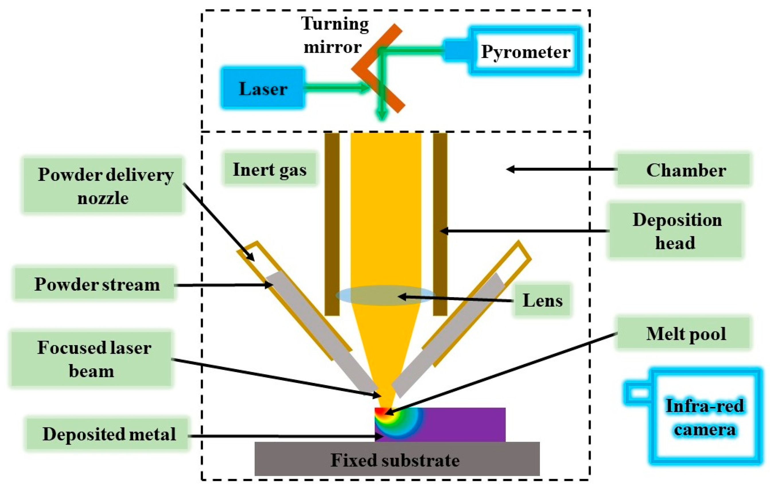
Figure 14.
Additive manufacturing of CMC using a laser-embedded system [72].
Figure 14.
Additive manufacturing of CMC using a laser-embedded system [72].

Figure 15.
Stress–strain behavior of CMCs, compared with monolithic ceramics [76].
Figure 15.
Stress–strain behavior of CMCs, compared with monolithic ceramics [76].

Figure 16.
Comparing the bending strength of composites to the tensile strength of reinforcement fibers involves exploring three densification cycles, utilizing the matrix polymer wacker silres H62 C, and subjecting the material to calcination at a temperature of 750 °C [78].
Figure 16.
Comparing the bending strength of composites to the tensile strength of reinforcement fibers involves exploring three densification cycles, utilizing the matrix polymer wacker silres H62 C, and subjecting the material to calcination at a temperature of 750 °C [78].


Table 1.
Comparative properties of various CMCs.
| Material | Density (g/cm3) | Strength (MPa) | Young’s Modulus (GPa) | Coefficient of Thermal Expansion × 10−6 (/K) | Thermal Conductivity (W/m-K) | References | |
|---|---|---|---|---|---|---|---|
| SiC/SiC by FCVI | 2.6–2.7 | ~16 | 260–300 (Tensile) | 140–160 | ~4 | ~15 | [84] |
| NicalonTM SiC/SiC by CVI | 2.5 | 30 | 200 (Tensile) | 230 | 3 | 19 | [85] |
| Hi-NicalonTM SiC/SiC by CVI | 2.2 | _ | 324 (Tensile) | 207 | _ | _ | [85] |
| NITE-Tyranno-SA3 SiC/SiC | 3.11 | _ | 408 (Tensile) | 358 | _ | 32 | [85] |
| SiCp/Al2O3 | 3.4 | 7.5 | 346 (Bending) | 341 | 7 | 85 | [86] |
| Nextel 720/Al2O3 by Sol-Gel | ~2.77 | _ | 175–197 (Tensile) | 73 | 3.5 | 3 | [87] |
| ZrO2(f)/NiFe2O4 | 5.13 | 4.62 | 88.92 (Bending) | _ | _ | _ | [88] |
Disclaimer/Publisher’s Note: The statements, opinions and data contained in all publications are solely those of the individual author(s) and contributor(s) and not of MDPI and/or the editor(s). MDPI and/or the editor(s) disclaim responsibility for any injury to people or property resulting from any ideas, methods, instructions or products referred to in the content. |
© 2024 by the authors. Licensee MDPI, Basel, Switzerland. This article is an open access article distributed under the terms and conditions of the Creative Commons Attribution (CC BY) license (https://creativecommons.org/licenses/by/4.0/).
Share and Cite
MDPI and ACS Style
Shrivastava, S.; Rajak, D.K.; Joshi, T.; Singh, D.K.; Mondal, D.P. Ceramic Matrix Composites: Classifications, Manufacturing, Properties, and Applications. Ceramics 2024, 7, 652-679. https://doi.org/10.3390/ceramics7020043
AMA Style
Shrivastava S, Rajak DK, Joshi T, Singh DK, Mondal DP. Ceramic Matrix Composites: Classifications, Manufacturing, Properties, and Applications. Ceramics. 2024; 7(2):652-679. https://doi.org/10.3390/ceramics7020043
Chicago/Turabian StyleShrivastava, Shriya, Dipen Kumar Rajak, Tilak Joshi, Dwesh K. Singh, and D. P. Mondal. 2024. "Ceramic Matrix Composites: Classifications, Manufacturing, Properties, and Applications" Ceramics 7, no. 2: 652-679. https://doi.org/10.3390/ceramics7020043