
Fabrication of Polypyrrole Hollow Nanospheres by Hard-Template Method for Supercapacitor Electrode Material
State and Local Joint Engineering Laboratory for Novel Functional Polymeric Materials, Jiangsu Engineering Laboratory of Novel Functional Polymeric Materials, Suzhou Key Laboratory of Macromolecular Design and Precision Synthesis, Department of Polymer Science and Engineering, College of Chemistry, Chemical Engineering and Materials Science, Soochow University, Suzhou 215123, China
*
Authors to whom correspondence should be addressed.
Molecules 2024, 29(10), 2331; https://doi.org/10.3390/molecules29102331
Submission received: 24 April 2024
/
Revised: 11 May 2024
/
Accepted: 13 May 2024
/
Published: 15 May 2024
(This article belongs to the Special Issue Advances in the Synthesis and Characterization of Materials for Efficient Energy Storage)
Abstract
:Conducting polymers like polypyrrole, polyaniline, and polythiophene with nanostructures offers several advantages, such as high conductivity, a conjugated structure, and a large surface area, making them highly desirable for energy storage applications. However, the direct synthesis of conducting polymers with nanostructures poses a challenge. In this study, we employed a hard template method to fabricate polystyrene@polypyrrole (PS@PPy) core–shell nanoparticles. It is important to note that PS itself is a nonconductive material that hinders electron and ion transport, compromising the desired electrochemical properties. To overcome this limitation, the PS cores were removed using organic solvents to create hollow PPy nanospheres. We investigated six different organic solvents (cyclohexane, toluene, tetrahydrofuran, chloroform, acetone, and N,N-dimethylformamide (DMF)) for etching the PS cores. The resulting hollow PPy nanospheres showed various nanostructures, including intact, hollow, buckling, and collapsed structures, depending on the thickness of the PPy shell and the organic solvent used. PPy nanospheres synthesized with DMF demonstrated superior electrochemical properties compared to those prepared with other solvents, attributed to their highly effective PS removal efficiency, increased specific surface area, and improved charge transport efficiency. The specific capacitances of PPy nanospheres treated with DMF were as high as 350 F/g at 1 A/g. And the corresponding symmetric supercapacitor demonstrated a maximum energy density of 40 Wh/kg at a power density of 490 W/kg. These findings provide new insights into the synthesis method and energy storage mechanisms of PPy nanoparticles.

1. Introduction
Supercapacitors are energy storage devices with higher power density and cyclability than batteries [1]. However, their lower energy density limits practical applications, especially in portable devices. Recent research has focused on increasing supercapacitor energy density without compromising power density. Supercapacitors are typically divided into electrochemical double-layer capacitors (EDLCs) and pseudocapacitors [2]. EDLCs store energy through charge adsorption/desorption at the electric–ionic conductor interface using high surface area carbon materials. Pseudocapacitors offer higher energy density by incorporating reversible redox reactions. Developing high-energy and power density pseudocapacitors with rational electrode structures is a practical alternative to EDLCs [3].
Polypyrrole (PPy) has been extensively studied as an active material for pseudocapacitors due to its high conductivity in doped states (~100–10,000 S/m), cost-effectiveness, ease of large-scale fabrication, and better environmental stability. It has found widespread applications in the field of supercapacitors [4,5,6,7,8]. Efforts have been made to enhance the performance of PPy-based supercapacitors. PPy with nanostructures, such as spheres, nanotubes, nanowires, 2D sheets, and 3D porous films, has demonstrated superior electrochemical performance due to its high surface area, conductivity, and π-conjugated structure [9,10,11]. The specific capacity of hollow PPy sphere-based supercapacitors can achieve 252 F g−1 at the current density of 0.5 A g−1 [12]. The MoS2/PPy/reduced graphene oxide electrode exhibits a specific capacitance of 1942 F g−1 at a density of 1 A g−1 [13]. A 3D porous PPy film electrode delivered a specific capacitance of 313.6 F g−1 and 98.0 mF cm−2 at 1.0 A g−1 in a three-electrode configuration and 62.5 F g−1 at 0.5 A g−1 in the symmetric capacitor device [14]. Nanostructured PPy is typically obtained through soft or hard templating methods. Soft templating, using surfactant vesicles, lacks precise control over the nanostructure of PPy [4,15]. The hard-templating method involves synthesizing templates with specific shapes, coating them with the desired materials, and selectively removing the template materials to obtain replication nanostructures [16,17]. Among various nanostructures of PPy, the PPy hollow nanospheres are a unique and traditional nanostructure that contains different cavity and shell structures, offering advantages such as high specific surface area, high porosity, large cavity volume, and excellent surface permeability. The synthesis of PPy hollow nanospheres using the hard template approach, particularly by coating commercial polystyrene (PS) spheres with thin PPy shells and selectively dissolving the PS template, has been widely reported [18,19]. However, PS itself is a nonconductive material that hinders electron and ion transport, thereby compromising the desired electrochemical properties. To overcome this limitation, the PS cores were removed using organic solvents to create hollow PPy nanospheres. Different organic solvents, such as cyclohexane (CHX), tetrahydrofuran (THF), chloroform (CHCl3), toluene (TOL), acetone (AC), and N,N-dimethylformamide (DMF) have been reported for PS core dissolution [20,21,22,23,24,25,26,27]. However, the dissolution process and the corresponding structure of the PPy shell, as well as its impact on the electrochemical properties, have not been extensively studied.
In this study, PS@PPy core–shell nanoparticles with various PPy thicknesses were initially synthesized using the hard template method. Subsequently, the PS cores were etched using six organic solvents (CHX, TOL, THF, CHCl3, AC, and DMF). The etching process and the corresponding nanostructure of the PPy shell were investigated, and the electrochemical properties of the resulting hollow PPy nanospheres were also evaluated.
2. Results and Discussion
2.1. Synthesis Process and Structural Characterization of Hollow PPy Nanospheres
Figure 1a demonstrates the formation of PS@PPy core–shell nanoparticles and corresponding hollow PPy particles using an organic solvent etching strategy. The formation mechanism of the PS@PPy core–shell nanoparticles is attributed to the electrostatic interaction between positively charged PPy and negatively charged PS particles [3,24,28,29,30].
The scanning electron microscopy (SEM) images in Figure 1b–e depict the PS and PS@PPy core–shell nanoparticles with different PPy thicknesses, which exhibit a smooth surface and consistent spherical shape. The average diameter of the PS was approximately 220 nm, with a standard deviation of 14 nm. The PS@PPy core–shell nanoparticles possess three variations: PS@PPy20, PS@PPy30, and PS@PPy40, each representing different shell thicknesses of 20 nm, 30 nm, and 40 nm, respectively. Then, the PS templates were selectively removed through chemical etching to obtain hollow PPy nanospheres.
Polystyrene (PS) has a solubility parameter of 9.1 cal0.5 cm−1.5, which allows for solubility in solvents such as CHX, TOL, THF, CHCl3, AC, and DMF due to similarities in their solubility parameters (Table 1). The high molecular weight (Mw) of 293,244 g/mol for the PS cores means that the dissolution process in organic solvents is complex (Figure S1), as the PS chains are entangled above its entanglement molecular weight (Me) of 16,910 g/mol [31]. When a solvent contacts PS, the solvent molecules diffuse into and swell it [31,32]. This transition from the glassy to the rubbery state of the PS chains increases chain separation. Above a critical swelling, chains disentangle and dissolve into the solvent. For PS solid cores encapsulated in a rigid PPy shell, swelling is initially restricted (Figure 1a). The absorbed solvent pressurizes the core against the shell as PS chains cannot separate further. Once the pressure exceeds a certain threshold, cracks spontaneously form in the shell, allowing rapid escape of the swollen PS chains [33]. Alternatively, the PPy shell may deform as PS chains or organic solvent molecules migrate out. The key steps are diffusion and swelling of the high-Mw PS core restricted by the PPy shell, followed by applied pressure until shell failure releases the swollen chains.
To remove the PS core and obtain hollow PPy spheres, six organic solvents (CHX, TOL, THF, CHCl3, AC, and DMF) were investigated for this study. Table 1 provides the assigned numbers for these solvents based on their polarity and solubility parameters. The PS@PPy particles were exposed to these solvents to dissolve the PS core. Afterward, centrifugation cycles were performed to wash the particles with the corresponding organic solvent, followed by drying in a vacuum oven. The SEM and transmission electron microscopy (TEM) images in Figure 2 and Figures S2–S6 illustrate the morphology of the PS@PPy particles after the organic solvent dissolution process.
The properties of organic solvents, such as polarity, solubility, and volatility, as well as the thickness of the PPy shell, significantly impact the morphology of hollow PPy spheres. Figure S2 shows SEM and TEM images of CHX PS@PPy with varying shell thicknesses. Despite the slight dissolution of the PS cores due to their different solubility parameters compared to that of PS, the spherical morphology remains intact. SEM and TEM images of TOL PS@PPy with different thicknesses are presented in Figure S3. TOL PS@PPy20 crushes due to its thinnest shell, while TOL PS@PPy30 and TOL PS@PPy40 exhibit buckling and remain intact, with partial dissolution of the PS core. THF PS@PPy20 also has a collapsed structure, while THF PS@PPy30 and THF PS@PPy40 exhibit buckled and hollow structures, respectively, due to THF’s excellent dissolution properties (Figure S4). On the other hand, CHCl3 and AC, which are highly volatile, are unable to maintain their spherical structure, which results in partial dissolution of the PS cores (Figures S5 and S6). Interestingly, DMF PS@PPy20, DMF PS@PPy30, and DMF PS@PPy40 demonstrate buckling, hollow, and intact spheres, respectively. DMF exhibits the highest PS removal efficiency due to its high polarity, which is consistent with the PPy shell and facilitates the diffusion process of PS chains out of the PPy shell [34]. Consequently, further investigations focused on DMF PS@PPy, with PS@PPy serving as a control sample, to explore the morphology, structure, and relationship with the electrochemical properties of the hollow PPy spheres.
Figure 2d displays Fourier transform infrared (FTIR) spectra of pristine PPy, PS, the PS@PPy particles, and DMF PS@PPy particles to investigate the molecular structure of PPy. The PPy control sample exhibited characteristic peaks, including a wide peak at 3400 cm−1 (N-H stretching vibration), peaks at 1554 cm−1 (antisymmetric pyrrole ring vibrations) and 1454 cm−1 (symmetric pyrrole ring vibrations), bands at 1288 cm−1 (C-N stretching vibrations) and 1030 cm−1 (C-H deformation vibrations), a peak at 1170 cm−1 (pyrrole ring breathing vibration), and a peak at 910 cm−1 (C-H deformation vibration), consistent with previous reports confirming PPy formation [35]. All the characteristic peaks of PPy are present in the spectrum of PS@PPy, indicating PPy formation. The peaks of PPy show a minor redshift compared to those of pristine PPy, indicating the presence of delocalized π-electrons from the PPy backbone. In the case of DMF PS@PPy, most of the PS peaks overlapped with those of PPy, but weak bands at 3026 cm−1 and 1658 cm−1 (C-H and C=C stretching of phenyl rings) were observed, confirming the incomplete removal of PS. This may be due to the formation of PPy-PS hybrids during the process of pyrrole polymerization on the surface of the PS cores [24].
Thermogravimetric analysis (TGA) was also conducted under a nitrogen atmosphere to assess the thermal endurance of the PPy-based samples. Figure 2e,f display the thermal degradation profiles of PS, PPy, and the core–shell PS@PPy particles. As shown in Figure 2e, the initial decomposition temperature of PS was approximately 270 °C [27]. However, the core–shell PS@PPy sample exhibited an onset point of decomposition at 340 °C. This finding provides evidence that the PPy shell shields the PS cores, thereby enhancing the decomposition temperature. According to the TGA curves of PPy, H2O starts to evaporate below 150 °C, while the decomposition of PPy chains begins at approximately 200 °C. The residue weights of all the PPy samples at 800 °C indicate a high carbon yield for PPy [36].
Figure 2f shows the TGA curves of DMF PS@PPy20/30/40. The significant mass decrease observed at 340 °C is attributed to residual PS. Consequently, it can be concluded that the formation of PPy-PS hybrids during the process of pyrrole polymerization on the surface of the PS cores prevents complete dissolution of the PS cores by organic solvents [24]. The TGA results are consistent with the FTIR results; that is, the organic solvent cannot completely dissolve the PS core, while DMF exhibits the highest PS removal efficiency [24].
X-ray photoelectron spectroscopy (XPS) was employed to analyze the surface compositions of the samples (Figure 3). The C1s (~284.5 eV), O1s (~532 eV), Cl2s, Cl2p (~199.5 eV), and N1s (~399.8 eV) signals, originating from the PS cores and PPy shell, respectively, were viewed in the survey spectra of the core–shell PS@PPy nanoparticles and DMF PS@PPy (Figure 3a–c) [37]. The O1s signal originated from the surface oxidation of PPy or weakly charge-transfer-complexed oxygen atoms [11,38]. The Cl2s and Cl2p signals correspond to the typical spectra of chlorine-doped PPy. The chloride originated from the polymerization process with iron chloride. The N1s XPS signal (Figure 3e,f) effectively confirms the elemental identity of the prepared PPy shell, providing distinct evidence for the presence of PPy in the composition [39].
Figure 3d–f show the nitrogen (N1s) spectrum obtained from the XPS of all the samples. For all the samples, the nitrogen signals were divided into three peaks corresponding to =NH-, -NH-, and -NH+- [40]. The high binding energy tail at 400.2 eV is attributed to positively charged nitrogen (-NH+-). Treatment with DMF reduced the high binding energy tail intensity, and a shoulder appeared at approximately 397.9 eV attributed to imine nitrogen (-N=) [41]. By comparing the ratio of doped (non-neutral) nitrogen to total nitrogen signals, the doping degrees for PS@PPy30, DMF PS@PPy20, and DMF PS@PPy30 were determined to be 68.5%, 25.4%, and 28%, respectively (Table 2). The doping level of PS@PPy30, represented by the N+/N ratio, is 68.5%, significantly higher than the reported N+/N ratio for pristine PPy. Typically, the doping level of PPy achieved through electrostatic interactions with anions ranges from one-fourth to one-third. This indicates the enhanced doping level of PPy induced by the PS surface [42]. After DMF treatment, the oxygen content of the sample increased while the doping level decreased due to the formation of oxidized species [43]. It is concluded that organic solvent negatively impacts the PPy doping level, which may deteriorate the electrochemical properties of the PPy samples, which will be discussed in the following section.
2.2. Electrochemical Performance of PPy in a Three-Electrode System
The interconnections between morphology, structure, and electrochemical properties of PS@PPy treated with organic solvent were explored. Initially, cyclic voltammetry (CV) was conducted to probe the fundamental electrochemical characteristics of the PPy-based samples in a three-electrode system, employing 1 M H2SO4 electrolyte at a scan rate of 5 to 100 mV s−1 [44]. Figure 4a–c illustrate representative cyclic voltammetry (CV) profiles of the PPy electrodes treated with different organic solvents at a scan rate of 100 mV s−1. As controls, the PS@PPy20/30/40 samples were also examined. The recorded currents were normalized by dividing them by the weight of the active materials. The observed nearly rectangular shape of the CV curves (Figures S7–S12) indicates improved capacitance and swift ion response. Among the various organic solvents, DMF PS@PPy exhibits the largest CV area, signifying superior capacitive behavior and excellent carrier transport compared to PS@PPy and PPy treated with other organic solvents. This result indicated the advantages of hollow PPy structure and highlighted the PS removement efficiency of DMF since the nonconductive PS core hinders carrier transfer.
We performed galvanostatic charge/discharge (GCD) cycles in the voltage range of −0.2 to 0.8 V, employing an Ag/AgCl reference electrode and 1 M H2SO4 as the electrolyte at different current densities of 0.5 to 4 A g−1. As depicted in Figure 4d–f (GCD curves at a current density of 1 A g−1), nearly linear charging/discharging profiles were observed for all samples, suggesting excellent energy storage capabilities using the PPy-based electrode materials [45]. The capacitance (C) can be determined from the charge–discharge curves using the following equation [8].
where I is the charge/discharge current, Δt is the discharge time, ΔV is the potential window (V), and M is the total mass of the active materials (g).
DMF PS@PPy20/30 exhibited the highest specific capacitance. The specific capacitances of DMF PS@PPy20 and DMF PS@PPy30, calculated from their charge/discharge curves, were 350 F/g and 303 F/g, respectively, at 1 A/g (Table S1), which can be tuned even higher to 360 F/g and 362 F/g, respectively, using a current density of 0.5 A/g. The changes in the specific capacitance with current density are shown in Figure 4g–i. The discharge capacitances decreased at electric densities above 0.5 A g−1 due to the presence of irreversible pseudocapacitors. DMF PS@PPy30 retained 50% of its initial capacitance (from 362 to 181 F g−1), while DMF PS@PPy20 retained 39% (from 360 to 140 F g−1) of its initial capacitance when the current density ranged from 0.5 A/g to 4 A/g. The results demonstrate that DMF PS@PPy20 possesses a superior capacitance at low current density, while DMF PS@PPy30 possesses a superior rate performance at different charge–discharge rates, which will be discussed later.
The superior electrochemical properties observed for DMF PS@PPy20/30 can be attributed to several factors. First, the TGA and TEM results demonstrated that DMF PS@PPy20/30 had the lowest PS contents, indicating the efficient removal of nonconductive PS cores by DMF. Second, the thin sheath of the capsules reduces the ion diffusion length, facilitating rapid electrochemical reactions between the electrolyte and the PPy electrode. Finally, although XPS analysis indicated a decrease in the doping content of PPy due to DMF treatment, the efficient removal of nonconductive PS cores and the unique hollow nanostructure of the PPy shell still contributed to the excellent electrochemical performance of the samples.
Electrochemical impedance spectroscopy (EIS) was employed to assess the ion diffusion mechanism of the electrode materials. The Nyquist plots presented in Figure 5a–c exhibit distorted semicircles at high frequencies and nearly vertical linear spikes at low frequencies, which are indicative of capacitor materials. The inset in Figure 5a–c depicts the equivalent circuit comprising an equivalent series resistance (Rs), charge transfer resistance (Rct), Warburg impedance (W), electric double-layer capacitance (Cdl), and pseudocapacitance (CF). Table S2 lists the EIS characteristics of these materials. Among the samples, DMF PS@PPy20 exhibited the lowest Rs values, indicating high conductivity and capacitance. Additionally, compared with the control sample, DMF PS@PPy20 displayed the smallest semicircle diameter, suggesting that it had the lowest interfacial charge-transfer resistance (Rct). The sharp increase in the EIS curve indicated favorable capacitive behavior and rapid ion transport in the electrolyte (Cdl, CF). Consequently, DMF PS@PPy20 exhibited the highest ionic and electrical conductivity, consistent with its good performance in CV and GCD tests. The higher conductivity of DMF PS@PPy20 can be attributed to its buckling structure, facilitation of electron and ion transfer, and decreased residual PS content. Overall, DMF PS@PPy20 demonstrated the best electrochemical performance.
The volumetric capacitance is another important parameter for supercapacitors. The volumetric capacitance of the PPy-based supercapacitors was calculated by multiplying the specific capacitance by the tap density of the PPy (Figure 5d–f) and is plotted in Figure 5g–i and Table S3. Because of the low density of PPy (1.48 g/cm3), the volumetric capacitance of PPy-based electrodes is usually low. In addition, considering that the buckling structure can reduce the unnecessary void space in hollow spheres, the tap densities of all the samples were tested via NMR tubes and are listed in Figure 5d–f. The highest volumetric capacitance was 154 F/cm3 for DMF PS@PPy20 at a current density of 2.5 mA/cm2. The tap density of PS@PPy20 is the highest due to the shrinkage and compact structure. This discovery validates the significant influence of morphology on the electrochemical performance of PPy, as it dictates the electrode–electrolyte interphase. In essence, the structure of PPy varies according to its morphology and porosity, both of which can affect the electrochemical characteristics of PPy supercapacitors.
The charge storage kinetics of electrode materials are typically assessed through the analysis of cyclic voltammetry (CV) curves. By examining the CV data at different scan rates, the current contribution, including both surface-controlled capacitive current and diffusion-controlled current, can be deduced using the following equation [45]:
The peak current (i) at different scan rates (v) in the CV curves is analyzed to determine the kinetics of charge storage in electrode materials. The equation used incorporates adjustable parameters (a and b), with b calculated by plotting log(i) against log(v). The value of b allows us to differentiate whether the charge storage process is dominated by diffusion and exhibits battery-like behavior (b = 0.5) or if it is mainly governed by surface capacitance and displays capacitive behavior (b = 1). When 0.5 < b < 1, the charge transfer process involves a combination of pseudocapacitance and battery-type behavior [45]. In Figure 6a, the values of b for all PPy samples ranged from 0.5 to 0.7, suggesting that the PPy-derived current exhibited characteristics of both batteries and capacitors. Consequently, the total stored charge in PPy was primarily attributed to three processes: the nonfaradaic contribution of the double-layer effect, Faradaic intercalation during H-ion diffusion, and pseudocapacitance resulting from the capacitive process predominantly occurring at the surface during charge transfer. The DMF-treated samples showed higher b values, indicating an enhanced contribution from the double-layer capacitance, primarily due to an increase in the specific surface area.
The current at a constant potential can be expressed by the following equation, which represents two distinct current contributions [46]:
Here, k1 and k2 are constants, v denotes the scan rate (mV s−1), and i(V) represents the current (A) under the constant potential (V). The values of k1 (slope) and k2 (intercept) can be determined by establishing a linear relationship between i(V) and v at different potentials.
The capacitance contribution can be quantified by calculating k1v and k2v1/2, which correspond to the current contributions from surface capacitive effects and diffusion-controlled intercalation processes, respectively. In Figure 6c,g–i, the blue region accounts for 32%, 35%, 36%, and 63%, respectively, of the integrated CV area (pink region), representing the diffusion-controlled capacitive contribution in PS@PPy20, PS@PPy30, DMF PS@PPy20, and DMF PS@PPy30. Figure 6i shows the capacity contribution reaching as high as 63% at a sweep rate of 30 mV s−1 for the DMF PS@PPy30 electrode. The results indicate that DMF PS@PPy20 predominantly exhibits pseudocapacitance resulting from fast redox reactions involving H+ intercalation, while DMF PS@PPy30 predominantly exhibits double-layer capacitance, described by equation [47].
The dominant contribution of surface capacitive effects in DMF PS@PPy30 explains its higher rate performance compared to that of DMF PS@PPy20 [48].
2.3. Semisolid-State Flexible Supercapacitor Device
To further evaluate the promising properties of the assembled device, a flexible supercapacitor was constructed using a DMF PS@PPy20 semisolid-state configuration [49]. Figure 7a showcases the cyclic voltammetry (CV) curves obtained for a two-electrode assembly. The supercapacitor was subjected to scanning within a voltage window of 0 V to 1 V at scan rates ranging from 5 to 100 mV s−1. Notably, all the curves maintain a rectangular shape, signifying excellent capacitive behavior and low internal resistance. Figure 7b presents the galvanostatic charge/discharge (GCD) behavior of the supercapacitor, where the charge curves exhibit near-symmetry with their discharge counterparts within the defined voltage window. This observation indicates the suitability of the supercapacitor for practical applications. Furthermore, a minor voltage drop is noticed as the current density increases from 0.5 A g−1 (289 F/g) to 4 A g−1 (141 F/g), indicating favorable capacitive performance. In Figure 7c, the Nyquist plot illustrates a small arc, which is attributed to low charge transfer resistance. Table S4 lists the EIS characteristics of DMF PS@PPy20-based flexible supercapacitors. The symmetrical supercapacitor demonstrates a low internal resistance of 5.46 Ω, along with a transfer resistance of 0.6 Ω. Figure 7d displays the Ragone plots, presenting the power and energy density determined through constant current charge/discharge at densities ranging from 0.5 A/g to4 A/g, as per the respective equations [26]:
where E, C, and V are the energy density (Wh/kg), the specific capacitance (F/g), and the cell voltage (V), respectively.
where P, E, and Δt are the power density (W/kg), the energy density (Wh/kg), and the discharge time (s), respectively.
In accordance with Figure 7d, the symmetric supercapacitor demonstrates a maximum energy density of 40 Wh/kg at a power density of 490 W/kg. Even at a high-power density of 4290 W/kg, the energy density remains at 21.0 Wh/kg [50]. It is worth noting that the energy density gradually decreases as the power density increases. This decrease can be attributed to the significant rise in both the large internal resistance and the ion diffusion resistance of the electrode material, stemming from the increased load of the active material. DMF PS@PPy20 shows higher energy density and power density than other recently reported PPy or PPy-based composites, which makes them competitive electrode materials for supercapacitors (Figure 7d) [51,52,53,54,55,56,57].
To illustrate the practical use of the PPy electrode, we conducted a demonstration where three symmetric supercapacitor devices were connected in series to power LEDs. Figure 7e displays the galvanostatic charge–discharge behavior of single, two, and three devices connected in this configuration. Figure 7f demonstrates the successful illumination of the LEDs using the fully charged supercapacitors. This confirms that the DMF PS@PPy20 composite possesses excellent supercapacitive characteristics and holds great potential as an electrode material for high-performance supercapacitors. It can effectively power real-life applications when integrated into such a system.
3. Experimental Section
3.1. Chemicals
Styrene monomer was purchased from Aladdin Reagent Co., Ltd. and purified using an inhibitor remover column. The purified monomer was stored at −5 °C. Pyrrole monomers from Shanghai Aladdin Bio-Chem Technology Co., Ltd. were redistilled and refrigerated at −5 °C. Analytical grade potassium persulfate (KPS), anhydrous ferric chloride (FeCl3), cyclohexane, toluene, tetrahydrofuran, chloroform, acetone, and N,N-dimethylformamide were purchased from Sinopharm Chemical Reagent Co., Ltd. Shanghai, China. Deionized water was used throughout the experiment.
3.2. Preparation of Polystyrene (PS) Particles
Monodisperse polystyrene (PS) particles were prepared according to previous work [58]. In the typical procedure, 140 mL of distilled water was added to 0.1 mmol of styrene monomer and stirred vigorously for approximately 20 min under a nitrogen atmosphere. Then, 10 mL of 0.023 mmol K2S2O8 was gradually added under stirring, and the mixture was maintained at 80 °C for 24 h. The resulting PS particles were centrifuged and washed multiple times with distilled water.
3.3. Preparation of Polystyrene@polypyrrole (PS@PPy) Core–Shell Nanospheres and Hollow PPy Spheres
The synthesis procedure involved the following steps: 0.5 g of PS particles were dispersed in 30 mL of deionized water. The mixture was then deoxygenated for 30 min, after which an appropriate volume of pyrrole monomer was added. After 10 min, 5 mL of an aqueous solution of FeCl3·6H2O was slowly added dropwise to the reaction mixture under a nitrogen atmosphere, followed by stirring. The polymerization reaction was carried out at room temperature for 24 h. Upon completion, the resulting products were washed with water and alcohol through centrifugation cycles and then dried in an oven at 65 °C. The obtained PS@PPy core–shell nanoparticles served as precursors for the fabrication of hollow PPy spheres. For this purpose, six organic solvents, namely tetrahydrofuran (THF), toluene, chloroform, N, N-dimethylformamide (DMF), acetone, and cyclohexane, were chosen to dissolve the PS and obtain hollow PPy spheres. PS@PPy powder and the respective organic solvents (1:10 weight ratio) were stirred for 24 h, washed with the corresponding organic solvent through centrifugation cycles, and dried in an oven at 65 °C under vacuum.
3.4. Characterization
Scanning electron microscopy (SEM, Quanta 400 FEG, FEI Amsterdam, The Netherlands) and transmission electron microscopy (TEM, FEI Tecani G2 F20 S-TWIN, FEI Amsterdam, The Netherlands) were used to investigate the morphology of the samples. Fourier transform infrared (FTIR) spectra were obtained for the samples with a Perkin-Elmer FTIR spectrometer (Spectrum System 2000, Perkin-Elmer, Waltham, MA, USA) using potassium bromide pellets. X-ray photoelectron spectroscopy (XPS) measurements of the powders on a glass substrate were performed using electron spectroscopy for chemical analysis (ESCA) instrument (VG Multilab 2000, Thermo Fisher Scientific, Waltham, MA, USA). High-resolution scans with good signal ratios were obtained for C 1s, N 1s, and O 1s. All the spectra were recorded under ambient conditions. A thermogravimetric analyzer (TGA Q50, TA Instruments, New Castle, DE, USA) was used to examine the thermal degradation properties of the prepared core–shell particles. The sample weight was 10 mg. The experimental run was performed from 20 to 800 °C at a heating rate of 10 °C min−1 in a nitrogen atmosphere with a gas flow rate of 30 mL min−1.
3.5. Electrochemical Characterization
3.5.1. Three-Electrode System
The carbon cloth (1 cm × 2 cm), used as a current collector, was washed with deionized water and ethanol to remove impurities. This was followed by treatment with concentrated HNO3 for 8 h at room temperature. The treated carbon cloth was then washed with deionized water and ethanol again and dried in a vacuum oven at 60 °C for 30 min.
The working electrode was made by mixing 80 wt% PPy, 10 wt% acetylene black, and 10 wt% poly(vinylidene fluoride) in N-methyl-2-pyrrolidone and the slurry was coated onto a carbon cloth (1 cm × 2 cm) current collector and dried at 60 °C for 8 h to evaporate the solvent. The mass loading of materials on the carbon cloth was obtained by measuring the weight difference before and after coating using a microbalance. The mass loaded (PPy) on the carbon cloth was 1 mg/cm2.
A three-electrode test system was used for cyclic voltammetry (CV) and galvanostatic charge–discharge (GCD) measurements by applying 1 M H2SO4 as the electrolyte and a platinum plate and Ag/AgCl (3 M KCl) as the counter and reference electrodes, respectively, via an electrochemical workstation (CHI 660D) with a potential range from −0.2 to 0.8 V. Electrochemical impedance spectroscopy (EIS) was performed with a three-electrode system in the frequency range from 100 kHz to 0.01 Hz (AC voltage, 5 mV).
3.5.2. Flexible Two-Electrode Cell
The solid electrolyte (PVA-H2SO4 gel) was prepared by adding 5 g of PVA to 50 mL aqueous solutions and stirring at 85 ℃ until the PVA was completely dissolved, after which 5 mL of H2SO4 was added. The flexible electrode was prepared with carbon cloth (1 cm × 1 cm) as the matrix, on which a mixed slurry of active material, acetylene black, and PVDF was coated at a mass ratio of 80:10:10. Two identical flexible electrodes were assembled with the as-prepared PVA-H2SO4 solid gel electrolyte, and finally fixed with a plastic film to obtain a symmetric supercapacitor device.
4. Conclusions
In summary, we have demonstrated a universal strategy for preparing hollow PPy nanoparticles via the use of an organic solvent to etch a hard template. DMF was shown to be the appropriate solvent for the preparation of hollow PPy nanoparticles due to its favorable polarity, vapor pressure, and solubility parameters. The morphology of PPy was found to affect electrochemical performance. The specific capacitances of DMF PS@PPy20 and DMF PS@PPy30, calculated from their charge/discharge curves, were 350 F/g and 303 F/g at 1 A/g, respectively. Furthermore, the symmetrical supercapacitor constructed using DMF PS@PPy20 displayed a high energy density of 40 Wh/kg at 490 W/kg, maintaining an energy density of 21.0 Wh/kg even at an elevated power density of 4290 W/kg. Consequently, DMF PS@PPy20 demonstrates promising potential as an active material for high-performance supercapacitors. These findings may provide new insights into both the synthesis and energy storage mechanisms of PPy nanoparticles.
Supplementary Materials
The following supporting information can be downloaded at: https://www.mdpi.com/article/10.3390/molecules29102331/s1, Figure S1: Gel Permeation Chromatography (GPC) trace of PS core; Figure S2: SEM and corresponding TEM images of (a, a’) CHX PS@PPy20, (b, b’) CHX PS@PPy30, and (c, c’) CHX PS@PPy40; Figure S3: SEM and corresponding TEM images of (a, a’) TOL PS@PPy20, (b, b’) TOL PS@PPy30, and (c, c’) TOL PS@PPy40; Figure S4: SEM and corresponding TEM images of (a, a’) THF PS@PPy20, (b, b’) THF PS@PPy30, and c, c’) THF PS@PPy40; Figure S5: SEM and corresponding TEM images of (a, a’) CHCl3 PS@PPy20, (b, b’) CHCl3 PS@PPy30, and (c, c’) CHCl3 PS@PPy40; Figure S6: SEM and corresponding TEM images of (a,a’) AC PS@PPy20, (b,b’) AC PS@PPy30, and (c,c’) AC PS@PPy40; Figure S7: CV curves of (a) CHX PS@PPy20, (b) CHX PS@PPy30, and (c) CHX PS@PPy40 at different scan rates of 5 to 100 mV s−1 curve; GCD curves of (d) CHX PS@PPy20, (e) CHX PS@PPy30, and (f) CHX PS@PPy40 under different current density of 0.5 to 4 A g−1; Figure S8: CV curves of (a) TOL PS@PPy20, (b) TOL PS@PPy30, and (c) TOL PS@PPy40 at different scan rates of 5 to 100 mV s−1 curve; GCD curves of (d) TOL PS@PPy20, € TOL PS@PPy30, and (f) TOL PS@PPy40 under different current density of 0.5 to 4 A g−1; Figure S9: CV curves of (a) THF PS@PPy20, (b) THF PS@PPy30, and (c) THF PS@PPy40 at different scan rates of 5 to 100 mV s−1 curve; GCD curves of (d) THF PS@PPy20, (e) THF PS@PPy30, and (f) THF PS@PPy40 under different current density of 0.5 to 4 A g−1; Figure S10: CV curves of (a) CHCl3 PS@PPy20, (b) CHCl3 PS@PPy30, and (c) CHCl3 PS@PPy40 at different scan rates of 5 to 100 mV s−1 curve; GCD curves of (d) CHCl3 PS@PPy20, (e) CHCl3 PS@PPy30, and (f) CHCl3 PS@PPy40 under different current density of 0.5 to 4 A g−1; Figure S11: CV curves of (a) AC PS@PPy20, (b) AC PS@PPy30, and (c) AC PS@PPy40 at different scan rates of 5 to 100 mV s−1 curve; GCD curves of (d) AC PS@PPy20, (e) AC PS@PPy30, and (f) AC PS@PPy40 under different current density of 0.5 to 4 A g−1; Figure S12: CV curves of (a) DMF PS@PPy20, (b) DMF PS@PPy30, and (c) DMF PS@PPy40 at different scan rates of 5 to 100 mV s−1 curve; GCD curves of (d) DMF PS@PPy20, (e) DMF PS@PPy30, and (f) DMF PS@PPy40 under different current density of 0.5 to 4 A g−1; Table S1: Specific capacitances of organic solvents etching PS@PPy; Table S2: EIS characteristics of DMF PS@PPy; Table S3: Volumetric capacitance of organic solvents etching PS@PPy, Table S4: EIS characteristics of DMF PS@PPy20-based flexible supercapacitors.
Author Contributions
Conceptualization, X.C. and X.Y.; methodology, R.H., X.Z., R.L. and M.Y.; investigation, R.H., X.Z., R.L. and M.Y.; resources, X.C. and X.Y.; data curation, R.H.; writing—original draft preparation, R.H.; writing—review and editing, X.C. and X.Y.; visualization, X.Z., R.L. and M.Y.; supervision, X.C. and X.Y.; project administration, X.C. and X.Y.; funding acquisition, X.C. and X.Y. All authors have read and agreed to the published version of the manuscript.
Funding
This research was funded by the National Natural Science Foundation of China (No. 21104050), a project funded by the Open Foundation of State and Local Joint Engineering Laboratory for Novel Functional Polymeric Materials.
Institutional Review Board Statement
Not applicable.
Informed Consent Statement
Not applicable.
Data Availability Statement
Data are contained within the article and Supplementary Materials.
Conflicts of Interest
The authors declare no conflicts of interest.
References
- Simon, P.; Gogotsi, Y. Materials for Electrochemical Capacitors. Nat. Mater. 2008, 7, 845–854. [Google Scholar] [CrossRef] [PubMed]
- Poonam; Sharma, K.; Arora, A.; Tripathi, S.K. Review of Supercapacitors: Materials and Devices. J. Energy Storage 2019, 21, 801–825. [Google Scholar] [CrossRef]
- González, A.; Goikolea, E.; Barrena, J.A.; Mysyk, R. Review on Supercapacitors: Technologies and Materials. Renew. Sustain. Energy Rev. 2016, 58, 1189–1206. [Google Scholar] [CrossRef]
- Zhang, Q.; Li, Y.; Zhu, J.; Lan, L.; Li, C.; Mao, J.; Wang, F.; Zhang, Z.; Wang, L. Ultra-low temperature flexible supercapacitor based on hierarchically structured pristine polypyrrole membranes. Chem. Eng. J. 2021, 420, 129712. [Google Scholar] [CrossRef]
- Zhang, C.; Jia, X.; Shu, K.; Lu, C.; Wallce, G.G. Conducting polymer composites for unconventional solid-state supercapacitors. J. Mater. Chem. A 2020, 8, 4677–4699. [Google Scholar]
- Zhang, M.; Song, Y.; Yang, D.; Qin, Z.; Guo, D.; Bian, L.; Sang, X.; Sun, X.; Liu, X. Redox Poly-Counterion Doped Conducting Polymer for Pseudocapacitive Energy Storage. Adv. Funct. Mater. 2021, 31, 2006203. [Google Scholar] [CrossRef]
- Simon, P.; Gogotsi, Y. Perspectives for electrochemical capacitors and related devices. Nat. Mater. 2020, 19, 1151–1163. [Google Scholar] [CrossRef] [PubMed]
- Mathis, T.S.; Kurra, N.; Wang, X.; Pinto, D.; Simon, P.; Gogotsi, Y. Energy Storage Data Reporting in Perspective—Guidelines for Interpreting the Performance of Electrochemical Energy Storage Systems. Adv. Energy Mater. 2019, 9, 1902007. [Google Scholar] [CrossRef]
- Yuan, X.; Remita, N. Conjugated Polymer Polypyrrole Nanostructures: Synthesis and Photocatalytic Applications. Top Curr. Chem. 2022, 380, 32. [Google Scholar] [CrossRef]
- Wang, F.; Wu, X.; Yuan, X.; Liu, Z.; Zhang, Y.; Fu, L.; Zhu, Y.; Zhou, Q.; Wu, Y.; Huang, W. Latest advances in supercapacitors: From new electrode materials to novel device designs. Chem. Soc. Rev. 2017, 46, 6816–6854. [Google Scholar] [CrossRef]
- Yang, Y.; Chu, Y.; Yang, F.; Zhang, Y. Uniform hollow conductive polymer microspheres synthesized with the sulfonated polystyrene template. Mater. Chem. Phys. 2015, 92, 164–171. [Google Scholar] [CrossRef]
- Song, G.; Liu, L.; Han, J.; Wang, C.; Wang, G. Polypyrrole single and double-shelled nanospheres templated by pyrrole-Hg(II) complex: Synthesis, characterization, formation mechanism and electrochemical performance. Synth. Met. 2014, 197, 126–133. [Google Scholar] [CrossRef]
- Hao, J.; Liu, H.; Han, S.; Lian, J. MoS2 Nanosheet-Polypyrrole Composites Deposited on Reduced Graphene Oxide for Supercapacitor Applications. ACS Appl. Nano Mater. 2021, 4, 1330–1339. [Google Scholar] [CrossRef]
- Wang, T.; Wang, Y.; Zhang, D.; Hu, X.; Zhang, L.; Zhao, C.; He, Y.; Zhang, W.; Yang, N.; Ma, Z. Structural Tuning of a Flexible and Porous Polypyrrole Film by a Template-Assisted Method for Enhanced Capacitance for Supercapacitor Applications. ACS Appl. Mater. Interfaces 2021, 13, 17726–17735. [Google Scholar] [CrossRef] [PubMed]
- Zhang, L.; Liu, P.; Ju, L.; Wang, L.; Zhao, S. Polypyrrole nanocapsules via interfacial polymerization. Macromol. Res. 2010, 18, 648–652. [Google Scholar] [CrossRef]
- Li, Z.; Li, B.; Yu, C.; Wang, H.; Li, Q. Recent Progress of Hollow Carbon Nanocages: General Design Fundamentals and Diversified Electrochemical Applications. Adv. Sci. 2023, 10, 2206605. [Google Scholar] [CrossRef] [PubMed]
- Yu, Z.; Ji, N.; Li, X.; Zhang, R.; Qiao, Y.; Xiong, J.; Liu, J.; Lu, X. Kinetics Driven by Hollow Nanoreactors: An Opportunity for Controllable Catalysis. Angew. Chem. Int. Ed. 2023, 62, e2022213612. [Google Scholar]
- Liu, X.; Wu, H.; Ren, F.; Qiu, G.; Tang, M. Controllable fabrication of SiO2/polypyrrole core–shell particles and polypyrrole hollow spheres. Mater. Chem. Phys. 2008, 109, 5–9. [Google Scholar] [CrossRef]
- Bai, M.; Jian, Y.; Wickline, S.A.; Xia, Y. Colloidal Hollow Spheres of Conducting Polymers with Smooth -Surface and Uniform, Controllable Sizes. Small 2009, 5, 1747–1752. [Google Scholar]
- Lee, J.; Lee, D.; Lee, S.; Kim, J.; Cheong, I. One-Step Synthetic Route for Conducting Core−Shell Poly(styrene/pyrrole) Nanoparticles. Macromolecules 2009, 42, 4511–4519. [Google Scholar] [CrossRef]
- Yun, S.; Kim, G.; Lee, C.; Jo, N.; Kang, Y.; Ryu, K. Synthesis and Control of the Shell Thickness of Polyaniline and Polypyrrole Half Hollow Spheres Using the Polystyrene Cores. J. Nanomater. 2012, 9, 1687–4110. [Google Scholar] [CrossRef]
- Huang, Z.; Wang, C.; Li, Y.; Wang, Z. Controlled preparation of core–shell polystyrene/polypyrrole nanocomposite particles by a swelling–diffusion–interfacial polymerization method. Colloid. Polym. Sci. 2012, 290, 979–985. [Google Scholar] [CrossRef]
- Kim, M.; Moon, J.; Yoo, P.; Park, J. Hollow Polypyrrole Films: Applications for Energy Storage Devices. J. Electrochem. Soc. 2012, 159, A1052–A1056. [Google Scholar] [CrossRef]
- Zhang, J.; Qiu, T.; Ren, S.; Yuan, H.; He, L.; Li, X. Simple synthesis of polypyrrole-polystyrene hybrid hollow spheres. Mater. Chem. Phys. 2012, 134, 1072–1078. [Google Scholar] [CrossRef]
- Wang, Z.; Zhang, C.; Xu, C.; Zhu, Z.; Chen, C. Hollow polypyrrole nanosphere embedded in nitrogen-doped graphene layers to obtain a three-dimensional nanostructure as electrode material for electrochemical supercapacitor. Ionics 2017, 23, 147–156. [Google Scholar] [CrossRef]
- Wang, C.; Liu, Z.; Wang, Q.; Guo, J.; Zhao, Q.; Lu, Y. MnO2@polypyrrole composite with hollow microsphere structure for electrode material of supercapacitors. J. Electroanal. Chem. 2021, 901, 115780. [Google Scholar] [CrossRef]
- Hsieh, T.; Hung, P.; Wang, C.; Chou, Y.; Wu, P. Controlled synthesis of uniform hollow polypyrrole microcapsules by a cosolvent approach. SN Appl. Sci. 2019, 1, 319. [Google Scholar] [CrossRef]
- Chen, Z.; Ye, S.; Evans, S.D.; Ge, Y.; Zhu, Z.; Tu, Y.; Yang, X. Confined Assembly of Hollow Carbon Spheres in Carbonaceous Nanotube: A Spheres-in-Tube Carbon Nanostructure with Hierarchical Porosity for High-Performance Supercapacitor. Small 2018, 14, 1704015. [Google Scholar] [CrossRef] [PubMed]
- Zhang, S.; Pan, N. Supercapacitors Performance Evaluation. Adv. Energy Mater. 2015, 5, 1401401. [Google Scholar] [CrossRef]
- Chen, Z.; Cao, R.; Ge, Y.; Tu, Y.; Xia, Y.; Yang, X. N- and O-doped hollow carbonaceous spheres with hierarchical porous structure for potential application in high-performance capacitance. J. Power Sources 2017, 363, 356–364. [Google Scholar] [CrossRef]
- Qiu, J.; Shang, Y.; Xu, J.; Xia, Y. Template-Directed Synthesis of Colloidal Hollow Particles: Mind the Material Used for the Template. Small 2022, 18, 2204278. [Google Scholar] [CrossRef]
- Xu, J.; Qiu, J.; Zhang, H.; Hu, Y.; Xia, Y. Polystyrene-Silica Colloidal Janus Particles with Uniform Shapes and Complex Structures. Part. Part. Syst. Charact. 2022, 39, 2200085. [Google Scholar] [CrossRef]
- Miller-Chou, B.; Koenig, J. A review of polymer dissolution. Prog. Polym. Sci. 2003, 28, 1223–1270. [Google Scholar] [CrossRef]
- John, J.; Jayalekshmi, S. Polypyrrole with appreciable solubility, crystalline order and electrical conductivity synthesized using various dopants appropriate for device applications. Polym. Bull. 2023, 80, 6099–6116. [Google Scholar] [CrossRef]
- Lei, J.; Li, Z.; Lu, X.; Wang, W.; Bian, X.; Zheng, T.; Xue, Y.; Wang, C. Controllable fabrication of porous free-standing polypyrrole films via a gas phase polymerization. J. Colloid. Interface Sci. 2011, 364, 555–560. [Google Scholar] [CrossRef] [PubMed]
- Guo, C.; Li, N.; Ji, L.; Li, Y.; Yang, X.; Lu, Y.; Tu, Y. N- and O-doped carbonaceous nanotubes from polypyrrole for potential application in high-performance capacitance. J. Power Sources 2014, 247, 660–666. [Google Scholar] [CrossRef]
- Lim, S.; Pandikumar, A.; Lim, Y.; Huang, N.; Lim, H. In-situ electrochemically deposited polypyrrole nanoparticles incorporated reduced graphene oxide as an efficient counter electrode for platinum-free dye-sensitized solar cells. Sci. Rep. 2014, 4, 5305. [Google Scholar] [CrossRef] [PubMed]
- Zheng, H.; Yang, F.; Xiong, T.; Adekoya, D.; Huang, Y.; Balogun, M. Polypyrrole Hollow Microspheres with Boosted Hydrophilic Properties for Enhanced Hydrogen Evolution Water Dissociation Kinetics. ACS Appl. Mater. Interfaces 2020, 12, 57093–57101. [Google Scholar] [CrossRef] [PubMed]
- Kim, J.; Ahmad, Z.; Kim, Y.; Kim, W.; Ahn, H.; Lee, J.; Yoon, M. Decoupling Critical Parameters in Large-Range Crystallinity-Controlled Polypyrrole-Based High-Performance Organic Electrochemical Transistors. Chem. Mater. 2020, 32, 8606–8618. [Google Scholar] [CrossRef]
- Neoh, K.G.; Young, T.T.; Kang, E.T.; Tan, K.L. Structural and mechanical degradation of polypyrrole films due to aqueous media and heat treatment and the subsequent redoping characteristics. J. Appl. Polym. Sci. 1997, 64, 519–526. [Google Scholar] [CrossRef]
- Tan, K.L.; Tan, B.T.G.; Kang, E.T.; Neoh, K.G. The chemical nature of the nitrogens in polypyrrole and polyaniline: A comparative study by x-ray photoelectron spectroscopy. J. Chem. Phys. 1991, 94, 5382–5388. [Google Scholar] [CrossRef]
- Erlandsson, R.; Inganäs, O.; Lundström, I.; Salaneck, W.R. XPS and electrical characterization of BF4−-doped polypyrrole exposed to oxygen and water. Synth. Met. 1985, 10, 303–318. [Google Scholar] [CrossRef]
- Li, Z.; Cai, J.; Cizek, P.; Niu, H.; Dua, Y.; Tong, T. A self-supported, flexible, binder-free pseudo-supercapacitor electrode material with high capacitance and cycling stability from hollow, capsular polypyrrole fibers. J. Mater. Chem. A 2015, 3, 16162–16167. [Google Scholar] [CrossRef]
- Yang, C.; Zhang, P.; Nautiyal, A.; Li, S.; Liu, N.; Yin, J.; Deng, K.; Yang, X. Tunable Three-Dimensional Nanostructured Conductive Polymer Hydrogels for Energy-Storage Applications. ACS Appl. Mater. Interfaces 2019, 11, 4258–4426. [Google Scholar] [CrossRef] [PubMed]
- Wu, Z.; Liu, X.; Shang, T.; Deng, Y.; Wang, N.; Dong, X.; Zhao, J.; Chen, D.; Tao, Y.; Yang, Q.H. Reassembly of MXene Hydrogels into Flexible Films towards Compact and Ultrafast Supercapacitors. Adv. Funct. Mater. 2021, 31, 2102874. [Google Scholar] [CrossRef]
- Wang, Y.; Chen, N.; Liu, Y.; Zhou, X.; Pu, B.; Qing, Y.; Zhang, M.; Jiang, X.; Huang, J.; Tang, Q.; et al. MXene/Graphdiyne nanotube composite films for Free-Standing and flexible Solid-State supercapacitor. Chem. Eng. J. 2022, 450, 138398. [Google Scholar] [CrossRef]
- Liu, Q.; Liu, J.; Wang, X.; Lu, B.; Chen, M.; Liu, M. Construction and characterizations of hollow carbon microsphere@polypyrrole composite for the high performance supercapacitor. J. Energy Storage 2018, 18, 62–71. [Google Scholar] [CrossRef]
- Liu, T.; Fin, L.; Yu, M.; Wang, H.; Zhai, T.; Lu, X.; Tong, Y.; Li, Y. Polyaniline and Polypyrrole Pseudocapacitor Electrodes with Excellent Cycling Stability. Nano Lett. 2014, 14, 2522–2527. [Google Scholar] [CrossRef]
- Song, Y.; Liu, T.; Xu, X.; Feng, D.; Li, Y.; Liu, X. Pushing the Cycling Stability Limit of Polypyrrole for Supercapacitors. Adv. Funct. Mater. 2015, 25, 4626–4632. [Google Scholar] [CrossRef]
- Ahmad, Z.; Kim, W.; Kumar, S.; Yoon, T.; Lee, J. Nanocomposite Supercapacitor Electrode from Sulfonated Graphene Oxide and Poly(pyrrole-(biphenyldisulfonic acid)-pyrrole). ACS Appl. Energy Mater. 2020, 3, 6743–6751. [Google Scholar] [CrossRef]
- Li, S.; Zhao, C.; Shu, K.; Wang, C.; Guo, Z.; Wallace, G.G.; Liu, H. Mechanically strong high performance layered polypyrrole nano fibre/graphene film for flexible solid state supercapacitor. Carbon 2014, 79, 554–562. [Google Scholar] [CrossRef]
- Cao, J.; Wang, Y.; Chen, J.; Li, X.; Walsh, F.C.; Ouyang, J.; Jia, D.; Zhou, Y. Three-dimensional graphene oxide/polypyrrole composite electrodes fabricated by one-step electrodeposition for high performance supercapacitors. J. Mater. Chem. A 2015, 3, 14445–14457. [Google Scholar] [CrossRef]
- Zhu, M.; Huang, Y.; Deng, Q.; Zhou, J.; Pei, Z.; Xue, Q.; Huang, Y.; Wang, Z.; Li, H.; Huang, Q.; et al. Highly Flexible, Freestanding Supercapacitor Electrode with Enhanced Performance Obtained by Hybridizing Polypyrrole Chains with MXene. Adv. Energy Mater. 2016, 6, 1600969. [Google Scholar] [CrossRef]
- Meng, C.; Liu, C.; Chen, L.; Hu, C.; Fan, S. Highly Flexible and All-Solid-State Paperlike Polymer Supercapacitors. Nano. Lett. 2010, 10, 4025–4031. [Google Scholar] [CrossRef] [PubMed]
- Chee, W.K.; Lim, H.N.; Harrison, I.; Chong, K.F.; Zainal, Z.; Ng, C.H.; Huang, N.M. Performance of Flexible and Binderless Polypyrrole/Graphene Oxide/Zinc Oxide Supercapacitor Electrode in a Symmetrical Two-Electrode Configuration. Electrochim. Acta 2015, 157, 88–94. [Google Scholar] [CrossRef]
- Mao, J.; Liu, C.; Cheng, C.; Zhang, W.; Liao, X.; Wang, J.; Li, L.; Yang, X.; He, Y.; Ma, Z. A Porous and Interconnected Polypyrrole Film with High Conductivity and Ion Accessibility as Electrode for Flexible All-Solid-State Supercapacitors. ChemElectroChem 2019, 6, 5479–5485. [Google Scholar] [CrossRef]
- Zhu, J.; Xu, Y.; Wang, J.; Wang, J.; Bai, Y.; Du, X. Morphology controllable nano-sheet polypyrrole-graphene composites for high-rate supercapacitor. Phys. Chem. Chem. Phys. 2015, 17, 19885–19894. [Google Scholar] [CrossRef]
- Okubo, M.; Ise, E.; Yamashita, T. Production of micron-sized monodispersed polymer particles by seeded polymerization for the dispersion of highly monomer-swollen particles prepared with submicron-sized polymer seed particles utilizing the dynamic swelling method. Appl. Polym. Sci. Part. A Polym. Chem. 1998, 36, 2513–2519. [Google Scholar] [CrossRef]
Figure 1.
(a) Schematic illustration of the synthesis procedure of hollow PPy nanoparticles with an organic solvent etching strategy; SEM images of (b) PS, (c) PS@PPy20, (d) PS@PPy30, and (e) PS@PPy40.
Figure 1.
(a) Schematic illustration of the synthesis procedure of hollow PPy nanoparticles with an organic solvent etching strategy; SEM images of (b) PS, (c) PS@PPy20, (d) PS@PPy30, and (e) PS@PPy40.
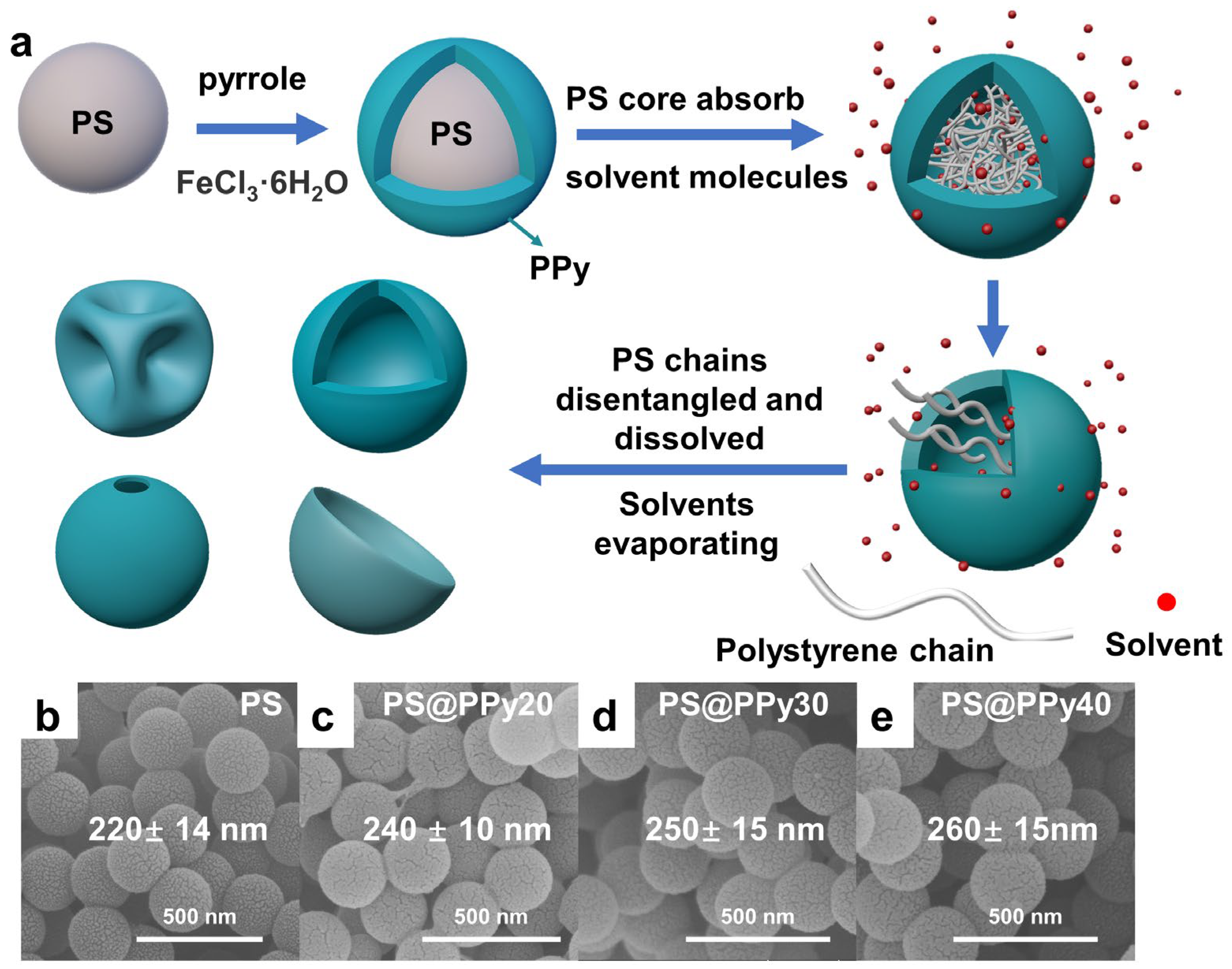
Figure 2.
SEM and corresponding TEM images of (a,a’) DMF PS@PPy20, (b,b’) DMF PS@PPy30, and (c,c’) DMF PS@PPy40; (d) FTIR spectra of PS, PPy, PS@PPy, and DMF PS@PPy; TGA traces of PS, PPy, PS@PPy (e), DMF PS@PPy20, DMF PS@PPy30, and DMF PS@PPy40 (f).
Figure 2.
SEM and corresponding TEM images of (a,a’) DMF PS@PPy20, (b,b’) DMF PS@PPy30, and (c,c’) DMF PS@PPy40; (d) FTIR spectra of PS, PPy, PS@PPy, and DMF PS@PPy; TGA traces of PS, PPy, PS@PPy (e), DMF PS@PPy20, DMF PS@PPy30, and DMF PS@PPy40 (f).

Figure 3.
XPS spectra of (a) PS@PPy30, (b) DMF PS@PPy20, and (c) DMF PS@PPy30. N1s spectra of (d) PS@PPy30, (e) DMF PS@PPy20, and (f) DMF PS@PPy30.
Figure 3.
XPS spectra of (a) PS@PPy30, (b) DMF PS@PPy20, and (c) DMF PS@PPy30. N1s spectra of (d) PS@PPy30, (e) DMF PS@PPy20, and (f) DMF PS@PPy30.

Figure 4.
Capacitive performance of the organic solvent−treated PS@PPy20/30/40 electrodes. (a–c) CV curves at a scan rate of 100 mV s−1; (d–f) GCD curve at a current density of 1 A g−1; (g–i) specific capacitance changes with different current densities.
Figure 4.
Capacitive performance of the organic solvent−treated PS@PPy20/30/40 electrodes. (a–c) CV curves at a scan rate of 100 mV s−1; (d–f) GCD curve at a current density of 1 A g−1; (g–i) specific capacitance changes with different current densities.

Figure 5.
Nyquist plots of DMF PS@PPy (a–c). The insets show the equivalent circuit. Tapping density of organic solvent−-treated PS@PPy20 (d), PS@PPy30 (e), and PS@PPy40 (f). Volumetric capacity of organic solvent-treated PS@PPy20 (g), PS@PPy30 (h), and PS@PPy40 (i).
Figure 5.
Nyquist plots of DMF PS@PPy (a–c). The insets show the equivalent circuit. Tapping density of organic solvent−-treated PS@PPy20 (d), PS@PPy30 (e), and PS@PPy40 (f). Volumetric capacity of organic solvent-treated PS@PPy20 (g), PS@PPy30 (h), and PS@PPy40 (i).

Figure 6.
(a) Linear relationship between the logarithm of the peak current and the logarithm of the scan rate for the PPy−-based electrode. Capacity contribution of PS@PPy20 (b,c), PS@PPy30 (d,g), DMF PS@PPy20 (e,h), and DMF PS@PPy30 (f,i) at different scan rates.
Figure 6.
(a) Linear relationship between the logarithm of the peak current and the logarithm of the scan rate for the PPy−-based electrode. Capacity contribution of PS@PPy20 (b,c), PS@PPy30 (d,g), DMF PS@PPy20 (e,h), and DMF PS@PPy30 (f,i) at different scan rates.

Figure 7.
CV (a), GCD (b), and Nyquist (c) plots of DMF PS@PPy−-based flexible supercapacitors. (d) Ragone plots of DMF PS@PPy20 and the values of recently reported PPy or PPy-based composites for comparison. (e) GCD curves of one, two, and three supercapacitors connected in series at 1 A/g. (f) DMF PS@PPy20 capacitive device diagram.


Table 1.
Solvent parameters and corresponding morphologies of hollow PPy nanoparticles.
| Solvent | Polarity | Solubility Parameter cal0.5 cm−1.5 | Boiling Point (°C) | Vapor Pressure (kPa) | Morphology (PS@PPy20) | Morphology (PS@PPy30) | Morphology (PS@PPy40) |
|---|---|---|---|---|---|---|---|
| Cyclohexane | 0.1 | 7.3 | 80.7 | 13.33 | intact | intact | intact |
| Toluene | 2.4 | 8.9 | 110.6 | 4.00 | collapsed | buckling | intact |
| Tetrahydrofuran | 4.2 | 9.5 | 66.0 | 23.46 | collapsed | buckling | intact |
| Chloroform | 4.4 | 9.21 | 61.2 | 26.45 | collapsed | buckling | buckling |
| Acetone | 5.4 | 9.8 | 56.5 | 30.56 | intact | hollow | buckling |
| N,N-dimethylformamide | 6.4 | 12.1 | 153.0 | 0.50 | buckling | hollow | intact |
Table 2.
Elemental content and surface composition of nitrogen.
| C | N | O | Cl | -NH- | -NH+- | -NH= | |
|---|---|---|---|---|---|---|---|
| PS@PPy30 | 71.6% | 15% | 10.9% | 2.5% | 31.5% | 68.5% | / |
| DMF PS@PPy20 | 62% | 6.1% | 27.2% | 4.7% | 67.6% | 25.4% | 7% |
| DMF PS@PPy30 | 59% | 11.5% | 28% | 1.5% | 68% | 28% | 4% |
Disclaimer/Publisher’s Note: The statements, opinions and data contained in all publications are solely those of the individual author(s) and contributor(s) and not of MDPI and/or the editor(s). MDPI and/or the editor(s) disclaim responsibility for any injury to people or property resulting from any ideas, methods, instructions or products referred to in the content. |
© 2024 by the authors. Licensee MDPI, Basel, Switzerland. This article is an open access article distributed under the terms and conditions of the Creative Commons Attribution (CC BY) license (https://creativecommons.org/licenses/by/4.0/).
Share and Cite
MDPI and ACS Style
Hong, R.; Zhao, X.; Lu, R.; You, M.; Chen, X.; Yang, X. Fabrication of Polypyrrole Hollow Nanospheres by Hard-Template Method for Supercapacitor Electrode Material. Molecules 2024, 29, 2331. https://doi.org/10.3390/molecules29102331
AMA Style
Hong R, Zhao X, Lu R, You M, Chen X, Yang X. Fabrication of Polypyrrole Hollow Nanospheres by Hard-Template Method for Supercapacitor Electrode Material. Molecules. 2024; 29(10):2331. https://doi.org/10.3390/molecules29102331
Chicago/Turabian StyleHong, Renzhou, Xijun Zhao, Rongyu Lu, Meng You, Xiaofang Chen, and Xiaoming Yang. 2024. "Fabrication of Polypyrrole Hollow Nanospheres by Hard-Template Method for Supercapacitor Electrode Material" Molecules 29, no. 10: 2331. https://doi.org/10.3390/molecules29102331