
Laboratory Study of Liquid Nitrogen Cryo-Fracturing as an Environmentally Friendly Approach for Coalbed Methane (CBM) Reservoirs
 ,
,
Abstract
:1. Introduction
2. Geological Settings in Karaganda Basin
3. Experimental Procedure
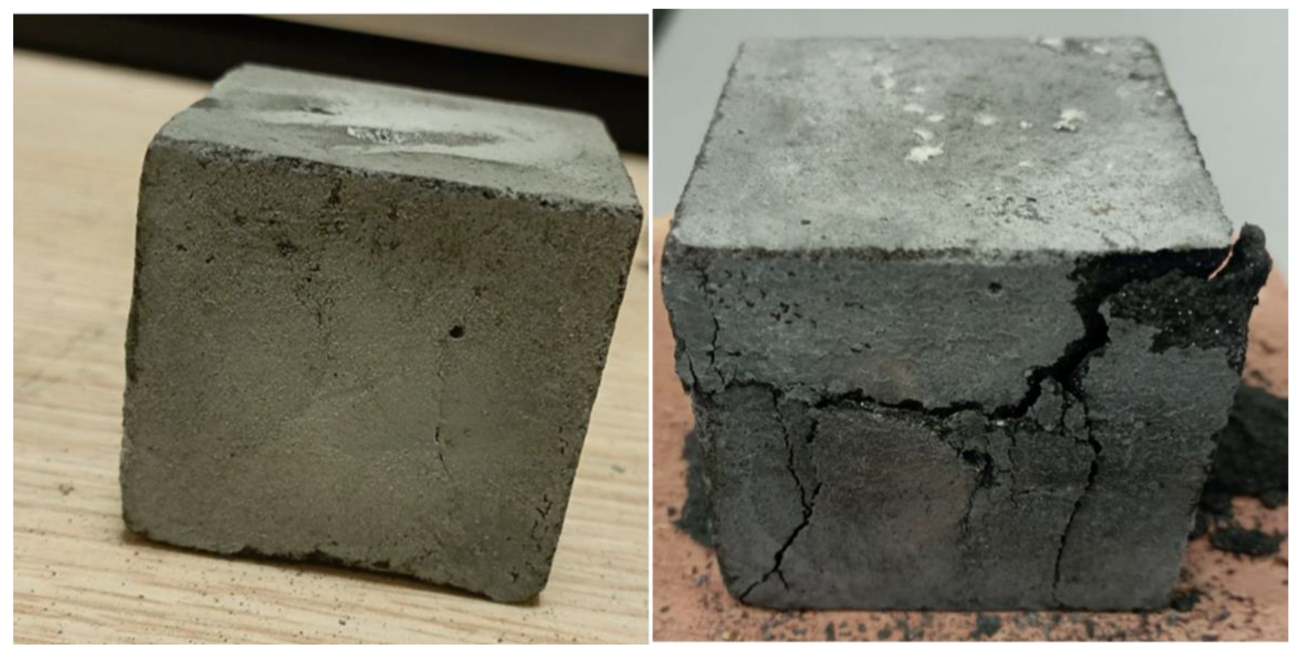
3.1. Synthetic Coal Specimen Preparation
3.2. Test Procedures
4. Results and Discussion
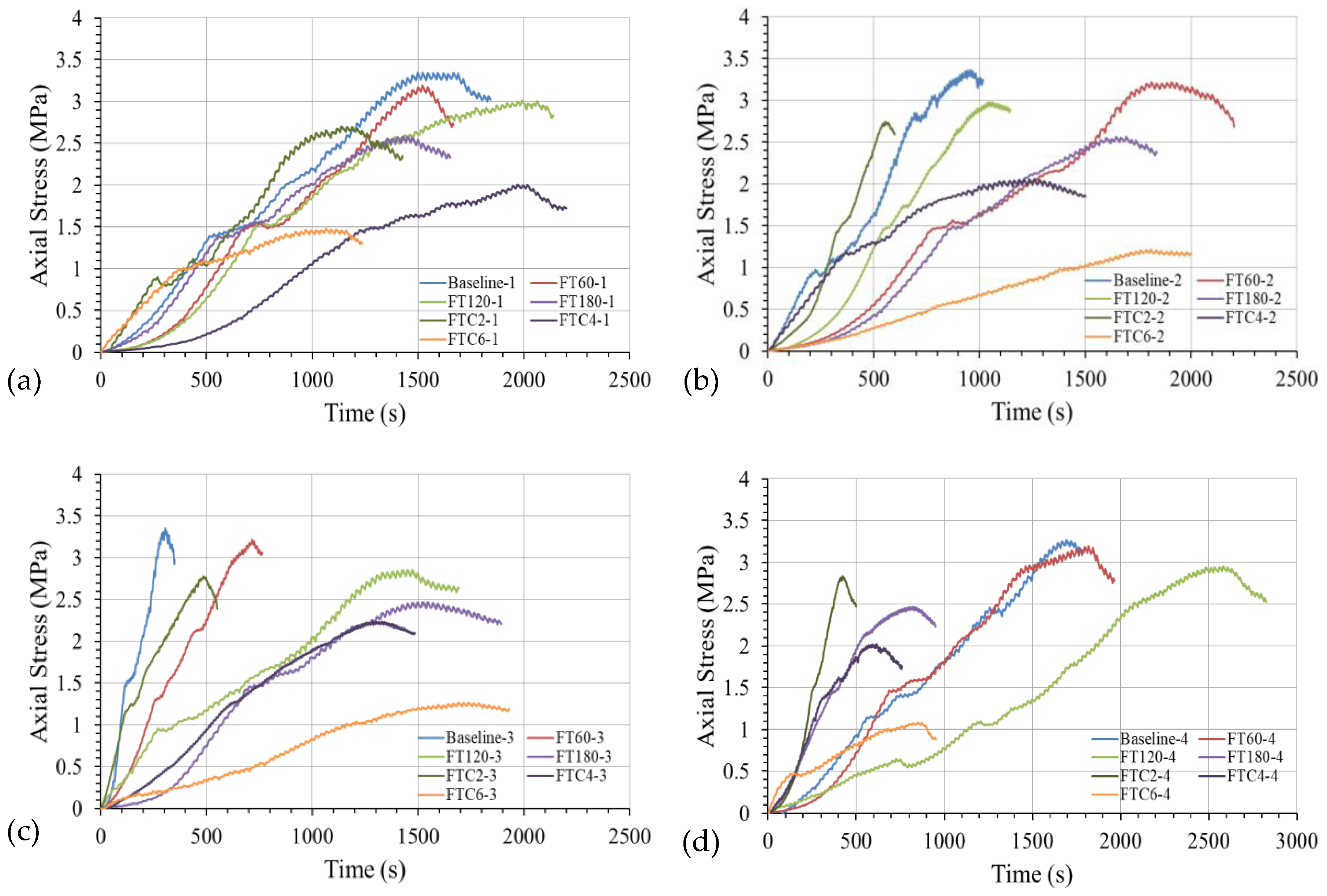
4.1. UCT Outcomes
4.2. Absorbed Energy Outcomes
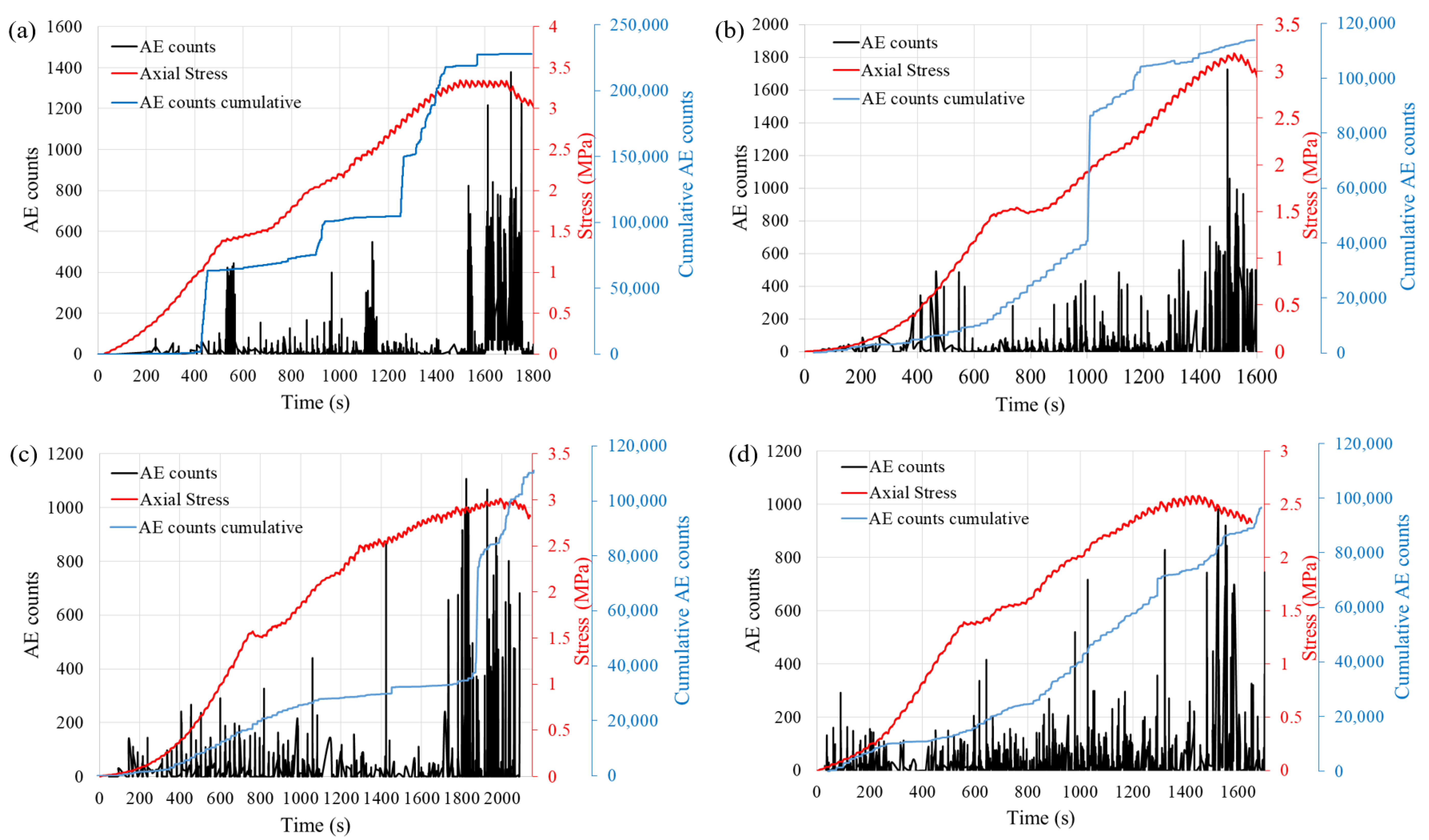
4.3. AE Test Results
4.4. Limitations
- Due to the inability to obtain test samples from the field in the desired and expected shape for material testing, synthetic samples were prepared using common constituents.
- It is assumed that the measures of mechanical stress under compressive load are viable measures of altered sample strength, recognizing that the alteration was a result of thermal stress.
- Testing involving freezing and thawing cycles involved room temperature relaxation, rather than returning to the initial hot sample temperature, as in a downhole stimulation case. Thus, the impact of freezing–thawing cycles is underestimated.
- The exposure to LN2 was by immersion only. In a downhole stimulation case, there would be injection and a combination of mechanical breakdown and thermal shock.
5. Conclusions
- During both freezing time and freezing–thawing cycles, coal specimens exhibit lower peaks in uniaxial compressive strength (UCS) as the time of LN2 treatment increases. The mechanisms leading to mechanical weakening occur at the pore level and involve factors such as grain sorting, pressure, and temperature. However, it remains unclear whether a single mechanism prevails or if multiple mechanisms interact.
- Freezing–thawing specimens indicated lower UCS values compared to freezing time experiments. The damage factor decreases progressively in both freezing–thawing (FT) and freezing–thawing–cooling (FTC) experiments with an increase in the duration of LN2 treatment.
- As the freezing time with liquid nitrogen (LN2) extends, there is an observable rise in both the frequency and amplitude of acoustic emission (AE) signals. The coal samples fractured with LN2 display increased fractures, leading to a sudden surge in AE counts and subsequently larger cumulative AE counts for the samples. Additionally, freezing–thawing (FT) processes show a higher and denser occurrence of signals compared to freezing–thawing–cooling (FTC) processes, indicating a positive correlation with uniaxial compressive strength (UCT) results.
- Analysis of energy absorption demonstrated a clear decrease in the strength of coal samples as freezing time and freezing–thawing cycles increased.
6. Future Research
Author Contributions
Funding
Data Availability Statement
Acknowledgments
Conflicts of Interest
References
- Wang, H.; Asif Amjad, M.; Arshed, N.; Mohamed, A.; Ali, S.; Haider Jafri, M.A.; Khan, Y.A. Fossil energy demand and economic development in BRICS countries. Front. Energy Res. 2022, 10, 842793. [Google Scholar] [CrossRef]
- Brics Energy Research Cooperation Platform. Energy Report. 2020. Available online: https://eng.brics-russia2020.ru/images/114/89/1148985.pdf (accessed on 15 March 2024).
- Abbasi, K.R.; Shahbaz, M.; Zhang, J.; Irfan, M.; Alvarado, R. Analyze the environmental sustainability factors of China: The role of fossil fuel energy and renewable energy. Renew. Energy 2022, 187, 390–402. [Google Scholar] [CrossRef]
- Holechek, J.L.; Geli, H.M.; Sawalhah, M.N.; Valdez, R. A global assessment: Can renewable energy replace fossil fuels by 2050? Sustainability 2022, 14, 4792. [Google Scholar] [CrossRef]
- Ali, K.; Jianguo, D.; Kirikkaleli, D. How do energy resources and financial development cause environmental sustainability? Energy Rep. 2023, 9, 4036–4048. [Google Scholar] [CrossRef]
- Merey, Ş.; Longinos, S. The gas hydrate potential of the Eastern Mediterranean basin. Bull. Miner. Res. Explor. 2019, 160, 117–134. [Google Scholar] [CrossRef]
- Chen, B.; Xiong, R.; Li, H.; Sun, Q.; Yang, J. Pathways for sustainable energy transition. J. Clean. Prod. 2019, 228, 1564–1571. [Google Scholar] [CrossRef]
- Longinos, S.N.; Parlaktuna, M. Examination of methane hydrate formation by the use of dual impeller combinations. React. Kinet. Mech. Catal. 2021, 133, 729–740. [Google Scholar] [CrossRef]
- Tao, Z.; Liu, C.; He, Q.; Chang, H.; Ma, J. Detection and treatment of organic matters in hydraulic fracturing wastewater from shale gas extraction: A critical review. Sci. Total Environ. 2022, 824, 153887. [Google Scholar] [CrossRef] [PubMed]
- Kookana, R.S.; Williams, M.; Gregg, A.; Semmler, A.; Du, J.; Apte, S.C. Sorption, degradation and microbial toxicity of chemicals associated with hydraulic fracturing fluid and produced water in soils. Environ. Pollut. 2022, 309, 119754. [Google Scholar] [CrossRef]
- Patterson, L.A.; Konschnik, K.E.; Wiseman, H.; Fargione, J.; Maloney, K.O.; Kiesecker, J.; Nicot, J.P.; Baruch-Mordo, S.; Entrekin, S.; Trainor, A.; et al. Unconventional oil and gas spills: Risks, mitigation priorities, and state reporting requirements. Environ. Sci. Technol. 2017, 51, 2563–2573. [Google Scholar] [CrossRef]
- Yazdan, M.M.S.; Ahad, M.T.; Jahan, I.; Mazumder, M. Review on the evaluation of the impacts of wastewater disposal in hydraulic fracturing industry in the United States. Technologies 2020, 8, 67. [Google Scholar] [CrossRef]
- Almaliki, A.J.D.; Bashir, M.J.; Llamas Borrajo, J.F. The Impact of Climate Change and Soil Classification on Benzene Concentration in Groundwater Due to Surface Spills of Hydraulic Fracturing Fluids. Water 2022, 14, 1202. [Google Scholar] [CrossRef]
- Seidle, J. Fundamentals of Coalbed Methane Reservoir Engineering; PennWell Corporation: Tulsa, OK, USA, 2011. [Google Scholar]
- Chu, Y.; Zhang, D.; Liu, H.; Wu, X.; Zhai, P.; Sheng, T. Experimental study on mechanical properties, acoustic emission characteristics and energy evolution of coal samples after freezing with liquid nitrogen. Fuel 2022, 321, 123955. [Google Scholar] [CrossRef]
- Longinos, S.N.; Serik, A.; Zhang, D.; Wang, L.; Hazlett, R. Experimental Evaluation of Liquid Nitrogen Fracturing on the Coal Rocks in Karaganda Basin, Kazakhstan. Arab. J. Sci. Eng. 2023, 48, 16623–16638. [Google Scholar] [CrossRef]
- Ali, M.; Shar, A.M.; Mahesar, A.A.; Al-Yaseri, A.; Yekeen, N.; Memon, K.R.; Keshavarz, A.; Hoteit, H. Experimental evaluation of liquid nitrogen fracturing on the development of tight gas carbonate rocks in the Lower Indus Basin, Pakistan. Fuel 2022, 309, 122192. [Google Scholar] [CrossRef]
- Suárez, A.A. The expansion of unconventional production of natural gas (tight gas, gas shale and coal bed methane). In Advances in Natural Gas Technology; IntechOpen: London, UK, 2012; Volume 7. [Google Scholar]
- Teng, T.; Wang, J.G.; Gao, F.; Ju, Y. Complex thermal coal-gas interactions in heat injection enhanced CBM recovery. J. Nat. Gas. Sci. Eng. 2016, 34, 1174–1190. [Google Scholar] [CrossRef]
- Huang, Q.; Liu, S.; Wang, G.; Wu, B.; Yang, Y.; Liu, Y. Gas sorption and diffusion damages by guar-based fracturing fluid for CBM reservoirs. Fuel 2019, 251, 30–44. [Google Scholar] [CrossRef]
- Roy, M.P.; Paswan, R.K.; Sarim, M.D.; Kumar, S.U.R.A.J.; Jha, R.; Singh, P.K. Rock fragmentation by blasting-A review. J. Mines Met. Fuels 2016, 64, 424–431. [Google Scholar]
- Zhang, Z.X. Rock Fracture and Blasting: Theory and Applications; Butterworth-Heinemann: Oxford, UK, 2016. [Google Scholar]
- Al-Bakri, A.; Hefni, M. A review of some nonexplosive alternative methods to conventional rock blasting. Open Geosci. 2021, 13, 431–442. [Google Scholar] [CrossRef]
- Siriwardane, H.J.; Bowes, B.D.; Bromhal, G.S.; Gondle, R.K.; Wells, A.W.; Strazisar, B.R. Modeling of CBM production, CO2 injection, and tracer movement at a field CO2 sequestration site. Int. J. Coal Geol. 2012, 96, 120–136. [Google Scholar] [CrossRef]
- Kumar, H.; Elsworth, D.; Mathews, J.P.; Liu, J.; Pone, D. Effect of CO2 injection on heterogeneously permeable coalbed reservoirs. Fuel 2014, 135, 509–521. [Google Scholar] [CrossRef]
- Yang, X.; Wen, G.; Lu, T.; Wang, B.; Li, X.; Cao, J.; Lv, G.; Yuan, G. Optimization and field application of CO2 gas fracturing technique for enhancing CBM extraction. Nat. Resour. Res. 2020, 29, 1875–1896. [Google Scholar] [CrossRef]
- Lou, Y.; Song, H.; Yang, J.; Huang, X.; Dong, H. Productivity equation of fractured well in CBM reservoirs. J. Nat. Gas Sci. Eng. 2013, 11, 39–45. [Google Scholar] [CrossRef]
- Feng, Q.; Liu, J.; Huang, Z.; Tian, M. Study on the optimization of fracturing parameters and interpretation of CBM fractured wells. J. Nat. Gas Geosci. 2018, 3, 109–117. [Google Scholar] [CrossRef]
- Yang, S.; Cai, Y.; Wei, R.; Zhou, Y. A new fracture permeability model of CBM reservoir with high-dip angle in the southern Junggar Basin, NW China. Energy Explor. Exploit. 2019, 37, 125–143. [Google Scholar] [CrossRef]
- Huang, Q.; Liu, S.; Wang, G.; Wu, B.; Zhang, Y. Coalbed methane reservoir stimulation using guar-based fracturing fluid: A review. J. Nat. Gas Sci. Eng. 2019, 66, 107–125. [Google Scholar] [CrossRef]
- Sun, Z.; Huang, B.; Liu, Y.; Jiang, Y.; Zhang, Z.; Hou, M.; Li, Y. Gas-phase production equation for CBM reservoirs: Interaction between hydraulic fracturing and coal orthotropic feature. J. Pet. Sci. Eng. 2022, 213, 110428. [Google Scholar] [CrossRef]
- Zhao, J.; Liu, P.; Li, J.; Chen, Z.; Li, Y.; Li, F. Fracture propagation induced by hydraulic fracturing using microseismic monitoring technology: Field test in CBM wells in Zhengzhuang region, Southern Qinshui Basin, China. Front. Earth Sci. 2023, 11, 1130280. [Google Scholar] [CrossRef]
- Davies, R.; Foulger, G.; Bindley, A.; Styles, P. Induced seismicity and hydraulic fracturing for the recovery of hydrocarbons. Mar. Pet. Geol. 2013, 45, 171–185. [Google Scholar] [CrossRef]
- Rutqvist, J.; Rinaldi, A.P.; Cappa, F.; Moridis, G.J. Modeling of fault reactivation and induced seismicity during hydraulic fracturing of shale-gas reservoirs. J. Pet. Sci. Eng. 2013, 107, 31–44. [Google Scholar] [CrossRef]
- Schultz, R.; Skoumal, R.J.; Brudzinski, M.R.; Eaton, D.; Baptie, B.; Ellsworth, W. Hydraulic fracturing-induced seismicity. Rev. Geophys. 2020, 58, e2019RG000695. [Google Scholar] [CrossRef]
- Atkinson, G.M.; Eaton, D.W.; Igonin, N. Developments in understanding seismicity triggered by hydraulic fracturing. Nat. Rev. Earth Environ. 2020, 1, 264–277. [Google Scholar] [CrossRef]
- Liew, M.S.; Danyaro, K.U.; Zawawi, N.A.W.A. A comprehensive guide to different fracturing technologies: A review. Energies 2020, 13, 3326. [Google Scholar] [CrossRef]
- Yu, H.; Xu, W.; Li, B.; Huang, H.; Micheal, M.; Wang, Q.; Huang, M.; Meng, S.; Liu, H.; Wu, H. Hydraulic fracturing and enhanced recovery in shale reservoirs: Theoretical analysis to engineering applications. Energy Fuels 2023, 37, 9956–9997. [Google Scholar] [CrossRef]
- Farrokhrouz, M.; Akhondzadeh, H.; Yang, Y.; Awan, F.U.R.; Iglauer, S.; Lebedev, M.; Keshavarz, A. Coal cleat network stimulation through a combination of acidizing and liquid nitrogen fracturing. Gas. Sci. Eng. 2024, 205308. [Google Scholar] [CrossRef]
- Akhondzadeh, H.; Keshavarz, A.; AlYaseri, A.Z.; Ali, M.; Awan, F.U.R.; Wang, X.; Yang, Y.; Iglauer, S.; Lebedev, M. Pore-scale analysis of coal cleat network evolution through liquid nitrogen treatment: A Micro-Computed Tomography investigation. Int. J. Coal Geol. 2020, 219, 103370. [Google Scholar] [CrossRef]
- Memon, K.R.; Mahesar, A.A.; Ali, M.; Tunio, A.H.; Mohanty, U.S.; Akhondzadeh, H.; Awan, F.U.R.; Iglauer, S.; Keshavarz, A. Influence of cryogenic liquid nitrogen on petrophysical characteristics of mancos shale: An experimental investigation. Energy Fuels 2020, 34, 2160–2168. [Google Scholar] [CrossRef]
- Qin, L.; Zhai, C.; Liu, S.; Xu, J.; Yu, G.; Sun, Y. Changes in the petrophysical properties of coal subjected to liquid nitrogen freeze-thaw–a nuclear magnetic resonance investigation. Fuel 2017, 194, 102–114. [Google Scholar] [CrossRef]
- Wang, S.; Su, S.; Wang, D.; Hou, P.; Xue, Y.; Liang, X.; Cai, C.; Gao, X.; Jin, Y.; Yang, S. Experimental study on fracture characteristics of coal due to liquid nitrogen fracturing. Geomech. Energy Environ. 2023, 33, 100438. [Google Scholar] [CrossRef]
- Hou, P.; Su, S.; Gao, F.; Liang, X.; Wang, S.; Gao, Y.; Cai, C. Influence of liquid nitrogen cooling state on mechanical properties and fracture characteristics of coal. Rock Mech. Rock Eng. 2022, 55, 3817–3836. [Google Scholar] [CrossRef]
- Yuan, Y.; Cai, F.; Yang, L. Pore structure characteristics and fractal structure evaluation of medium-and high-rank coal. Energy Explor. Exploit. 2022, 40, 328–342. [Google Scholar] [CrossRef]
- Wu, X.; Li, H.; Lu, J.; Lu, Y.; Hong, Y.; Zheng, C.; Liu, M.; Lin, B.; Shi, S.; Wang, Z. Investigation of cross-scale characterization of porous structure and fluid index in bituminous coal via microwave-LN2 freeze-thaw cycles. Fuel 2024, 357, 129701. [Google Scholar] [CrossRef]
- Zhai, C.; Qin, L.; Liu, S.; Xu, J.; Tang, Z.; Wu, S. Pore structure in coal: Pore evolution after cryogenic freezing with cyclic liquid nitrogen injection and its implication on coalbed methane extraction. Energy Fuels 2016, 30, 6009–6020. [Google Scholar] [CrossRef]
- Longinos, S.N.; Dillinger, A.; Wang, L.; Hazlett, R. Uniaxial compressive strength (UCS) and SEM study of liquid nitrogen for waterless hydraulic fracturing in coalbed methane reservoirs of Karaganda Basin in Kazakhstan. Gas Sci. Eng. 2023, 115, 204998. [Google Scholar] [CrossRef]
- Longinos, S.N.; Wang, L.; Hazlett, R. Advances in cryogenic fracturing of coal-bed methane reservoirs with LN2. Energies 2022, 15, 9464. [Google Scholar] [CrossRef]
- Longinos, S.N.; Abbas, A.H.; Bolatov, A.; Skrzypacz, P.; Hazlett, R. Application of Image Processing in Evaluation of Hydraulic Fracturing with Liquid Nitrogen: A Case Study of Coal Samples from Karaganda Basin. Appl. Sci. 2023, 13, 7861. [Google Scholar] [CrossRef]
- Li, B.; Zong, C.; Huang, L.; Ren, Y.; Lv, X. Study on the influence of liquid nitrogen cold soaking on the temperature variations and seepage characteristics of coal samples with different moisture contents. Geofluids 2021, 2021, 8924016. [Google Scholar] [CrossRef]
- Li, B.; Huang, L.; Lv, X.; Ren, Y. Study on temperature variation and pore structure evolution within coal under the effect of liquid nitrogen mass transfer. ACS Omega 2021, 6, 19685–19694. [Google Scholar] [CrossRef] [PubMed]
- Li, B.; Shi, Z.; Wang, Z.; Huang, L. Effect of liquid nitrogen freeze–thaw cycles on pore structure development and mechanical properties of coal. ACS Omega 2022, 7, 5206–5216. [Google Scholar] [CrossRef]
- Cai, C.; Li, G.; Huang, Z.; Shen, Z.; Tian, S.; Wei, J. Experimental study of the effect of liquid nitrogen cooling on rock pore structure. J. Nat. Gas Sci. Eng. 2014, 21, 507–517. [Google Scholar] [CrossRef]
- Cai, C.; Li, G.; Huang, Z.; Shen, Z.; Tian, S. Rock pore structure damage due to freeze during liquid nitrogen fracturing. Arab. J. Sci. Eng. 2014, 39, 9249–9257. [Google Scholar] [CrossRef]
- Cai, C.; Li, G.; Huang, Z.; Tian, S.; Shen, Z.; Fu, X. Experiment of coal damage due to super-cooling with liquid nitrogen. J. Nat. Gas Sci. Eng. 2015, 22, 42–48. [Google Scholar] [CrossRef]
- Qin, L.; Zhai, C.; Liu, S.; Xu, J. Factors controlling the mechanical properties degradation and permeability of coal subjected to liquid nitrogen freeze-thaw. Sci. Rep. 2017, 7, 3675. [Google Scholar] [CrossRef] [PubMed]
- Qin, L.; Li, S.; Zhai, C.; Lin, H.; Zhao, P.; Shi, Y.; Bai, Y. Changes in the pore structure of lignite after repeated cycles of liquid nitrogen freezing as determined by nitrogen adsorption and mercury intrusion. Fuel 2020, 267, 117214. [Google Scholar] [CrossRef]
- Sandström, T.; Fridh, K.; Emborg, M.; Hassanzadeh, M. The influence of temperature on water absorption in concrete during freezing. Nord. Concr. Res. 2012, 45, 45–58. [Google Scholar]
- Han, S.; Cheng, Y.; Gao, Q.; Yan, C.; Han, Z. Experimental study of the effect of liquid nitrogen pretreatment on shale fracability. J. Nat. Gas Sci. Eng. 2018, 60, 11–23. [Google Scholar] [CrossRef]
- Qu, H.; Li, C.; Qi, C.; Chen, X.; Xu, Y.; Jun, H.; Wu, X. Effect of liquid nitrogen freezing on the mechanical strength and fracture morphology in a deep shale gas reservoir. Rock Mech. Rock Eng. 2022, 55, 7715–7730. [Google Scholar] [CrossRef]
- Mahesar, A.A.; Shar, A.M.; Ali, M.; Tunio, A.H.; Uqailli, M.A.; Mohanty, U.S.; Akhondza-deh, H.; Iglauer, S.; Keshavarz, A. Morphological and petro physical estimation of eocene tight carbonate formation cracking by cryogenic liquid nitrogen; a case study of Lower Indus basin, Pakistan. J. Pet. Sci. Eng. 2020, 192, 107318. [Google Scholar] [CrossRef]
- Mahesar, A.A.; Ali, M.; Shar, A.M.; Memon, K.R.; Mohanty, U.S.; Akhondzadeh, H.; Tunio, A.H.; Iglauer, S.; Keshavarz, A. Effect of cryogenic liquid nitrogen on the morpho-logical and petrophysical characteristics of tight gas sandstone rocks from kirthar fold belt, Indus Basin, Pakistan. Energy Fuels 2020, 34, 14548–14559. [Google Scholar] [CrossRef]
- Hong, C.; Yang, R.; Huang, Z.; Qin, X.; Wen, H.; Cong, R.; Liu, W.; Chen, J. Fracture initiation and morphology of tight sandstone by liquid nitrogen fracturing. Rock Mech. Rock Eng. 2022, 55, 1285–1301. [Google Scholar] [CrossRef]
- Rong, G.; Sha, S.; Li, B.; Chen, Z.; Zhang, Z. Experimental investigation on physical and mechanical properties of granite subjected to cyclic heating and liquid nitrogen cooling. Rock Mech. Rock Eng. 2021, 54, 2383–2403. [Google Scholar] [CrossRef]
- Longinos, S.N.; Hazlett, R. Cryogenic fracturing using liquid nitrogen on granite at elevated temperatures: A case study for enhanced geothermal systems in Kazakhstan. Sci. Rep. 2024, 14, 160. [Google Scholar] [CrossRef] [PubMed]
- Longinos, S.N.; Tuleugaliyev, M.; Hazlett, R. Influence of subsurface temperature on cryogenic fracturing efficacy of granite rocks from Kazakhstan. Geothermics 2024, 118, 102919. [Google Scholar] [CrossRef]
- Ivakhnenko, O.; Aimukhan, A.; Kenshimova, A.; Mullagaliyev, F.; Akbarov, E.; Mullagaliyeva, L.; Kabirova, S.; Almukhametov, A. Advances in coalbed methane reservoirs integrated characterization and hydraulic fracturing for improved gas recovery in Karaganda Coal Basin, Kazakhstan. Energy Procedia 2017, 125, 477–485. [Google Scholar] [CrossRef]
- Sadykov, R.M.; Korobkin, V.V. Geological input data analysis for basin modeling of the south part of Karagandy coal deposit. News Natl. Acad. Sci. Repub. Kazakhstan Ser. Geol. Tech. Sci. 2019, 1, 133–142. [Google Scholar]
- Château, C.; Fustic, M.; Duisekova, M. Geological carbon storage potential of Karagandy Basin, Kazakhstan. Abstract. In Proceedings of the 2nd EAGE Geoscience and Engineering for the Energy Transition Conference, Online, 23–25 November 2021; p. 5. [Google Scholar]
- Kler, V.R. Geology of the Karaganda Coal Basin; Nedra. Geology of Coal and Oil Shale of the USSR: Moscow, Russia, 1973; Volume 9. [Google Scholar]
- Kushev, G.L. Karagandinskii Uglenosnyi Bassein 1963, 2nd ed.; Alma-AtaMinistry of Industry and New Technologies of RoK. 2009: Innovative investment project "Methane" for 2010–2014; Ministry of Industry and New Technologies of RoK: Astana, Kazakhstan, 2009. (In Russian)
- Azizov, T.M.; Vlasov, Y.I. Coal and oil shale basins and deposits of Kazakhstan. A.B. Bekturov Institute of Chemical Sciences JSC: Almaty, Kazakhstan, 2013; pp. 6–106. [Google Scholar]
- Sabitova, D.K. Exploration potential of coalbed methane in Karaganda field. Mod. Appl. Sci. 2015, 9, 145. [Google Scholar] [CrossRef]
- Imanbaeva, S.B. Influences of Geological and Mining Conditions of the D6 Coal Seam and Its Methane Concentration on the Efficiency of Rocks. Ph.D. Dissertation, Karagandy Technical University named after Abylqas Saginov, Karagandy, Kazakhstan, 2022. 163pyes (In Russian). [Google Scholar]
- Tickner, J.; Roach, G. Characterisation of coal and minerals using compton profile analysis. Nucl. Instrum. Methods Phys. Res. 2004, 213, 507–510. [Google Scholar] [CrossRef]
- Bo, L.; He, Q.; Jiang, Z.; Xu, R.; Hu, B. Relationship between coal ash composition and ash fu-sion temperatures. Fuel 2013, 105, 293–300. [Google Scholar]
- Su, X.; Wang, Q.; Song, J.; Chen, P.; Yao, S.; Hong, J.; Zhou, F. Experimental study of water blocking damage on coal. J. Petrol. Sci. Eng. 2017, 156, 654–661. [Google Scholar] [CrossRef]
- Wang, L. Clay stabilization in sandstone reservoirs and the perspectives for shale reservoirs. Adv. Colloid. Interface Sci. 2020, 276, 102087. [Google Scholar] [CrossRef]
- Qin, L.; Zhai, C.; Liu, S.; Xu, J. Mechanical behavior and fracture spatial propagation of coal injected with liquid nitrogen under triaxial stress applied for coalbed methane recovery. Eng. Geol. 2018, 233, 1–10. [Google Scholar] [CrossRef]
- Yang, R.; Hong, C.; Huang, Z.; Wen, H.; Li, X.; Huang, P.; Liu, W.; Chen, J. Liq-uid nitrogen fracturing in boreholes under true triaxial stresses: Laboratory investigation on fractures initiation and morphology. SPE J. 2021, 26, 135–154. [Google Scholar] [CrossRef]
- Zhao, X.; Wang, L.; Yao, B.; Cha, M.; Wu, Y.S. Cryogenic fracturing of syn-thetic coal specimens under true-triaxial loadings-An experimental study. Fuel 2022, 324, 124530. [Google Scholar] [CrossRef]
- Sass, O. Rock moisture fluctuations during freeze-thaw cycles: Preliminary results from electrical resistivity measurements. Polar Geogr. 2004, 28, 13–31. [Google Scholar] [CrossRef]
- Tan, X.; Chen, W.; Liu, H.; Wang, L.; Ma, W.; Chan, A.H.C. A unified model for frost heave pressure in the rock with a penny-shaped fracture during freezing. Cold Reg. Sci. Technol. 2018, 153, 1–9. [Google Scholar] [CrossRef]
- Qin, L.; Zhai, C.; Xu, J.; Liu, S.; Zhong, C.; Yu, G. Evolution of the pore structure in coal subjected to freeze− thaw using liquid nitrogen to enhance coalbed methane extraction. J. Pet. Sci. Eng. 2019, 175, 129–139. [Google Scholar] [CrossRef]
- Qin, L.; Ma, C.; Li, S.; Lin, H.; Ding, Y.; Liu, P.; Wang, P.; Gao, Z. Liquid nitrogen’s effect on the mechanical properties of dried and water-saturated frozen coal. Energy Fuels 2022, 36, 1894–1903. [Google Scholar] [CrossRef]
- Wen, H.; Yang, R.; Huang, Z.; Hu, X.; Hong, C.; Song, G. Flow and heat transfer of nitrogen during liquid nitrogen fracturing in coalbed methane reservoirs. J. Pet. Sci. Eng. 2022, 209, 109900. [Google Scholar] [CrossRef]
- Akhondzadeh, H.; Keshavarz, A.; Awan, F.U.R.; Ali, M.; Al-Yaseri, A.; Liu, C.; Yang, Y.; Iglauer, S.; Gurevich, B.; Lebedev, M. Liquid nitrogen fracturing efficiency as a function of coal rank: A multi-scale tomographic study. J. Nat. Gas Sci. Eng. 2021, 95, 104177. [Google Scholar] [CrossRef]
- Akhondzadeh, H.; Keshavarz, A.; Awan, F.U.R.; Zamani, A.; Iglauer, S.; Lebedev, M. Coal cleat network evolution through liquid nitrogen freeze-thaw cycling. Fuel 2022, 314, 123069. [Google Scholar] [CrossRef]
- Chu, Y.; Zhang, D. Study on the pore evolution law of anthracite coal under liquid nitrogen freeze-thaw cycles based on infrared thermal imaging and nuclear magnetic resonance. Energy Sci. Eng. 2019, 7, 3344–3354. [Google Scholar] [CrossRef]
- Sun, L.; Wu, C.; Teng, T.; Cao, Z.; Liu, F.; Cai, Y.; Xue, Y.; Zhu, Y. Investigation of the impact of heating and liquid nitrogen (LN2) cooling on the mechanical and acoustic emission (AE) properties of coal. Energy Explor. Exploit. 2024. [Google Scholar] [CrossRef]


| Specimen | Process | UCS Peaks (MPa) | Average (MPa) | Difference between Baseline and Experimental Applications | Difference between Successive Experimental Applications | Standard Error (%) | Simple Standard Deviation (%) | Population Standard Deviation (%) | RSD for Simple Standard Deviation | RSD for Population Standard Deviation |
|---|---|---|---|---|---|---|---|---|---|---|
| 1 | Baseline | 3.26 | 3.31 | - | - | 2.28 | 4.95 | 4.29 | 1.49 | 1.29 |
| 2 | 3.36 | |||||||||
| 3 | 3.35 | |||||||||
| 4 | 3.34 | |||||||||
| 1 | FT60 | 3.19 | 3.20 | 3.3 | 3.3 | 0.58 | 1.16 | 1.01 | 0.36 | 0.31 |
| 2 | 3.21 | |||||||||
| 3 | 3.21 | |||||||||
| 4 | 3.19 | |||||||||
| 1 | FT120 | 3.01 | 2.95 | 7.7 | 8.0 | 3.39 | 6.78 | 5.87 | 2.29 | 1.99 |
| 2 | 2.98 | |||||||||
| 3 | 2.85 | |||||||||
| 4 | 2.95 | |||||||||
| 1 | FT180 | 2.46 | 2.52 | 12.9 | 14.5 | 3.03 | 6.07 | 5.26 | 2.40 | 2.08 |
| 2 | 2.56 | |||||||||
| 3 | 2.46 | |||||||||
| 4 | 2.58 | |||||||||
| 1 | FTC2 | 2.74 | 2.76 | 7.4 | 16.6 | 2.84 | 5.68 | 4.92 | 2.05 | 1.77 |
| 2 | 2.71 | |||||||||
| 3 | 2.77 | |||||||||
| 4 | 2.83 | |||||||||
| 1 | FTC4 | 2.01 | 2.06 | 21.0 | 25.2 | 4.09 | 8.18 | 7.08 | 3.95 | 3.42 |
| 2 | 2.05 | |||||||||
| 3 | 2.18 | |||||||||
| 4 | 2.02 | |||||||||
| 1 | FTC6 | 1.21 | 1.27 | 24.0 | 38.5 | 5.35 | 10.69 | 9.26 | 8.40 | 7.27 |
| 2 | 1.42 | |||||||||
| 3 | 1.26 | |||||||||
| 4 | 1.18 |
Disclaimer/Publisher’s Note: The statements, opinions and data contained in all publications are solely those of the individual author(s) and contributor(s) and not of MDPI and/or the editor(s). MDPI and/or the editor(s) disclaim responsibility for any injury to people or property resulting from any ideas, methods, instructions or products referred to in the content. |
© 2024 by the authors. Licensee MDPI, Basel, Switzerland. This article is an open access article distributed under the terms and conditions of the Creative Commons Attribution (CC BY) license (https://creativecommons.org/licenses/by/4.0/).
Share and Cite
Longinos, S.N.; Serik, A.; Bayramov, E.; Junussov, M.; Begaliyev, D.; Hazlett, R. Laboratory Study of Liquid Nitrogen Cryo-Fracturing as an Environmentally Friendly Approach for Coalbed Methane (CBM) Reservoirs. Energies 2024, 17, 2359. https://doi.org/10.3390/en17102359
Longinos SN, Serik A, Bayramov E, Junussov M, Begaliyev D, Hazlett R. Laboratory Study of Liquid Nitrogen Cryo-Fracturing as an Environmentally Friendly Approach for Coalbed Methane (CBM) Reservoirs. Energies. 2024; 17(10):2359. https://doi.org/10.3390/en17102359
Chicago/Turabian StyleLonginos, Sotirios Nik., Alina Serik, Emil Bayramov, Medet Junussov, Dastan Begaliyev, and Randy Hazlett. 2024. "Laboratory Study of Liquid Nitrogen Cryo-Fracturing as an Environmentally Friendly Approach for Coalbed Methane (CBM) Reservoirs" Energies 17, no. 10: 2359. https://doi.org/10.3390/en17102359