Article

Effects of Quasi-Static Strain Rate and Temperature on the Microstructural Features of Post-Processed Microstructures of Laser Powder Bed Fusion Ti6Al4V Alloy

1
Department of Mechanical Engineering, Murang’a University of Technology, Murang’a 10200, Kenya
2
Department of Mechanical and Mechatronics Engineering, Central University of Technology, Bloemfontein 9301, Free State, South Africa
3
Centre for Rapid Prototyping and Manufacturing, Faculty of Engineering, Built Environment and Information Technology, Central University of Technology, Bloemfontein 9301, Free State, South Africa
*
Author to whom correspondence should be addressed.
Appl. Sci. 2024, 14(10), 4261; https://doi.org/10.3390/app14104261
Submission received: 10 April 2024 / Revised: 3 May 2024 / Accepted: 13 May 2024 / Published: 17 May 2024
(This article belongs to the Special Issue Additive Manufacturing and Mechanical Properties of Materials)

Abstract

:
This study documents an investigation of the flow stress properties and microstructural features of Ti6Al4V (ELI) alloy produced using laser powder bed fusion (LPBF). Selected heat treatment strategies were applied to the material to obtain different microstructures. The influence of quasi-static strain rates and temperature on the obtained microstructures of this material and their strain hardening properties are documented in this study. All microstructures of the alloy formed in this study were found to be sensitive to quasi-static strain rates and temperatures, where their flow stresses increased with increasing strain rate and decreased for tests conducted at elevated temperatures. The strain hardening rates of the fine microstructures were found to be high compared to those of coarse microstructures. The strain hardening rates for the various forms of LPBF Ti6Al4V (ELI) examined here were found to diminish with increasing test temperature. Though the deformed surfaces of the built samples were largely dominated by adiabatic shear bands (ASBs), the absence of ASBs was noted for all samples tested at a temperature of 500 °C and an imposed strain of 30%.

1. Introduction

Laser powder bed fusion (LPBF) is an additive manufacturing technique that uses a laser beam to melt and fuse metal powder on a bed in a layer-by-layer process to build three-dimensional (3D) components. The technology is currently being used in the fabrication of components for use in the automobile, aerospace, and biomedical industries [1,2,3]. The use of the technology in these industries is greatly motivated by its flexibility, such as the ability to manufacture parts with intricate and topology-optimized geometry, no tooling requirement, and minimal post-process machining requirements [4]. LPBF is characterized by multiple process parameters such as scanning speed, laser power, hatch-spacing, and laser diameter [5]. These parameters affect the quality and properties of produced parts, such as surface roughness, residual stress, and microstructure [6,7]. The laser energy in LPBF could also engender patterns on the surface of materials which affect their properties such as tribology and biocompatibility [8]. Researchers around the globe have successfully endeavoured to optimize the process parameters of LPBF for fabricating different materials such as titanium-based alloys, steel alloys, and aluminium-based alloys [9,10,11]. In fact, Electro Optical Systems (EOS) offers a range of validated processes parameters for steel, titanium-based, and aluminium-based alloys that are optimal in order to ensure that the properties of the additively manufactured parts are consistently achieved with minimal defects [12].
The most commonly produced and investigated LPBF material is the Ti6Al4V alloy due to its vast light-weighting applications in the aerospace and biomedical industries [13,14]. Due to the versatile nature of AM, biomedical implants and devices can be manufactured from different materials, tailored to the needs of individual patients and medical conditions [3]. Because of this, research centres around the globe, such as the Centre for Rapid Prototyping and Manufacturing (CRPM) of Central University of Technology, Free State, have successfully been established for the additive manufacturing of biomedical implants and devices [15]. The use of AM-produced parts in the aerospace sector is more challenging due to the stringent safety requirements in the sector [2].
The production of the Ti6Al4V(ELI) alloy via AM is attributed to the strong business case that it can be developed for complex and low production volumes of its parts with less wastage of raw material [13]. The as-fabricated LPBF Ti6Al4V alloy is characterized by a non-equilibrium microstructure consisting of columnar prior-β grains filled with a hierarchical structure of acicular martensitic structure [14,16]. The martensitic structure is considered as a hierarchical one, as primary, secondary, tertiary, and quartic α՛ martensite laths are formed within columnar prior β-grains [17]. Moreover, steep temperature gradients develop during the LPBF process due to localized heating and cooling. This causes differential expansion and contraction in different locations of the produced components [18], subsequently generating stresses and strains that remain in the parts as tensile residual stresses and strains [19].
The non-equilibrium microstructure of Ti6Al4V (ELI) produced during LPBF exhibits high strength and low ductility [4]. Furthermore, the tensile residual stresses of its parts are detrimental since they contribute to fatigue damage and stress corrosion cracking [20]. These issues limit the usage of as-fabricated LPBF Ti6Al4V in the aircraft industry, which has stringent safety requirements. Consequently, post-process heat treatment is employed on LPBF parts for the reduction of residual stresses and, ultimately, the transformation of the non-equilibrium microstructure to a ductile and stable α + β microstructure. Various heat treatment strategies have been investigated and have resulted in various microstructures of this alloy that have a wide range of mechanical properties [21,22,23]. Besides affecting the volume fraction of α- and β-phases in the alloy, the heat treatment conditions used also affect the crystallographic texture of these phases, since the α-phase usually precipitates from the β-phase [21]. The heat-treated microstructure of LPBF Ti6Al4V (ELI) typically consists of α + β dual phases, containing numerous lamellar colonies or basket-weave arrangements of alternating layers of α-laths and thin layers of retained β [23].
The mechanical properties of a material at a wide range of strain rates and temperatures for use in structural applications in the aircraft and automotive sectors are of considerable interest. The landing gear beams in aircraft are expected to absorb shock loads during landing [24]. Fan blade-out events in aero-engines, which are a result of the release of high-speed blade fragments, can generate extremely high energy, which may lead to severe damage to components of the engine [25]. Therefore, the design of the containment capacity of aero-engines is important to avoid their penetration by detached blades that may lead to the damage of the fuselage and thus catastrophic losses [26,27]. Furthermore, the inlet part of the turbine engine (fan low- and intermediate-pressure compressors) is exposed to temperatures in the range of 50 °C to 300 °C [28]. The foregoing discussion warrants the investigation of the effect of strain rate and temperature on the properties of materials used in the manufacture of aero-engines. An increased strain rate has been shown to increase the yield stress and subsequent flow stress of a material due to the rapid pile-up of dislocations [29,30]. On the other hand, yield stress and flow stress are known to decrease with an increase in temperature [31,32].
The flow stress properties of wrought Ti6Al4V (ELI) for a wide range of strain rates and temperatures have been widely investigated [31,32,33]. The results of these studies showed that the flow stress properties of wrought Ti6Al4V are strongly dependent on both temperature and deformation rate, with the effect of temperature being insignificant for temperatures above 980 °C [32,33]. Recent research by Woo et al. [30] has focused on the high strain rate and temperature properties of additively manufactured Ti6Al4V. In this work, Woo et al. [34] studied the mechanical properties of Ti6Al4V produced using laser deposition additive manufacturing (LDAM) over the strain rate range of 10−3 s−2 to 103 s−2. The results in [34] showed that LDAM Ti6Al4V had better stability at high strain rates compared to the wrought alloy. The high strain rate properties of various forms of LPBF Ti6Al4V (ELI) were documented in the authors’ previous work in [35]. The strain rate sensitivity of LPBF Ti6Al4V (ELI) in this study was shown to be dependent on grain size and crystallographic texture. The compressive dynamic behaviour of electron beam melting (EBM) Ti6Al4V parts was documented in [36], with results which showed that the yield and compressive strength were significantly higher for tests conducted at a high strain rate as compared to those conducted at quasi-static compression. The thermomechanical properties of the Ti6Al4V alloy manufactured using 3D laser deposition, exposed to strain rates in the range of 0.001 s−1 to 5000 s−1 and temperatures in the range of 298 K and 1173 K, were investigated in [37], with results similar to those obtained in [36]. These results further showed the material to exhibit negative temperature sensitivity under both compressive and tensile loading conditions. The aforementioned studies are part of the very limited literature available on the thermomechanical properties of different microstructures of the additively manufactured Ti6Al4V alloy.
This study documents an investigation of compressive thermomechanical properties of different forms of post-processed LPBF Ti6Al4V (ELI). The as-fabricated samples were initially stress-relieved to reduce their inherent residual stresses, before being exposed to three different heat treatment processes. The obtained microstructures were studied at the onset, using a scanning electron microscope (SEM). Thereafter, a universal testing machine was used to obtain the quasi-static mechanical properties of these samples at ambient temperature. A Gleeble machine was used to investigate the quasi-static behaviour of the different forms of the material at elevated temperatures.

2. Materials and Methods

2.1. Production, Preparation, and Investigation of Ti6Al4V(ELI) Test Samples with Different Microstructures

The Ti6Al4V(ELI) test samples for use in this study were produced using the direct metal laser sintering (DMLS) process, one of the trademarks of LPBF. An EOSINT M280 DMLS machine from Electro Optical Systems (EOS) GmbH, Krailling, Germany, was used for this work. The raw material for the process was gas-atomized spherical Ti6Al4V(ELI) alloy powder. The elemental chemical composition of this powder can be found in [38]. Cylindrical rods with a length and diameter of 80 mm and 6 mm, respectively, were manufactured. The produced samples while still on the machine-build platform are shown in Figure 1.
The samples shown in Figure 1 were initially stress-relieved to alleviate process-related residual stresses before being subdivided into three groups, designated hereinafter as samples C, D, and E, for further high-temperature heat treatment. It is important to note that sample designations A and B were reserved for as-built and stress-relieved samples, respectively. These two forms of alloy were not exposed to mechanical testing as they are known to exhibit non-equilibrium microstructure and therefore low ductility. [16,17,39]. Stress-relieving and high-temperature heat treatment cycles were conducted in an SS12/24-13 MDX Super SeriesTM vacuum furnace system that has a horizontal vacuum chamber. The stress-relieving heat treatment was conducted at a temperature of 650 °C for a residence time of 3 h, followed by furnace cooling to room temperature. A summary of the high-temperature heat treatment cycles applied to samples C, D, and E is shown in Table 1. Controlled cooling rates were achieved by regulating the rate of flow of a stream of argon gas through the furnace chamber. This was done to ensure that there was sufficient grain growth, while minimising the excessive coarsening of the grains formed during cooling.
Small pieces of samples with a height of 12 mm were cut from the middle area of the samples shown in Figure 1, and then sectioned into halves across the diameter, for preliminary microstructural investigation. The sectioning was executed using a wire-cutting electrical discharge machine (EDM). The sectioned pieces were then hot-mounted using Bakelite, with their sectioned surfaces exposed, followed by the chemical and mechanical polishing of the free surfaces, cleaning under tap water, and finally blowing with a strong stream of air. The polished surfaces were then etched using Kroll’s reagent, which consisted of 92 mL of distilled water, 2 mL of hydrofluoric acid, and 6 mL of nitric acid. The microstructures of the LPBF Ti6Al4V(ELI) samples were then investigated using a JEOL JSM-7001F scanning electron microscope (JEOL, Tokyo, Japan). The SEM was also equipped with an electron backscatter diffraction (EBSD) detector, which was used to study the grain misorientation in the three forms of the LPBF Ti6Al4V(ELI) alloy.
The heat-treated cylindrical rods of samples C, D, and E were cut into small compression test samples with a diameter and length of 6 mm and 9 mm, respectively. The end surfaces of these cut compression specimens were then faced off on a lathe machine to ensure perfect contact with the loading cells of the uniaxial testing frame and Gleeble machine during compression testing.

2.2. Low-Strain-Rate Compression Tests at Ambient Temperature

An Instron 1342 servo-hydraulic universal testing machine (UTM) at the Council for Scientific and Industrial Research (CSIR) of South Africa was used to study the low-strain-rate properties of heat-treated microstructures of LPBF Ti6Al4V (ELI). The UTM machine had a calibrated load capacity of up to 50 kN. The machine’s rate control mode was used for uniaxial compression testing to generate different desired strain rates in the gauge sections of the samples. The compression testing of different heat-treated samples of LPBF Ti6Al4V (ELI) at ambient temperature was conducted at the three different strain rates of 0.1 s−1, 0.005 s−1, and 0.001 s−1.

2.3. Low-Strain-Rate Compression Testing at Elevated Temperatures

Uniaxial compression tests at elevated temperatures were conducted using a Gleeble 3800-GTC machine(DSI, New York, NY, USA) at the Centre for Materials Engineering of the University of Cape Town. The machine is equipped with an ISO-TTM anvil, which eliminates the axial gradient of temperature, thus providing a uniform temperature within the entire volume of the specimen during deformation. A thick graphite foil was used as a lubricant in the uniaxial compression testing with ISO-T anvils. Two thermocouples were welded to each test sample, with one at midspan and the other one at the end of the sample. The test specimen was then heated up at a rate of 10 °C/s to the required test temperature and held at that temperature for 60 s before applying load to a predetermined value. The heating profile, as well as the test temperatures and strain rates used in this study, are summarized in Figure 2, in which the symbol RT refers to room temperature. As shown in this figure, the different microstructures of LPBF Ti6Al4V (ELI) were tested at the two elevated temperatures of 200 °C and 500 °C and at the strain rates of 0.1 s−1, 0.005 s−1, and 0.001 s−1, at each of these temperatures. The samples were loaded up to a strain of about 30% to ensure sufficient plastic deformation, while at the same time avoiding damaging the load cells due to the fracture of the test specimens.
A summary of the tests discussed in Section 2.2 and Section 2.3 and the number of test specimens in each case are presented in Table 2 for ease of reference. Where three samples in the same group were tested at the same conditions of temperature and strain rate, the average stress–strain curve was obtained using the data obtained for each sample. The developed Matlab (R2019a) codes presented in Appendix A were applied to obtain the average curve from these data.

3. Results and Discussion

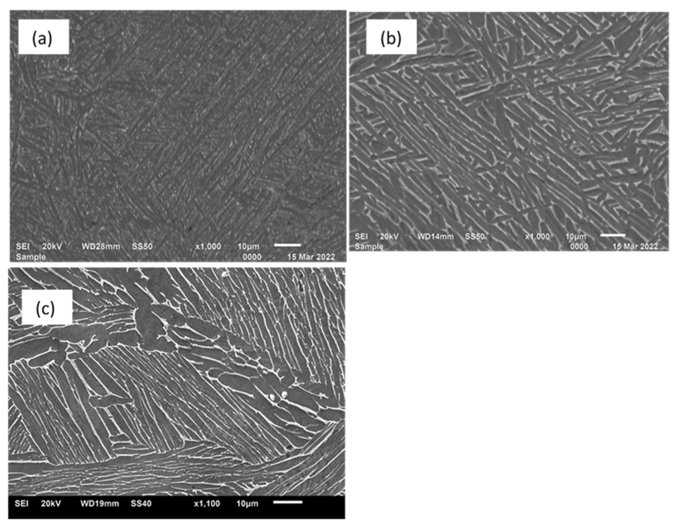
3.1. Microstructures

Figure 3 shows different microstructures of LPBF Ti6Al4V (ELI) obtained after exposing the stress-relieved samples of the alloy to the heat treatment cycles presented in Table 1. The heat-treated microstructures of LPBF Ti6Al4V (ELI) shown in this figure consist of equilibrium mixtures of α and β phases. The α-phase appears as the darker phase while the β-phase is brighter. The heat treatment at 800 °C resulted into the formation of a finer lamellar microstructure where the α-phase appeared in needle-like morphology, as seen in Figure 3a. At higher heat treatment temperatures just below the α→β transformation temperature, the growth of the α-phase is evident in Figure 3b, from which the thickness of the laths is seen to be coarse. Samples E that were heat-treated at a temperature above the α→β transformation temperature was characterized by a typical Widmanstätten microstructure, where colonies consisting of several parallel α-laths were present, as shown in Figure 4c. While the β-grains appeared in small patches and in particle-like morphology in samples C, the β-lamellar grains were clearly visible along the α-laths boundaries in samples C and D. The α-laths in samples C had an average thickness of about 2.5 µm, with lengths extending to over 100 µm. In samples D, the α-laths had an average thickness of 6 µm and lengths of about 150 µm. In Figure 3c the thickness of the α-laths within the colonies were in the range of 7–15 µm, while the average thickness was determined as 9 µm.
The lengths of the α-laths in each colony were limited by the adjacent colonies, as was observed in references [14,15,19,20]. There was also evidence of a globalization of α-grains in some regions, believed to have been initially grain-boundary α-grains in samples E, as shown in Figure 3c.
A statistical analysis of the volume fraction of β-phases present in these three different forms of the alloy was carried out on the surface of the polished samples using the X-ray diffraction method. The obtained results are presented in Figure 4. Different peaks belonging to the α-phase (hcp-titanium) and β-phase (bcc-titanium) were indexed on the three different samples of LPBF Ti6Al4V(ELI), which confirmed the observations made here about the microstructures shown in Figure 3. While the peak reflections in the three different microstructures of the alloy were largely for the α-phase, a peak reflection of the plane at an angle of 2 θ o of the XRD profile was detected in each category of samples. The volume fraction of the β-phase was determined from the relative peak intensities as 3.6%, 6.4%, and 6.6% for samples C, D, and E, respectively.

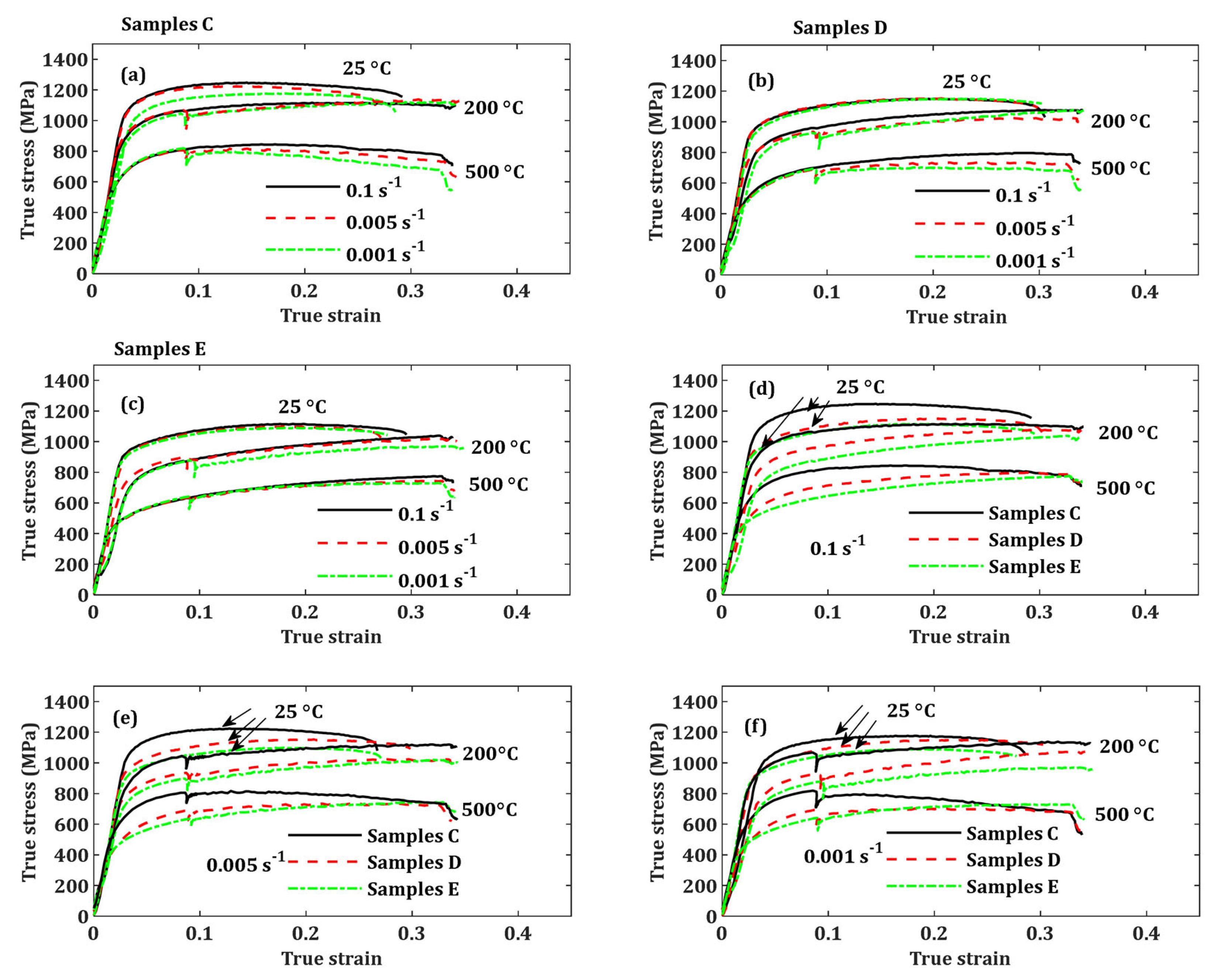
3.2. Flow Properties at Different Strain Rates and Temperatures

Figure 5 shows the flow stress properties of the different microstructures of LPBF Ti6Al4V(ELI) produced here, exposed to different strain rates and temperatures. The curves of flow stress for samples C, D, and E are presented in Figure 5a, Figure 5b, and Figure 5c, respectively. The effects of external state variables are clearly seen in these curves, where, generally, the flow stress increases with increasing strain rate and decreases with increasing test temperature for the three different microstructures of LPBF Ti6Al4V(ELI). The effect of temperature on the flow stress of the alloy is seen in Figure 5a–c to be more significant compared to that of the strain rate. It is also important to note that the compression samples were not loaded to failure in this study to prevent damaging the loading cells, even though the samples were still loaded to allow sufficient plastic deformation. Thus, the ductility of the samples under the compression test carried out in this study at various levels of strain rate and temperature could not be conclusively discussed.
A comparison of the flow stress properties of the three different forms of the alloy produced here is presented in Figure 5d–f at the strain rates of 0.1 s−1, 0.005 s−1, and 0.001 s−1, respectively, and temperatures of 25 °C, 20 °C, and 500 °C, in each case. Generally, samples C recorded the highest values of flow stress at all test strain rates, followed by samples D, while samples E recorded the lowest values. The sharp decline in stress at a strain of approximately 0.1 for some tests conducted at test temperatures of 200 °C and 500 °C was related to Gleeble machine errors and not material properties.
The values of yield (σy) and ultimate compressive (σucs) stresses for these samples at various levels of the two external state variables of strain rate and temperature are presented in Table 3 and their trends are shown in Figure 6. The pronounced effect of temperature on the yield and ultimate compressive stresses is clearly shown in Table 3 and Figure 6, where the increase in temperature leads to a decrease in these two material properties for the three forms of the LPBF Ti6Al4V(ELI) alloy produced here. In contrast, the effect of strain rate on the yield and ultimate compressive stresses of these three forms of the LPBF Ti6Al4V(ELI) alloy is significantly lower. In some cases, especially as the test temperature increases, there is an evident increase in yield and compressive stresses as the strain rate increases (Figure 6). This can be attributed to thermal softening overcoming instantaneous strain hardening and flow stress hardening, as high test temperatures encourage the climbing as well as gliding of dislocations, so that recovery due to the rearrangement of dislocations and the annihilation of dislocation pairs proceeds quickly [35].
Studies have shown that polycrystalline materials exhibit a weak strain rate-dependent response at low strain rates, but this increases at high strain rate regimes (10−2 s−1) [32,40] It has been argued that deformation at low strain rates is controlled by dislocation forests and/or the interaction of dislocations with grain boundaries or precipitates. On the other hand, deformation at high strain rates is attributed to viscous drag forces slowing down the movement of dislocations and increasing plastic strain flow stress, in what is commonly referred to as strain rate hardening [41]. Further details on the strain hardening of different microstructures of LPBF Ti6Al4V(ELI) are covered in Section 3.3.
At a given test condition, the yield stress and compressive stress of samples C are higher than those of samples E and D, while those of samples E are lower than those of samples D, as shown in Figure 5d–f. The yield strength of a material can be decomposed into two components: (a) the thermal part, which is dependent on strain rate and temperature, and (b) the athermal part, which is insensitive to these two factors [32,41,42]. The athermal component of yield stress is normally influenced by long-range obstacles such as far-field dislocation forests and grain boundaries [42]. Furthermore, the influence of grain boundaries on yield stress can be rationalized in terms of the Hall–Petch relationship [43], where small grains result in higher yield stress and vice versa. Moreover, the mechanical properties of titanium alloys with lamellar microstructures such as those presented in Figure 3 are influenced by effective slip length (the shortest distance dislocations can travel before encountering obstacles), which is obviously the thickness of the α-laths. This explains the trends seen in Figure 5 and Table 3 that the yield stress decreased from samples C, with an average grain size of 2.5 µm, through to samples D and E, with average grain sizes of 6 µm and 9 µm, respectively.
Another factor that could support the observation made in Figure 5d–f and Table 3 is the density and misorientation of grain boundaries in samples C, D, and E, shown in Figure 7. A dense large network of grain boundaries, in any order of the samples from the highest to lowest, would suggest an increase in hardness and therefore strength in the same order. The trend of Vickers’s micro-hardness of these samples, in order from the highest to the lowest, was reported in Muiruri et al. [39] for samples C, E, and D. The average initial dislocation densities of these different forms of LPBF Ti6Al4V(ELI) also showed a similar trend, as reported in Muiruri et al. [39].
Grain boundaries, or high-angle grain boundaries (HAGBs), are characterised by high misorientation angles > 15. Misorientation angles less than 15 are commonly used to describe sub-grain boundaries within a given grain and are usually referred to as low-angle grain boundaries (LAGBs). The misorientation of laths that influence the inclination of interfaces between adjacent laths further enhances the strength of parts by hindering the extension of slip across the material. The percentage of sub-grains, or LAGBs, was relatively low in the three forms of the LPBF Ti6Al4V(ELI) alloy, accounting for >0.1%, 2.5%, and 3.7% in samples C, D, and E, respectively. The higher micro-hardness and dislocation density in samples E than in samples D obtained in references [42], as reported in the preceding paragraph, can be attributed to the higher LAGBs in samples E than in samples D. Generally, LAGBs are dislocations in nature, and their increase could possibly lead to an increase in micro-hardness as they offer increased resistance to localized plastic deformation induced by mechanical indentation. The forgoing discussion and the results obtained in Figure 5 suggest that the Hall–Petch effects on the strengthening of a material outweigh those of LAGBs.
A relatively large fraction of the HAGBs had misorientation angles of between 55 ° and 70° in the three cases of samples, as seen in Figure 7. This is not surprising, as eight of the twelve possible α-variants had misorientation between these angles. A large percentage of grains in samples C had a misorientation angle of 65°, while misorientation frequencies in samples D and E peaked at an angle of 60°. This suggests an ease in slip transfer in samples D and E in comparison to samples C, which further confirms the observation of yield stress and flow stress in Figure 5.
Even though the highest peak frequency of misorientation angles for samples E was 53% compared to a value of 37% for samples D, the flow stress curves of samples D at all test conditions were higher than those of samples E. This suggests that the Hall–Petch strengthening mechanism dominates the influence of grain boundary misorientation. The difference in the highest peak frequency of misorientation in samples C, D, and E suggests that microstructural growth and transformation in Ti6Al4V (ELI) are accompanied by the rotation of grains.

3.3. Strain Hardening

Figure 8, Figure 9 and Figure 10 show the effect of microstructure, strain rate, and temperature, respectively, on the strain hardening of the LPBF Ti6Al4V(ELI) alloy. It is important to note that the strain-hardening behaviour of polycrystalline materials involves an intricate interaction of numerous microstructural factors such as grain boundaries, misorientation, and dislocations [44].
Strain hardening is also intrinsically coupled with other aspects such as the development of preferred lattice orientations, the formation of new sub-grains, the annihilation of dislocations, and the formation of local shear zones [45]. All these factors influence the various stages of strain hardening. It is seen in Figure 8, Figure 9 and Figure 10 that the test data for the three different forms of LPBF Ti6Al4V(ELI) show at least two of the three known stages of strain hardening. Stage I exhibits a sharp decline in the rate of strain hardening, which is ascribed to the multiplication of dislocations, with an increase in plastic strain at a decreasing rate and therefore a piling-up of dislocations at grain boundaries, resulting in an increase in flow stress [46,47]. Immediately after this stage, the strain hardening rate decreases to another region with a constant value of strain hardening and is referred to as stage II. The relatively steady state in this region is due to a prevailing balance between the accumulation and annihilation of dislocations. Stage III, which exhibits a sudden decrease in strain hardening, is generally not very clear, especially at tests conducted at elevated temperatures, as the applied loads are normally withdrawn at low strains, probably before the occurrence of the intense localization of shear. The sharp increase and decrease in strain hardening rate observed in these test conditions conducted at elevated temperatures here was probably due to the sudden withdrawal of the deforming force during the test and not the properties of the material. Nevertheless, stage III strain hardening is clearly visible for tests conducted at ambient temperature, as shown in Figure 8a,d,g and Figure 9a,d,g, all at room temperature.
From Figure 8, at all test conditions of temperature and strain rate, the strain hardening rate of samples C in stage I was generally higher than that of samples D and E, except at a temperature of 200 °C and a strain rate of 0.001s−1 (Figure 8f), which can be considered an outlier in this case. These observations are attributed to the fine microstructure and therefore the extended network of grain boundaries in samples C, which would suggest a high rate of accumulation and a pile-up of dislocations. The strain hardening curves of samples D and E are nearly overlapping in stage I, while in stage II, the curves for the three forms of LPBF Ti6Al4V (ELI) are nearly overlapping in most of the testing conditions. In Figure 9a, the strain hardening rate in stage I of samples C at 25 ° C at the lower strain rate of 0.001 s−1 is higher than those of the other two strain rates. The effect seems to diminish at high test temperatures as the strain hardening curves of samples C at different strain rates are overlapping, as seen in Figure 9b,c.
The effects of strain rate on strain hardening for samples D and E were generally insignificant, as in most cases, the curves were overlapping, as seen in Figure 9d–i. At a test temperature of 200 °C for samples D and E, stage I and II strain hardening at the middle strain rate were higher and lower, respectively, than for the other two strain rates. This is likely to have been due to a testing error of the Geeble machine that caused less banding together of the obtained stress–strain curves, as shown in Figure 5b,c.
The influence of temperature on the strain hardening of various microstructures of LPBF Ti6Al4V (ELI) is apparent from Figure 10, where an increase in test temperature generally led to a decrease in the rate of strain hardening. This is anticipated as an increase in temperature enhances the interaction of dislocations and aids in the annihilation of edge and screw dislocations during strain hardening, thus leading to a decrease in the rate of strain hardening.

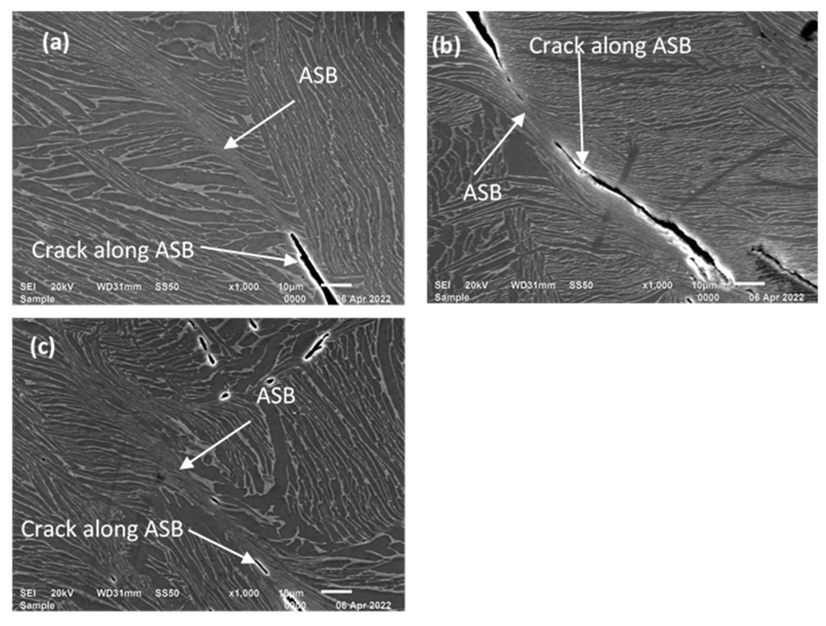
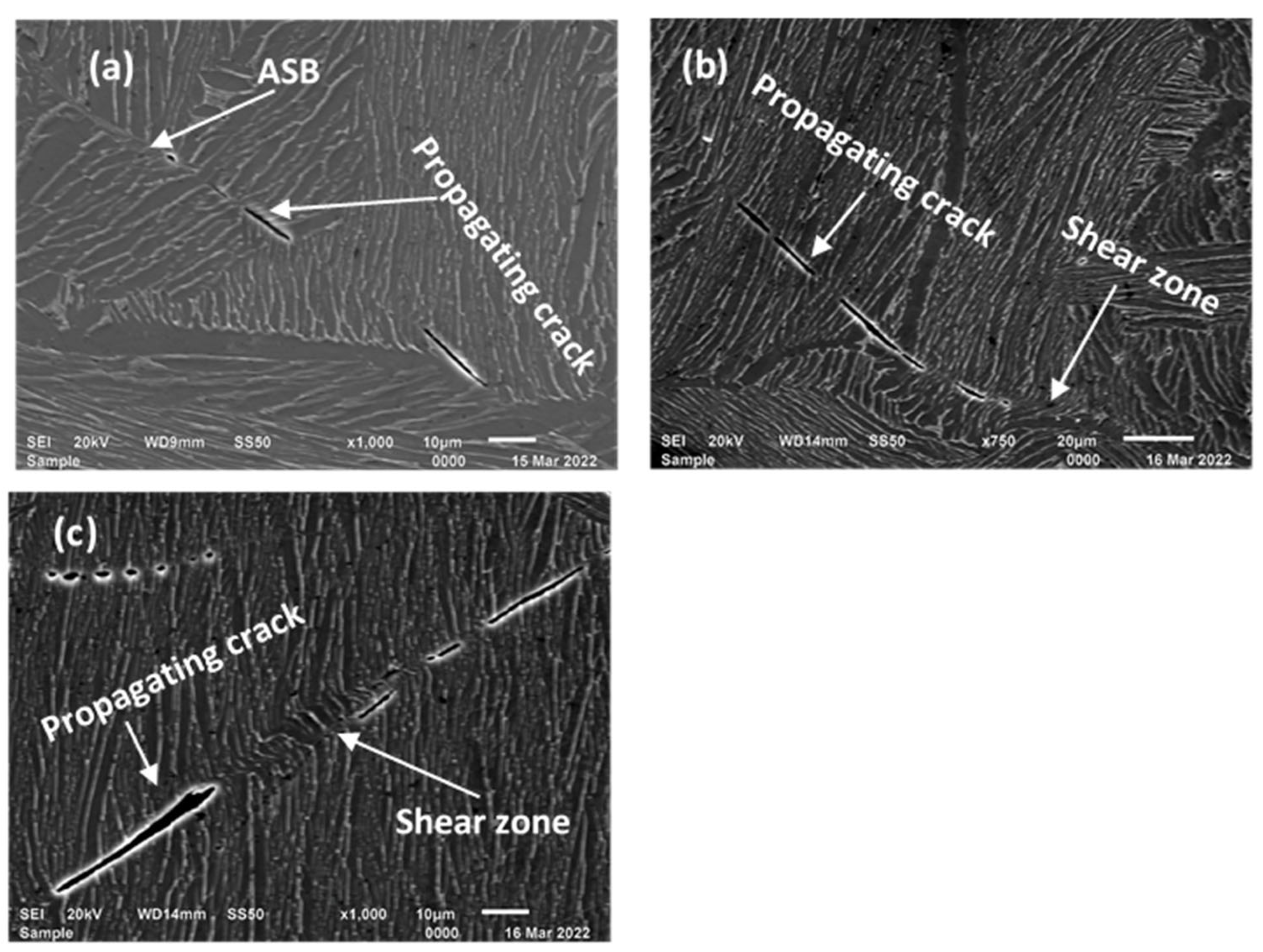
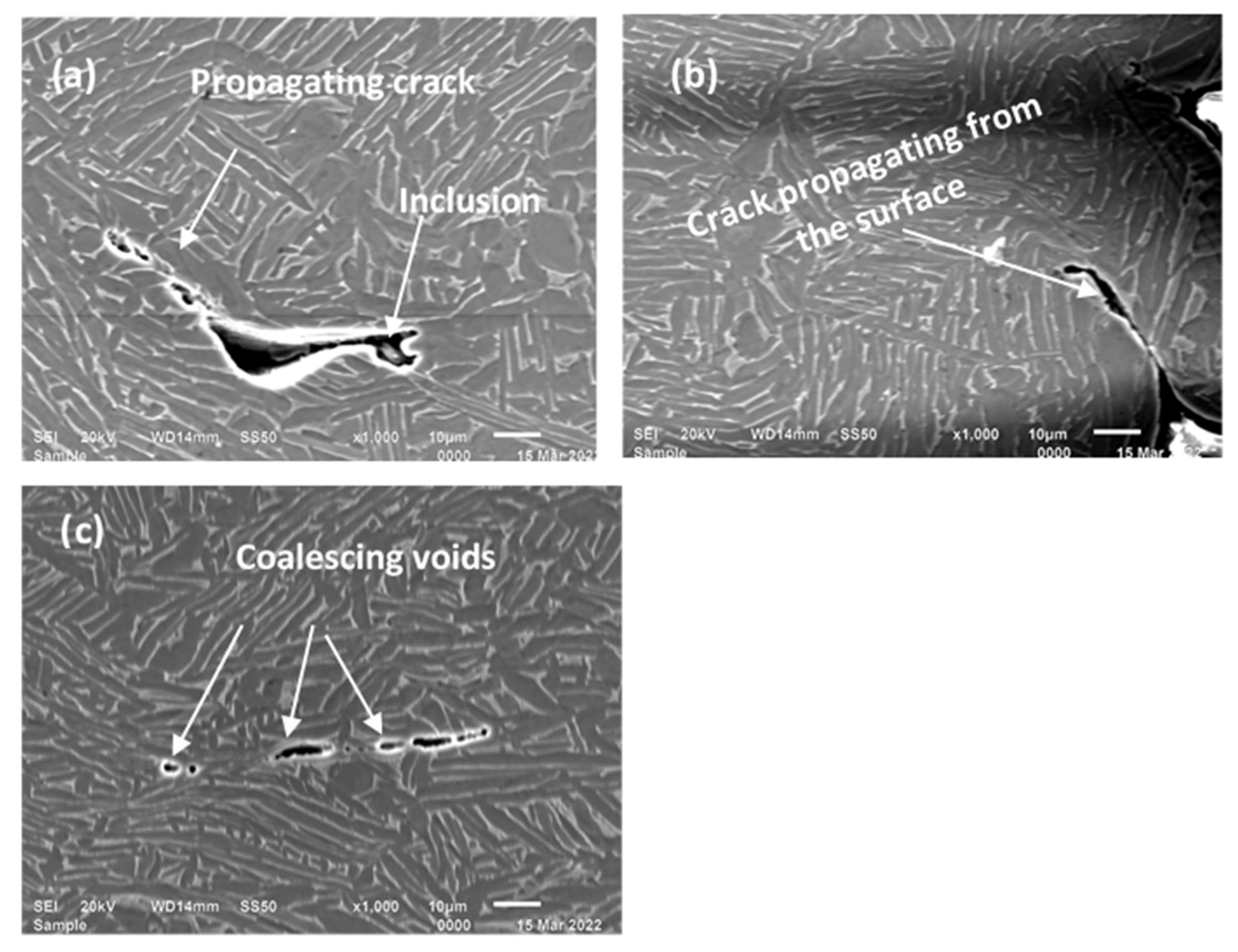
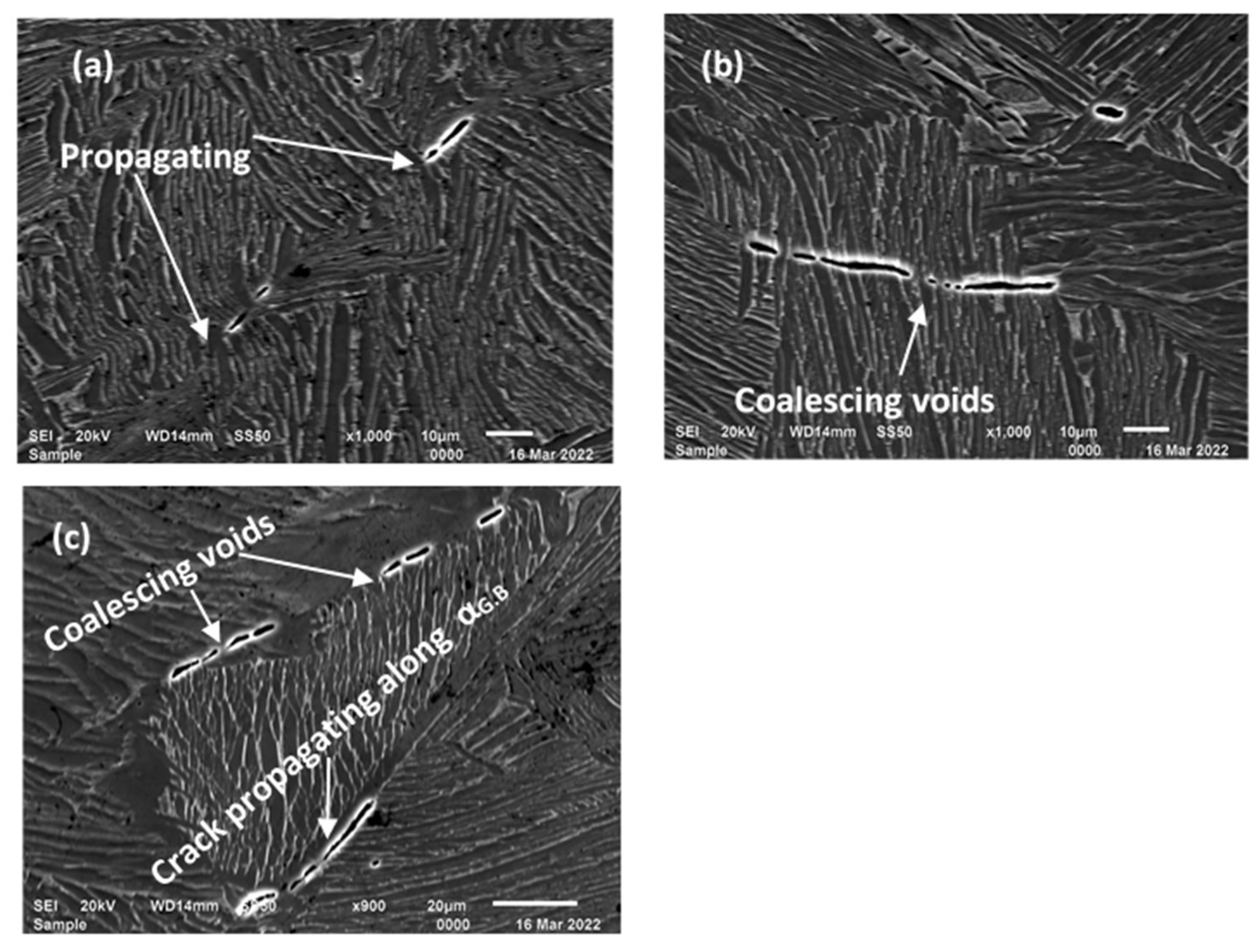
3.4. Analysis of Deformed Surfaces

3.4.1. Deformed Surfaces of Samples Tested at Ambient Temperature (25 °C)

Figure 11, Figure 12 and Figure 13 show the deformation features for samples tested at ambient temperature and at different strain rates. All three different forms of LPBF Ti6Al4V (ELI), deformed at different strain rates, show narrow zones of highly localized deformation commonly known as adiabatic shear bands (ASBs). The formation of ASBs is usually attributed to plastic instability resulting from thermal softening, which overcomes the effect of strain hardening in a deformed region. Plastic instability occurs when the local rate of heat generated due to plastic strain exceeds the rate of heat dissipation to the surrounding material. Plastic instability usually occurs at high strain rates, but it has also been reported to occur at low strain rates in materials with a low strain hardening rate, low strain rate sensitivity, low thermal conductivity, and high thermal softening rate [44]. The Ti6Al4V alloy usually possesses a relatively low strain hardening rate and high strength, as shown in Figure 8, Figure 9 and Figure 10 and Table 3, as well as a low thermal conductivity of about 6.7 W/m.K [45]. Therefore, the alloy is susceptible to failure by adiabatic shear banding, as is shown in Figure 11, Figure 12 and Figure 13.
As seen in these figures, the cracks, whose longer axes are oriented along the longitudinal directions of the respective ASBs, propagate along the longitudinal directions of these ASBs, possibly as a result of the coalescence of voids. The propagation of cracks along the longitudinal directions of the ASBs is expected to cause the final fracture of the samples.

3.4.2. Deformed Surfaces of Samples Tested at 200 °C

Figure 14, Figure 15 and Figure 16 show the deformation features of the three different forms of LPBF Ti6Al4V(ELI) samples tested at a temperature of 200 °C and at strain rates of 0.001 s−1, 0.005 s −1, and 0.1 s−1. The micrographs in Figure 14 show that the failure surfaces of samples C were dominated by the growth and coalescence of microscopic voids and crack propagation. This is an important failure mechanism in ductile materials. Adiabatic shear bands were not apparent in samples C, as shown in this figure, in contrast to what was observed at room temperature. This suggests that the applied strain rates at this strain of about 30% imposed on this material at this temperature were not sufficient to cause the localization of plastic flow.
The presence of ASBs and cracks propagating along them was evident in samples D and E at all testing conditions, as shown in Figure 15 and Figure 16. This is similar to the observation made for the two forms of LPBF Ti6Al4V (ELI) tested at room temperature, as shown in the micrographs in Figure 12 and Figure 13. This suggests that the applied strain rates at this strain of about 30% were sufficient to cause the localization of plastic flow in samples D and E at a temperature of 200 °C. The difference in observations made for samples C and those of samples D and E can be attributed to the material’s hardness.
The difference in the observations made for samples C, and samples D and E can be attributed to the hardness of the different forms of the alloy. Generally, one of the critical factors that influences the presence and thickness of ASBs is the hardness of materials [45], and it is known that the thickness of ASBs diminishes with the increasing hardness of materials. The localization of deformation is enhanced when the resistance to deformation decreases with strain. It is further enhanced by strain rates, weakening regions where stress concentration is high [45,46,47]. Therefore, flow stress localization, which appears in the form of ASBs, may fail to occur in harder materials due to their high resistance to softening and the attendant formation of localized shear bands [47].

3.4.3. Deformed Surfaces of Samples Tested at 500 °C

The absence of ASBs was also noted in samples C tested at a temperature of 500 °C and at different strain rates, as shown in Figure 17, which is similar to the observation made for this material for tests conducted at 200 °C. However, in some cases, for instance, at a strain rate of 0.005 s −1 and (c) 0.1 s−1, cracks initiating from the surface and propagating towards the interior part of the samples were evident. The initiation of cracks from the surface of this material is attributed to the surface roughness of the parts produced, which act as sites of crack initiation and are therefore precursors to the failure of parts.
The absence of ASBs was also noted in samples D tested at a temperature of 500 °C and at different strain rates, as shown in Figure 18. However, deformation in this case was dominated by the growth and coalescence of voids, as well as the propagation of cracks. The absence of ASB for this material at these testing conditions was ascribed to its hardness and testing temperature, suggesting that flow stress localization occurs at strains higher than 30% at a test temperature of 500 °C.
The absence of ASBs was also observed in samples E tested at a temperature of 500 °C and at all test strain rates, as shown in Figure 19. Cracks propagating along the grain boundary α-grains and across the α-colonies characterised the deformation in this material, as shown in Figure 19c.

4. Conclusions

A study of the effects of quasi-static strain rates and temperature on the microstructures of various forms of the Ti6Al4V(ELI) alloy produced using LPBF was presented in this paper. The following conclusions were deduced from the obtained results:
The heat treatment of LPBF Ti6Al4V(ELI) at temperatures near the α→β transformation temperature leads to the growth of α-laths and therefore the coarsening of the microstructure. The heat treatment of this alloy above the α→β transformation temperature, followed by furnace cooling, results in the formation of typical Widmanstätten microstructures characterised by colonies consisting of several parallel α-laths.
The α-phase is dominant in the annealed microstructures of LPBF Ti6Al4V(ELI). However, the volume fraction of the β-phase increases with increasing heat treatment temperature.
The flow stresses in different forms of LPBF Ti6Al4V(ELI) generally increase with increasing strain rate and decrease with increasing test temperatures. However, the effects of strain rate are comparatively low.
The yield and flow stresses are dependent on the thickness of the α-laths, and it is worth noting here that the microstructure of LPBF Ti6Al4V(ELI) with fine α-laths (sample C) recorded the highest values of these properties at all test conditions. While both the Hall–Petch effect and the presence of LAGBs contribute to the strengthening of materials, the effects of grain size (the Hall–Petch effect) outweigh those of LAGBs in the manner in which they increase the yield and flow stresses in the LPBF Ti6Al4V (ELI) alloy.
The strain hardening rate is higher for finer microstructures of the LPBF Ti6Al4V (ELI) alloy.
An increase in test temperature decreases the strain hardening rate in the LPBF Ti6Al4V (ELI) alloy.
The deformation of LPBF Ti6Al4V(ELI) is generally characterised by the formation of ASBs. Flow stress localization for this alloy at quasi-static strain rates occurs at higher plastic strains for tests conducted at high temperatures.
Future research should attempt to investigate the in situ rise in temperature inside the material during high-strain-rate deformation.

Author Contributions

Conceptualization, A.M., M.M., and W.d.P.; methodology, A.M.; validation, A.M.; formal analysis, A.M.; writing—original draft preparation, A.M.; writing—review and editing, A.M., M.M., and W.d.P.; supervision, M.M. and W.d.P.; funding acquisition, W.d.P. All authors have read and agreed to the published version of the manuscript.

Funding

This research was funded by the South African Department of Science and Innovation (DSI) through the Council for Scientific and Industrial Research (CSIR) for the Collaborative Program in Additive Manufacturing, Contract No.: CSIR-NLC-CPAM-21-MOA-CUT-01.

Institutional Review Board Statement

Not applicable.

Informed Consent Statement

Not applicable.

Data Availability Statement

The datasets presented in this study are available on request from the corresponding author; they are not publicly available as they form part of an ongoing research.

Acknowledgments

The authors acknowledge and thank the Centre for Rapid Prototyping and Manufacturing (CRPM) of the Central University of Technology, Free State (CUT), for the production of test samples used in this study. The Centre for Materials Engineering of the University of Cape Town is also acknowledged for providing the Geeble machine used in this study. The Material Testing Lab of the Council for Scientific and Industrial Research (CSIR) is also acknowledged for providing the universal testing machine used in this study.

Conflicts of Interest

The authors declare no conflicts of interest.

Appendix A

The values for the three curves of strain initialized as x were not the same at the same data point, and hence the definition of a value defined as the xavg is as follows:
xavg = mean ([x1 x2], 2); % assuming xs are column vectors of the same size.
Initializing values of stress as (y1, y2, y3);
y1avg= interp1(x1, y1, xavg);Applsci 14 04261 i001% computed and interpolated to obtain the average of y (stress) for the value of xavg.
y2avg = interp1(x2, y2, xavg);
y3avg = interp1(x3, y3, xavg);
Yavg = mean (y1avg y2avg y3avg], 2); % assuming yavgs are column vectors of the same size.

References

  1. Vasco, C.J. Additive manufacturing for automotive industry. In Handbooks in Advanced Manufacturing; Elsevier: Amsterdam, The Netherlands, 2021; pp. 505–530. [Google Scholar] [CrossRef]
  2. Byron, B.-M.; Gradi, P.; Snedden, G.; Brooks, M.; Pitot, J.; Lopez, E.; Leary, M.; Berto, F.; du Preez, A. Metal additive manufacturing in aerospace: A review. Mater. Des. 2021, 209, 110008. [Google Scholar] [CrossRef]
  3. Sheoran, A.J.; Kumar, H.; Arora, P.; Moona, G. Bio-medical applications of additive manufacturing: A review. Procedia Manuf. 2020, 51, 663–670. [Google Scholar] [CrossRef]
  4. Song, Z.; Zeng, X.; Wang, L. Laser additive manufacturing of titanium alloys with various Al contents. Mater. Res. Lett. 2023, 11, 391–398. [Google Scholar] [CrossRef]
  5. Yadroitsev, I.; Yadroitsava, I.; du Plessis, A.; MacDonald, E. Fundamentals of Laser Powder Bed Fusion of Metals; Elsevier: Amsterdam, The Netherlands, 2021. [Google Scholar]
  6. Li, C.; Liu, Z.; Fang, X.; Guo, Y. Residual stress in metal additive manufacturing. Procedia CIRP 2018, 71, 348–353. [Google Scholar] [CrossRef]
  7. Kim, F.H.; Moylan, S.P. Literature Review of Metal Additive Manufacturing Defects; NIST Advanced Manufacturing Series; US Department of Commerce; National Institute of Standards and Technology: Gaithersburg, MD, USA, 2018; pp. 100–116. [Google Scholar] [CrossRef]
  8. Katarzyna, P.; Bartkowiak, T.; Rybicki, M.; Galek, P.; Mendak, M.; Wieczorowski, M.; Brown, C. Scale-dependent wetting behavior of bioinspired lubricants on electrical discharge machined Ti6Al4V surfaces. Tribol. Int. 2024, 194, 109562. [Google Scholar] [CrossRef]
  9. Shah, R.K.; Dey, P.P. Process parameter optimization of DMLS process to produce AlSi10Mg components. J. Phys. Conf. Ser. 2019, 1240, 012022. [Google Scholar] [CrossRef]
  10. Andronov, V.; Šimota, J.; Beránek, L.; Blažek, J.; Rušar, F. Optimization of Process Parameters for Additively Produced Tool Steel 1.2709 with a Layer Thickness of 100μm. Materials 2021, 14, 2852. [Google Scholar] [CrossRef] [PubMed]
  11. Mierzejewska, Ż.A. Process Optimization Variables for Direct Metal Laser Sintering. Adv. Mater. Sci. 2015, 15, 38–51. [Google Scholar] [CrossRef]
  12. EOS. M290. Available online: https://www.eos.info/en/industrial-3d-printer/metal/eos-m-290 (accessed on 7 March 2023).
  13. Frazier, W.E. Metal Additive Manufacturing: A Review. J. Mater. Eng. Perform. 2014, 23, 1917–1928. [Google Scholar] [CrossRef]
  14. Liu, S.; Shin, Y.C. Additive manufacturing of Ti6Al4V alloy: A review. Mater. Des. 2018, 164, 107552. [Google Scholar] [CrossRef]
  15. Centre for Rapid Prototyping and Manufacturing. Available online: https://crpm.co.za/ (accessed on 30 April 2024).
  16. Muiruri, A.; Maringa, M.; du Preez, W. Crystallographic Texture Analysis of As-Built and Heat-Treated Ti6Al4V (ELI) Produced by Direct Metal Laser Sintering. Crystals 2020, 10, 699. [Google Scholar] [CrossRef]
  17. Muiruri, A.; Maringa, M.; du Preez, W.; Masu, L. Effect of Stress-Relieving Heat Treatment on the High Strain Rate Dynamic Compressive Properties of Additively Manufactured Ti6Al4V (ELI). Metals 2020, 10, 653. [Google Scholar] [CrossRef]
  18. Pal, S.; Logen, G.; Kokol, V.; Drskvensek, I. Evolution of metallurgical properties of Ti-6Al-4V alloy fabricated in different energy densities in the Selective Laser Melting technique. J. Manuf. Process. 2018, 35, 538–546. [Google Scholar] [CrossRef]
  19. Xiao, Z.; Chen, C.; Zhu, H.; Hu, Z.; Nagarajan, B.; Guo, L.; Zeng, X. Study of residual stress in selective laser melting of Ti6Al4V. Mater. Des. 2020, 193, 108846. [Google Scholar] [CrossRef]
  20. Du, D.; Chen, K.; Yu, L.; Lu, H.; Zhang, L.; Shi, X.; Xu, X. SCC crack growth rate of cold worked 316L stainless steel in PWR environment. J. Nucl. Mater. 2015, 456, 228–234. [Google Scholar] [CrossRef]
  21. Vrancken, B.; Thijis, L.; Kruth, J.-P.; van Humbeeck, J. Heat treatment of Ti6Al4V produced by selective laser melting: Microstructure and mechanical properties. J. Alloys Compd. 2012, 541, 177–185. [Google Scholar] [CrossRef]
  22. Huang, Q.; Liu, X.; Yang, X.; Zhang, R.; Shen, Z.; Feng, Q. Specific heat treatment of selective laser melted Ti6Al4V for biomedical applications. Front. Mater. Sci. 2015, 9, 373–381. [Google Scholar] [CrossRef]
  23. Becker, T.; van Rooyen, M.; Dimitrov, D. Heat treatment of Ti6Al4V produced by LASERCUSING. South Afr. J. Ind. Eng. 2015, 26, 93–103. [Google Scholar]
  24. Goud, R.V.; Trupti, P. Stress analysis of the landing gear-well beams and damage calculation due to landing cycles. Int. J. Res. Aeronaut. Mech. Eng. 2014, 2, 61–69. [Google Scholar]
  25. Cao, Z.; Zhang, F.; Zhang, D.; Yu, Y.; Li, L.; Guo, X. Failure mechanisms of bolted flanges in aero-engine casings subjected to impact loading. Chin. J. Aeronaut. 2021, 34, 125–144. [Google Scholar] [CrossRef]
  26. He, Q.; Xuan, H.; Lulu, L.; Hong, W.; Wu, R. Perforation of aero-engine fan casing by a single rotating blade. Aerosp. Sci. Technol. 2013, 25, 234–241. [Google Scholar] [CrossRef]
  27. Sinha, S.K.; Dorbala, S. Dynamic loads in the fan containment structure of a turbofan engine. J. Aerosp. Eng. 2009, 22, 260–269. [Google Scholar] [CrossRef]
  28. Tamer, S. The Temperature and Material Distribution inside a Gas Turbine Engine. Evol. Mech. Eng. 2021, 4, EME.000576. [Google Scholar] [CrossRef]
  29. Chiem, C.Y.; Duffy, J. Strain rate history effects and observations of dislocation substructure in aluminum single crystals following dynamic deformation. Mater. Sci. Eng. 1983, 57, 233–247. [Google Scholar] [CrossRef]
  30. Fan, H.; Wang, Q.; El-Awady, J.A. Strain rate dependency of dislocation plasticity. Nat. Commun. 2021, 12, 1845. [Google Scholar] [CrossRef]
  31. Bruschi, S.; Poggio, S.; Quadrini, F.; Tata, M.E. Workability of Ti6Al4Valloy at high temperatures and strain rates. Mater. Lett. 2004, 58, 3622–3629. [Google Scholar] [CrossRef]
  32. Majorell, A.; Srivatsa, S.; Picu, R.C. Mechanical behaviour of Ti6Al4V at high and moderate temperatures—Part I: Experimental results. Mater. Sci. Eng. A 2002, 326, 297–305. [Google Scholar] [CrossRef]
  33. Follansbee, P.S.; Gray, G.T. An analysis of the low temperature, low and high strain-rate deformation of Ti6Al4V. Ti−6Al−4V. Met. Trans. A 1989, 20, 863–874. [Google Scholar] [CrossRef]
  34. Woo, S.; Lee, Y.; Park, L. Mechanical properties and strain rate sensitivity of 3D deposited Ti6Al4V alloy. EPJ Web Conf. 2018, 183, 04002. [Google Scholar] [CrossRef]
  35. Muiruri, A.; Maringa, M.; du Preez, W. High Strain Rate Properties of Various Forms of Ti6Al4V (ELI) Produced by Direct Metal Laser Sintering. Appl. Sci. 2021, 11, 8005. [Google Scholar] [CrossRef]
  36. Mohammadhosseini, A.; Masood, S.; Fraser, D.; Jahedi, M. Dynamic compressive behaviour of Ti-6Al-4V alloy processed by electron beam melting under high strain rate loading. Adv. Manuf. 2015, 3, 232–243. [Google Scholar] [CrossRef]
  37. Li, P.H.; Guo, W.G.; Huang, W.D.; Su, Y.; Lin, X.; Yuan, K.B. Thermomechanical response of 3D laser-deposited Ti–6Al–4V alloy over a wide range of strain rates and temperatures. Mater. Sci. Eng. 2015, 647, 34–42. [Google Scholar] [CrossRef]
  38. Thejane, K.; Chikosha, S.; du Preez, W.B. Characterisation and monitoring of Ti6Al4V (ELI) powder used in different selective laser melting systems. South Afr. J. Ind. Eng. 2017, 28, 161–171. [Google Scholar] [CrossRef]
  39. Muiruri, A.; Maringa, M.; du Preez, W. Evaluation of Dislocation Densities in Various Microstructures of Additively Manufactured Ti6Al4V (Eli) by the Method of X-ray Diffraction. Materials 2020, 13, 5355. [Google Scholar] [CrossRef]
  40. Suzuki, T.; Takeuchi, S.; Yoshinaga, H. High-Temperature Deformation of Metals and Alloys. In Dislocation Dynamics and Plasticity; Springer Series in Materials Science; Springer: Berlin/Heidelberg, Germany, 1991; Volume 12, pp. 120–156. [Google Scholar] [CrossRef]
  41. Park, C.H.; Hong, S.G.; Lee, C.S. A unified constitutive model for quasi- static flow responses pf pure Ta and Ta-W alloys. Mater. Sci. Eng. A 2011, 528, 1154–1161. [Google Scholar] [CrossRef]
  42. Kohn, D.H.; Ducheyne, P.J. Tensile and fatigue strength of hydrogen-treated Ti-6Al-4V alloy. Mater. Sci. 1991, 26, 328–334. [Google Scholar] [CrossRef]
  43. Kocks, U.F.; Mecking, H. Physics and phenomenology of strain hardening: The FCC case. Prog. Mater. Sci. 2003, 48, 171–273. [Google Scholar] [CrossRef]
  44. Hockauf, M.; Meyer, L.W. Work-hardening stages of AA1070 and AA6060 after severe plastic deformation. J. Mater. Sci. 2010, 45, 4778–4789. [Google Scholar] [CrossRef]
  45. Shih-Chieh, L.; Duffy, J. Adiabatic shear bands in a Ti6Al4V titanium alloy. J. Mech. Phys. Solids 1998, 46, 2201–2231. [Google Scholar]
  46. Dodd, B.; Bai, Y. Adiabatic Shear Localization—Frontiers and Advances, 2nd ed.; Elsevier: Amsterdam, The Netherlands, 2012; pp. 183–200. [Google Scholar]
  47. Rowe, R.A.; Allison, P.G.; Palazotto, A.N.; Davami, K. Adiabatic Shear Banding in Nickel and Nickel-Based Superalloys: A Review. Metals 2022, 12, 1879. [Google Scholar] [CrossRef]
Figure 1. Manufactured LPBF Ti6Al4V (ELI) cylindrical compression test samples while still on the DMLS machine-build platform.
Applsci 14 04261 g001
Figure 2. Thermo-mechanical cycles applied to LPBF Ti6Al4V (ELI) samples with a 30% reduction (strain of 0.3).
Applsci 14 04261 g002
Figure 3. The microstructure of samples (a) C, (b) D, and (c) E after exposing stress-relieved LPBF Ti6Al4V (ELI) parts to the heat treatment cycles presented in Table 1.
Applsci 14 04261 g003
Figure 4. The XRD peaks profiles of (a) samples C, (b) samples D, and (c) samples E.
Applsci 14 04261 g004
Figure 5. Effects of strain rate and temperature on samples (a) C, (b) D, and (c) E and a comparison of the curves of flow stress for these samples at strain rates of (d) 0.1 s−1, (e) 0.005 s−1 and (f) 0.001 s−1 and at different test temperatures.
Applsci 14 04261 g005
Figure 6. Comparison of yield stress and ultimate compressive stress at different strain rates and temperature for samples C, D, and E.
Applsci 14 04261 g006
Figure 7. Grain boundary misorientation angles of samples (a) C, (b) D, and (c) E, and distribution of misorientation angles in (d) with a legend of the colour scale related to misorientation angles also shown in (e).
Applsci 14 04261 g007
Figure 8. Effect of microstructure on the strain hardening of LPBF Ti6Al4V (ELI) at different temperatures and strain rates.
Applsci 14 04261 g008
Figure 9. Effect of strain rate on the strain hardening of samples C, D, and E at temperatures of 25 °C, 200 °C, and 500 °C.
Applsci 14 04261 g009
Figure 10. Effect of temperature on the strain hardening of samples C, D, and E at strain rates of 0.1 s−1, 0.005 s−1, and 0.001 s−1.
Applsci 14 04261 g010
Figure 11. Typical microstructure of samples C deformed at ambient temperature and a strain rate of (a) 0.001 s−1, (b) 0.005 s −1, and (c) 0.1 s−1.
Applsci 14 04261 g011
Figure 12. Typical microstructure of samples D deformed at ambient temperature and a strain rate of (a) 0.001 s−1, (b) 0.005 s −1, and (c) 0.1 s−1.
Applsci 14 04261 g012
Figure 13. Typical microstructure of samples E deformed at ambient temperature and a strain rate of (a) 0.001 s−1, (b) 0.005 s −1, and (c) 0.1 s−1.
Applsci 14 04261 g013
Figure 14. Typical microstructure of samples C deformed at a temperature of 200 °C and strain rates of (a) 0.001 s−1, (b) 0.005 s −1, and (c) 0.1 s−1.
Applsci 14 04261 g014
Figure 15. Typical microstructure of samples D deformed at a temperature of 200 °C and strain rates of (a) 0.001 s−1, (b) 0.005 s −1, and (c) 0.1 s−1.
Applsci 14 04261 g015
Figure 16. Typical microstructure of samples E deformed at a temperature of 200 °C and strain rates of (a) 0.001 s−1, (b) 0.005 s −1, and (c) 0.1 s−1.
Applsci 14 04261 g016
Figure 17. Typical microstructure of samples C deformed at a temperature of 500 °C and strain rates of (a) 0.001 s−1, (b) 0.005 s −1, and (c) 0.1 s−1.
Applsci 14 04261 g017
Figure 18. Typical microstructure of samples D deformed at a temperature of 500 °C and strain rates of (a) 0.001 s−1, (b) 0.005 s −1, and (c) 0.1 s−1.
Applsci 14 04261 g018
Figure 19. Typical microstructure of samples E deformed at a temperature of 500 °C and strain rates of (a) 0.001 s−1, (b) 0.005 s −1, and (c) 0.1 s−1.
Applsci 14 04261 g019
Table 1. High-temperature heat treatment cycles applied on stress-relieved LPBF Ti6Al4V (ELI) samples.
SamplesTemperature (°C)Residence Time (h)Cooling Rate (CC) (°C/min)
C8002.5 10
D950 followed by 7502.5 at 950 °C, followed by 2 h at 750 °C 19, followed by 6
E10202.5 h17
CC: Controlled Cooling.
Table 2. The flow stress test conditions for samples C, D, and E.
Test Strain RatesTest TemperaturesNo. of SpecimensTotal No. of SpecimensTesting Machine
25 °C0.1 s−1, 0.005 s−1, and 0.001 s−13 specimens at each strain rate9UTM
200 °C9Gleeble machine
500 °C9Gleeble machine
Table 3. Some mechanical properties of different microstructures of LPBF Ti6Al4V (ELI).
SamplesStrain Rate (s−1)25 °C200 °C500 °C
σs
(MPa)
σucs
(MPa)
σs
(MPa)
σucs
(MPa)
σs
(MPa)
σucs
(MPa)
C0.11164123710111114738842
0.005113312209681132738819
0.001104011779561132738816
D0.199511468421076608796
0.00596911458411074575724
0.00193511457941024575700
E0.194611907971027526773
0.00594011847401011517726
0.0019031184740967517726
Disclaimer/Publisher’s Note: The statements, opinions and data contained in all publications are solely those of the individual author(s) and contributor(s) and not of MDPI and/or the editor(s). MDPI and/or the editor(s) disclaim responsibility for any injury to people or property resulting from any ideas, methods, instructions or products referred to in the content.

