
Design of a 3-Bit Circularly Polarized Reconfigurable Reflectarray
1
Huzhou Key Laboratory of Information-Energy Convergence and Interconnection, Yangtze Delta Region Institute (Huzhou), University of Electronic Science and Technology of China, Huzhou 313001, China
2
School of Electronic Science and Engineering, University of Electronic Science and Technology of China, Chengdu 611731, China
*
Author to whom correspondence should be addressed.
Electronics 2024, 13(10), 1886; https://doi.org/10.3390/electronics13101886
Submission received: 19 April 2024
/
Revised: 8 May 2024
/
Accepted: 9 May 2024
/
Published: 11 May 2024
(This article belongs to the Special Issue Advanced Wireless Technologies for Next-G Networks: Antennas, Circuits, and Systems)
Abstract
:In this paper, a 3-bit circularly polarized reconfigurable reflectarray is proposed. The array consists of 64 units in an 8 × 8 configuration, with each unit containing a circular metal patch loaded with phase-delay lines and eight PIN diodes. To independently control each unit, a corresponding DC control circuit was designed and tested with the array. In the bandwidth of 3.43–3.71 GHz, the circularly polarized reconfigurable reflectarray achieved a gain of 16 dB, an aperture efficiency of 27%, an axial ratio of ≤3 dB, an operating bandwidth of 8%, and a beam scanning range of ±60°. The circularly polarized reconfigurable reflectarray can also achieve a good dual-beam radiation performance after testing. The 3-bit circularly polarized reconfigurable reflectarray proposed in this paper offers several advantages, including low loss, high aperture efficiency, a wide beam scanning range, and excellent stability in wide-angle oblique incidence. It has potential applications in low-cost phased array, satellite communications, and deep space exploration.
1. Introduction
With the rapid development of the wireless communication industry, there is an increasing demand for antennas with high gain and high directivity characteristics. These antennas are capable of providing directional radiation in specific areas, offering a strong anti-interference ability and good angular resolution, which can be widely used in radar systems, satellite communication, and deep space exploration. The two traditional types of high-gain and high-directional antennas are the parabolic antenna [1,2,3,4,5] and the phased array antenna [6,7,8,9,10,11,12]. The parabolic antenna consists of a metal reflecting surface and a feed antenna used to transmit the incident wave. It has the advantages of a high gain, simple structure, and broadband operation. However, due to the reflection of the metal surface, the antenna tends to be bulky and heavy, making it difficult to move flexibly in practical application. Moreover, the beam scanning of the parabolic antenna can only be achieved through mechanical rotation, resulting in limitations in beam switching speed and pointing accuracy. In contrast, the phased array antenna is composed of a large number of antenna units with a controllable feed phase. By adjusting the feed phase of each unit, beamforming can be controlled. It has flexible beam control, a fast scanning speed, the ability to adapt to a complex electromagnetic environment, and the ability to strike against multiple targets. However, the cost of the phased array antenna is higher, as each antenna unit requires an independent feed network, which greatly increases the complexity and cost of design and manufacture, particularly in the millimeter wave or higher-frequency bands.
The reconfigurable reflectarray antenna is a new type of beam scanning array antenna that has been widely studied in recent years. It is achieved by incorporating reconfigurable technology into the traditional reflect array antenna. Through the use of reconfigurable components in the control unit, the reflective phase of each unit can be adjusted with a certain degree of precision, and then the reflected beam of the array can be controlled. Compared with the parabolic antenna, the reconfigurable reflectarray antenna can be processed and designed by planar microstrip printing technology with lower profile and light structure. With the help of reconfigurable technology, the beam control can be realized more flexibly and quickly. In contrast to the phased array antennas, the reconfigurable reflectarray antenna does not require a complex feed network or subsequent transceiver system, which will simplify the design process and make it more convenient. Furthermore, the manufacturing costs and transmission loss caused by the feed network are significantly reduced.
In addition to traditional applications, reconfigurable reflectarray can also be used in the next-generation wireless communication systems. It can be used to construct wireless relays [13,14], actively modulate the wireless channel environment, enhance signal coverage strength, and improve the transmission rate of the communication system. Additionally, it can be used to construct new wireless communication transmitters [15,16,17,18]. By controlling the array unit’s reflective phase, amplitude, frequency, or polarization characteristics, the feed-incident carrier signal can be modulated directly, without the need for an analog–digital/analog–digital converter, a modulator, and other components, thus greatly reducing the hardware complexity, energy consumption, and manufacturing cost. The structure is simple and easy to deploy in practical applications. Therefore, the study of reconfigurable reflectarray antennas is of great significance and value for the future development of wireless communications and related fields.
In recent years, scholars at home and abroad have focused on studying the implementation schemes of various reconfigurable reflectarray antennas, including mechanical regulation [19,20,21,22], electronic control [23,24,25,26,27], and loading novel materials [28,29,30]. In 2022, Luo Weixiong et al. proposed a mechanically reconfigurable reflectarray with reflection phase control. This reflectarray consists of a rectangular microstrip patch unit and a support connection structure made of polylactic acid. The central operating frequency is 16 GHz, and the height of the unit is adjusted by the support connection structure. Different heights result in different phase differences, by which it can enable the modulation of the reflection phase [31]. In the same year, XiBin et al. published a 1-bit wideband reconfigurable reflectarray in Ku-band [32]. This reflectarray utilizes a 1-bit phase shifter with a microstrip line structure loaded with a PIN diode. The reflection phase is regulated by a receive–phase-shift–transmit structure, allowing for a beam scanning range of ±50° in the azimuthal plane and −20° to 50° in the elevation plane. In 2021, Elham Baladi et al. proposed a Ku-band dual-bandwidth circularly polarized reconfigurable reflectarray [33]. The reflector unit proposed consists of two ring resonant structures with similar shapes but different sizes. Both ring resonant structures are loaded with four varactors and operate in two frequency bands. By electrically adjusting the capacitance of the varactor, the resonant frequency of the ring resonant structure can be changed, and the phase response can be changed. This design aims to achieve a beam scanning range of ±50°. In 2020, Zhang Xin Ge et al. proposed a light-controlled programmable metasurface [34]. The unit structure is loaded with a varactor, and the DC bias circuit is located at the back of the metasurface, which is composed of a PIN diode. When the light shines into the circuit, the circuit will be converted into different DC voltages according to the strength of the light, and then the control of the varactor can be achieved. In the same year, Chen Lei et al. proposed a thermal sensing programmable metasurface [35] in which the unit phase shift is controlled by the on–off of a PIN diode, and the DC bias circuit of each PIN diode is connected to a row of thermistors. By adjusting the distribution of heat source intensity, the reflected beam can be regulated.
Currently, there are many research studies on linear polarized reconfigurable reflectarray, but there are few research studies on circular polarized reconfigurable reflectarray antenna, especially on multi-bit circular polarized reconfigurable reflectarray. In this study, a 3-bit circularly polarized reconfigurable reflectarray was designed by using the phase shift principle of the rotating element structure and loading phase delay line on a circular metal patch, which provides technical support for the research of multi-bit circular polarimetric reconfigurable reflectarray.
The contributions of this paper are as follows: (1) A 3-bit circularly polarized reconfigurable reflectarray is proposed. (2) Based on the phase-shifting principle of the rotating element structure, the design of the circularly polarized reconfigurable reflectarray is realized by loading phase delay line on the circular metal patch. (3) The proposed 3-bit circularly polarized reconfigurable reflectarray has the advantages of low loss, high aperture efficiency, a wide beam scanning range, and excellent stability in wide-angle oblique incidence.
2. Materials and Methods
2.1. Extraction of Equivalent Circuit Model of PIN Diode
In this study, the reconfigurable method of the proposed reconfigurable reflectarray was loading PIN diodes. In order to realize the reflection phase control of multi-bit circularly polarized reconfigurable reflectarray, it is necessary to load many PIN diodes on one reflector element. The circularly polarized reconfigurable reflectarray designed in this study works in the S-band, so the PIN diode SMP1340-040LF produced by SKYWORKS was selected, which has the advantages of low loss and low cost. In order to accurately extract the equivalent circuit model of the PIN diode and ensure the consistency of the sample performance of the antenna after fabrication with the simulation results, this work adopted the following method: a vector network analyzer combined with TRL components to calibrate the PIN diode, and the frequency range of the test was from 1 GHz to 6 GHz.
In this work, the vector network analyzer was used to measure the S-parameter of the PIN diode. Since the calibration device of the vector network analyzer can only move the calibration reference plane to the coaxial port of the cable, the test results are the combination of the microstrip line and PIN diode. In order to obtain the measurement results of PIN diode, the test circuit needs a to be de-embedded. Considering the simplicity and accuracy of the measurement method, the TRL calibration method was used to embed the test circuit. The TRL calibration required for testing is shown in Figure 1. A PIN diode was attached to the TRL calibration circuit, and then the whole circuit was tested by vector network analyzer.
After obtaining the S-parameter of the PIN diode by using the vector network analyzer and TRL calibration method, it is necessary to fit the S-parameter of the equivalent circuit model of the PIN diode with the measurement results and finally optimize the value of resistance, capacitance, and inductance in the equivalent circuit. The equivalent circuit model of the PIN diode is shown in Figure 2, where Ls is the lead inductance, R is the forward resistance, Cj is the reverse-biased junction capacitance, and Rs is the reverse-biased resistance. In consideration of the operating performance of the PIN diode, when the DC bias voltage is 0 V, it is marked as the off-state, and when the DC bias voltage is 0.9 V, it is marked as the on-state. Then, the circuit model under the on-state and off-state of the PIN diode is established in ADS to achieve the fitting of S-parameters of the two circuits under the same state. Finally, the values of resistance, capacitance, and inductance in the equivalent circuit are obtained. The specific parameter values are Ls = 0.45 nH, R = 2 Ω, Cj = 0.2 pF, and Rs = 10 Ω.
2.2. Design of Circularly Polarized Reconfigurable Reflectarray Unit
The phase compensation method used in this study was the rotating unit structure loaded with the phase delay line. When the direction of loading phase delay line differs 180° from the reflection phase of another orthogonal direction, the reflection phase control of circular polarization can be realized by rotating the element structure. Figure 3a shows the structure of the homodromous circularly polarized reconfigurable reflectarray unit, whose radiation structure consists of a circular metal patch, a phase delay line, and a PIN diode. The length of the delay line is used to adjust the reflection phase of the unit [36], and the width of the delay line is used to adjust the impedance matching between the delay line and the circular metal patch [37]. When the PIN diode is switched on, if the length of the delay line is about a quarter wavelength, a reasonable design of the delay line width can make the unit reflect the circularly polarized electromagnetic wave [38]. First, the unit’s reflection on x and y polarized incident electromagnetic waves is simulated, and the results are shown in Figure 3a. It can be seen that the amplitude of Sxx and Syy is close, the reflection loss is small, and the reflection phase difference is about 180° within a certain bandwidth. Subsequently, the circularly polarized incident wave is simulated, and the results are shown in Figure 3b, where |SRR| or |SLL| indicates the homodromous reflection amplitude of right-handed or left-handed circularly polarized wave, respectively; and |SLR| or |SRL| indicates the antidromous reflection amplitude of right-handed or left-handed circularly polarized wave. The two minima of |SLR| or |SRL| are due to the fact that the phase difference between the Sxx and Syy is closest to 180°. In addition, according to the bandwidth determination method of the circularly polarized reconfigurable reflectarray unit, when the value of |SLR| or |SRL| is lower than |SRR| or |SLL| by more than 15 dB, it can be considered that the axial ratio of reflected electromagnetic waves is less than 3 dB. Therefore, the unit can achieve the homodromous circularly polarized reflection performance within a certain bandwidth.
Based on the homodromous circularly polarized reconfigurable reflectarray unit introduced above, the 3-bit circularly polarized reconfigurable reflectarray unit was designed by the method of rotating element structure and is shown in Figure 4. The reflection unit consists of three metal layers and two dielectric substrates. The functions of the metal layer from top to bottom are as follows: receive and radiate electromagnetic waves; ground and DC bias circuit wiring, where the material of the upper dielectric substrate is F4B, with a dielectric constant of 2.65 and loss tangent of 0.002; and the material of the lower substrate is FR4, with a dielectric constant of 4.6 and loss tangent of 0.02. The reflection unit is loaded with 8 phase delay lines and 8 PIN diodes, the negative electrode of each diode is connected to the circular patch, and the positive electrode is connected to 8 phase delay lines with the same length and shape, respectively. The DC bias circuit of the PIN diode is composed of a microstrip spiral inductor, a metalized through-hole connected to the bottom DC line and a DC wiring on the bottom. The parameter of the circular polarization reflection unit is P = 37 mm, h1 = 3 mm, h2 = 1.5 mm, r1 = 11.4 mm, l = 1.4 mm, l1 = 4.1 mm, sl = 0.15 mm, wl = 0.2 mm, a2 = 15°, a3 = 223°, a4 = 57°, a5 = 217°, a6 = 99°, a7 = 319°, and a8 = 143°, where a2–a8 represents the angle between the loading direction of the PIN diodes 2–8 and the PIN diode 1. According to the analysis of the working principle of the unit, the theoretical value is a multiple of 22.5°.
The design idea of the reflecting unit is analyzed as follows: the radiation structure of the unit is rotated by 22.5° in turn, and then eight working states of increasing or decreasing reflection phase with an interval of 45° can be realized. Then, 8 reflection phase delay lines spaced 22.5° are placed around the circular patch, and 8 PIN diodes are connected to it. At the same time, only one PIN diode is switched on, and when the PIN diode is switched on at different positions, the unit structure is equivalent to rotation, so the phase shift effect can be obtained. Furthermore, in order to have enough space to add a bias circuit to each PIN diode and make the phase delay line more evenly distributed on the reflecting unit, the PIN diode and phase delay line are moved to a symmetrical position relative to the center of the circular patch, which is equivalent to rotating this part of the phase delay structure by 180° with no change in the phase-shifting properties.
The PIN diodes in the circular polarization reconfigurable reflecting unit are all SMP 1340-040LF. A three-dimensional model of the unit is established in HFSS, and the equivalent circuit model of the PIN diode, as shown in Figure 2, is introduced to it. The working characteristic diagram of the unit, as shown in Figure 5, can be obtained by changing the working state of the eight PIN diodes, and the eight states in the figure, respectively, indicate that the corresponding PIN diode in Figure 4 is in the on-state. The unit can realize 8 kinds of reflection phase adjustment with an interval of 45° in the frequency band of 3.37–3.66 GHz for both left and right circularly polarized incident electromagnetic waves. In addition, the reflection amplitude of the unit to the homodromous circular polarization is less than −1 dB, which proves that it has a good low-loss characteristic.
In addition, this paper also analyzes the sensitivity of the unit to the oblique incidence angle. Figure 6 shows the changes in the unit’s operating performance under two orthogonal incidence planes and different oblique incidence angles. It can be seen that, in the two incidence planes, the reflection phase of the unit under 8 operating states almost does not change within the incidence angle of 50°. Although the reflection amplitude decreases, it is always within −2 dB, so the stability of the unit to the incidence angle is very good.
2.3. Design of 3-Bit Circularly Polarized Reconfigurable Reflectarray
The aperture efficiency of the feed antenna can be expressed as the product of the capture efficiency, ηs, and the irradiation efficiency, ηi:
The capture efficiency, ηs, and irradiation efficiency, ηi, are closely related to the feed performance, feed position, unit performance, and unit distribution of the reflectarray antenna. The normalized power pattern function of the feed antenna is fitted with a mathematical model and can be expressed as
where represents the angle between the direction vector of the feed to the reflector and the direction vector of the main beam of the feed antenna. The size of qf is related to the width of the main lobe of the feed antenna. The larger the qf is, the narrower the main lobe of the feed pattern will become. The normalized power pattern of the microstrip patch unit can also be represented by a similar mathematical model:
For a standard microstrip patch unit, the value of qe is typically 1. Assuming that H is the vertical height from the phase center of the feed source to the reflectarray, s is the distance between the main beam pointing point and the position of the reflecting unit, and D is the maximum aperture size of the reflectarray, then the computational formula of the capture efficiency, ηs, and irradiation efficiency, ηi, of the reflectarray antenna can be expressed as
where the values of r0, r, and s can be calculated by the coordinates of the main beam-pointing point and the position of the reflecting unit. Therefore, in the design of the reflectarray antenna, the number of antenna units and the size of aperture surface can be determined according to the gain index requirements of the antenna, and then the feed antenna with the appropriate qf value can be selected. While meeting other conditions, the appropriate feed position can be selected. Finally, the structural design of the reflectarray can be completed.
The 3-bit circularly polarized reconfigurable reflectarray designed in this study consists of 64 reflecting units arranged in an 8 × 8 configuration, working at a central frequency of 3.5 GHz, and the longest size of the array is 350 mm. The qf and qe of the circularly polarized feed and reflecting unit’s pattern functions are 4 and 1, respectively. In order to reduce the influence caused by the occlusion of the feed source, the offset feed mode is adopted, and the main beam of the feed source always points to the center of the array. Firstly, the offset feed angle is set to 0°, and the height of the feed source can be optimized. According to the calculation formulas of aperture efficiency (1), (4), and (5), the relationship between the efficiency of the reflectarray antenna and the height of the feed source can be obtained. According to the definition of the far-field condition, the height of the feed antenna needs to be greater than 12 mm. As shown in Figure 7a, when the aperture efficiency is the highest, the height, H, is selected to be 270 mm. Then, the H remains unchanged, and the offset feed angle is optimized again according to the formula, and the result shown in Figure 7b is obtained. It can be seen that the aperture efficiency of the antenna decreases with the increase in the offset feed angle. In order to minimize the occlusion of the feed source and ensure that the antenna has a large aperture efficiency, the final selection of the offset feed angle is 20°.
Assuming that the target direction of the main beam of the designed reflectarray antenna is set as (θm, φm), according to the classical array synthesis theory, in order to meet the requirements of the expected operation of the reflectarray antenna, the electromagnetic wave received and reflected by each unit in the reflectarray needs to form an equal phase plane on the target beam direction (θm, φm). That is, the comprehensive superposed phase, , of electromagnetic wave reflected by the reflecting unit needs to be satisfied:
where (xij, yij) represents the location of the ijth reflecting unit, is a constant reference phase used to optimize the distribution of states among the array units, k0 = 2π/λ is the free space wavenumber, and f is the operating frequency of the antenna. Assuming that the electromagnetic wave emitted by the feed irradiates to the ijth unit on the reflectarray, introducing a delay phase, , and the compensating phase provided by the ijth unit is the value of , then the three phases satisfy the relationship:
Assuming that the distance from the feed source to the ijth reflecting unit is dij and the position coordinate of the feed source is (xf, yf, zf), the delay phase of the electromagnetic wave incident through the feed source to the reflector surface can be expressed as
From the above formula, it can be seen that the compensating phase, , provided by the ijth reflecting unit is
After the above analysis and design, the array is first modeled in HFSS software 21.1 according to the design scheme, and the structure of the array is shown in Figure 8a. The xoz and yoz planes are selected as the beam scanning plane of the antenna. Combined with the spherical coordinate system analysis, the angle of the main beam pointing in the scanning plane is expressed as θm, and the array is arranged at 3.5 GHz. The compensated phase required by the reflecting unit at each position of the reflectarray is calculated according to Formula (10), and then the calculated compensated phase is quantized by the 3-bit compensated phase quantization-processing results in Table 1 to obtain the working state of each unit. When θm is 0° (the state distribution of array units is shown in Figure 8b), the state distribution diagram of units under each beam scanning angle can be calculated.
The DC control circuit in this study utilized an FPGA as the main control system. Since the reflection array consists of a total of 64 cells, with each containing 8 PIN diodes that need to be controlled, the control system needs to manage the DC bias of 512 PIN diodes. The general number of I/O port pins on the FPGA cannot meet this demand. In order to reduce the occupancy of the FPGA’s I/O pins, this work employed the 8-bit shift register SN74HCS594 to achieve serial–parallel data conversion. The DC control circuit system is shown in Figure 9, and the 8 circuits are connected to the back of the FPGA, where each circuit is equipped with 8 cascaded 8-bit shift registers. Each shift register can control the on/off state of 8 PIN diodes, thereby controlling a unit’s operational state. Then, the system can control the operating state of 64 independent units by 64 8-bit shift registers. During operation, the computer controls the FPGA to output an 8-way data signal, shift register clock signal, and storage register clock signal, which are, respectively, connected to the corresponding pins of the first register of each way. Each data signal is fed into the first shift register of each column on the rising edge of the shift register clock signal. After 64 clock cycles, the first data output of each path from the FPGA reaches the highest output data bit of the last shift register in each column. At this time, the storage register clock appears at the rising edge, 64 shift registers output 8 control signals through the current limiting resistor, LED (light emitting diode), by which the state of each unit can be accurately controlled.
3. Fabrication and Measurement Results
In this study, the axial mode spiral antenna was selected as the feed source. The axial mode spiral antenna is an end-fire antenna with wider bandwidth and better rotation symmetry of the directional pattern. Compared with the horn antenna, its design method is simpler, and the processing cost is lower, so it is very suitable for a circularly polarized feed antenna. The dimensions of the spiral antenna are determined based on the required gain and bandwidth. After designing the antenna, the diameter of the aperture surface of the spiral antenna is 22.5 mm, and the final sample is shown in Figure 10a. Three-dimensional printing material was used as the support structure of the helix, and its performance was finally tested in the far-field test darkroom, as shown in Figure 10b. All samples in this work were measured by Ceyear 3672E Vector Network Analyzer. Figure 10c shows the comparison of simulation and measurement results of S-parameters and axis ratio of the circularly polarized spiral antenna. It can be seen that, in the frequency band of 2.5–4.5 GHz, the S11 of the antenna is less than −10 dB, the axis ratio is less than 3 dB, and the bandwidth is much higher than the requirements of the designed 3-bit circularly polarized, reconfigurable reflectarray. Figure 10d shows the far-field radiation pattern of the antenna. It can be seen that the antenna has good symmetry on both the xoz plane and yoz plane, the shape of the pattern on the two planes is close, the sidelobe level and cross-polarization level are low, and the maximum gain reaches 11.15 dB. The simulation results are in good agreement with the measurement results. The radiation pattern is fitted with the mathematical model, and the value of qf is 4, which is suitable for use as a feed antenna.
In order to evaluate the performance of the 3-bit circularly polarized reconfigurable reflectarray, as shown in Figure 8, a prototype was fabricated and tested. The sample of the reflectarray is shown in Figure 11. The reflectarray contains 64 units, and the overall size of the reflectarray is 333 mm × 350 mm. Before the test, it is necessary to debug the DC control system of the reflectarray and check the components of the reflectarray. The debugging scenario is shown in Figure 11a. The working state of the unit can be judged by the luminous state of the LED (light-emitting diode). When the LED is bright, it means that the PIN diode connected to it is in a conduction state. The FPGA is mounted on the back of the antenna bracket during assembly to reduce the impact on the performance of the reflectarray. Subsequently, the designed reflectarray was measured in the far-field darkroom, and the test scene is shown in Figure 11b.
Firstly, the performance of the reflectarray when the beam direction is 0° was measured, and the comparison of the simulation result and the measurement results is shown in Figure 12a,b. It can be seen that the simulation results are in good agreement with the measurement results, the sidelobe level is less than −13 dB in the two orthogonal planes, and the cross-polarization component is much smaller than the main polarization component. Figure 12c shows the measurement results of the antenna’s axis ratio and gain. It can be seen that the maximum gain in the simulation results is 16.8 dB, and the aperture efficiency is 32.2%. The measured results show that the maximum gain of 16 dB can be achieved in the bandwidth of 3.43–3.71 GHz, and the aperture efficiency is 27%. In addition, the axis ratio is less than 3 dB, the gain loss is less than 3 dB, and the total working bandwidth is 8%. It is noted that the axial ratio and gain bandwidth in the measurement result are slightly shifted toward the high frequency, and the gain decreases compared with the simulation result. Combined with the measurement results of the feed antenna shown in Figure 7 and Figure 12d, it can be seen that the feed antenna’s axial ratio bandwidth is also shifted toward the high frequency, and the gain value of the low frequency in the measurement result is somewhat decreased compared with the simulation result. It is shown that the feed antenna is one of the important factors that causes the deviation between the simulation and measurement results. In addition, the machining and assembly errors of the array will also cause the deviation between the simulation and measurement results, but, in general, the antenna still has a good performance.
Figure 13 and Figure 14 show the measurement results of the antenna beam scanning direction pattern in the xoz plane and yoz plane at the four frequency points of 3.45 GHz, 3.5 GHz, 3.6 GHz, and 3.7 GHz, respectively. It can be seen that the designed antenna can achieve a ±60° beam scanning range in these frequency points and two planes, and the sidelobe level is low. Figure 15 shows the comparison results of the axial ratio and gain obtained via the simulation and measurements at each scanning angle at 3.5 GHz. It can be seen that the measurement results are in good agreement with the simulation results. When scanning in two scanning planes, the axial ratio is less than 3 dB. When scanning in the xoz plane, the gain is reduced to less than 3 dB compared to the normal direction. When scanning in the yoz plane, the gain in the normal direction is reduced to less than 4 dB due to the effect of the feed and its support. Due to the decrease in the measured gain of the feed antenna, the error of machining and assembly, and the influence of the actual working environment of the PIN diode, the measured gain is slightly lower than the simulation, but the overall performance is in good agreement.
The reflection phase of each element in the circularly polarized reconfigurable reflectarray proposed in this paper can be controlled independently. The designed antenna can not only realize the beam scanning performance shown above, but it can also realize the functions of multi-beam and beamforming. In order to verify this, a double-beam radiation pattern with beam directions of ±35° in the xoz plane was designed using the method of aperture field superposition. A simulation and measurement analysis were carried out for the designed antenna. The comparison between simulation and measurement results is shown in Figure 16. It can be seen that the measurement results are in good agreement with the simulation results in the two orthogonal planes. The two beams are directed at −35° and 34°, respectively, and the gain is 12.4 dB and 13.2 dB, respectively. Since the cross-polarization component is more than 15 dB lower than the main polarization component, it can be seen that the axial ratio performance is also better.
In order to better highlight the advantages of the 3-bit circularly polarized reconfigurable reflectarray designed in this study, a comparison of the proposed reflectarray with other works is listed in Table 2. The 3-bit circularly polarized reconfigurable reflectarray proposed in this paper has advantages of low loss, high aperture efficiency, a wide beam scanning range, and excellent stability in wide-angle oblique incidence. Compared with the traditional phased array, the 3-bit circularly polarized reconfigurable reflectarray has lower loss and lower cost because it does not need a lot of channels to control the changes in phase.
4. Conclusions
In this study, 3-bit circularly polarized reconfigurable reflectarray was designed and analyzed. The phase compensation method used in this study is the rotating unit structure loaded with the phase delay line. The circularly polarized reconfigurable reflectarray consists of 64 cells in an 8 × 8 configuration, with eight PIN diodes loaded into each cell. To independently control each cell, a corresponding DC control circuit was designed and tested with the array. One sample of the proposed circularly polarized reconfigurable reflectarray was fabricated and tested. The simulation results agree well with the measurement results. In the bandwidth range of 3.43–3.71 GHz, the circularly polarized reconfigurable reflectarray achieved a gain of 16 dB, an aperture efficiency of 27%, an axial ratio of ≤3 dB, an operating bandwidth of 8%, and a beam scanning range of ±60°. The circularly polarized reconfigurable reflectarray can also achieve a good dual-beam radiation performance after testing. The 3-bit circularly polarized reconfigurable reflectarray proposed in this paper has the advantages of low loss, high aperture efficiency, a wide beam scanning range, and excellent stability in wide-angle oblique incidence, which can be used for low-cost phased array, satellite communications, and deep space exploration.
Author Contributions
Conceptualization, Z.C., X.L. and X.Y. (Xinmi Yang); methodology, Z.C. and X.Y. (Xinmi Yang); validation, Z.C. and C.H.; investigation, X.Y. (Xiaoming Yan) and Y.Z.; writing—original draft preparation, Z.C.; writing—review and editing, Z.C. All authors have read and agreed to the published version of the manuscript.
Funding
This work was funded by the Key Research and Development Program of Zhejiang Province, under Grant No. 2022C01093; the National Natural Science Foundation of China, under Grant No. 62271122; and in part by the Scientific Research Foundation for Yangtze Delta Region Institute of University of Electronic Science and Technology of China, Huzhou, under Grant Nos. U03220080, P0121003, and U05220004.
Data Availability Statement
The data that support the findings of this study are available within this article.
Conflicts of Interest
The authors declare no conflicts of interest.
References
- Yahya, R.S.; Junbo, W. A 7 m × 1.5 m Aperture Parabolic Cylinder Deployable Mesh Reflector Antenna for Next-Generation Satellite Synthetic Aperture Radar. IEEE Trans. Antennas Propag. 2023, 71, 6378–6389. [Google Scholar]
- Wu, Q.L.; Jiang, X.F. Attenuation of Orbital Angular Momentum Beam Transmission with a Parabolic Antenna. IEEE Antennas Wirel. Propag. Lett. 2021, 20, 1849–1853. [Google Scholar] [CrossRef]
- Zhang, Z.Y.; Zhao, Y.R. Design of a Dual-Beam Dual-Polarized Offset Parabolic Reflector Antenna. IEEE Trans. Antennas Propag. 2019, 67, 712–718. [Google Scholar] [CrossRef]
- Zhang, S.X.; Duan, B.Y. Random Error Characterization of Nonsmooth Parabolic Reflector Antennas with Gore-Faceted or Discontinuous Surface. IEEE Trans. Antennas Propag. 2021, 69, 1922–1930. [Google Scholar] [CrossRef]
- Vignesh, M.; Yahya, R.S. Understanding the Radiation Characteristics of Metal-Only, Low-Profile, Offset Stepped Parabolic Reflector Antennas: Simulation, Analysis, and Measurement. IEEE Trans. Antennas Propag. 2021, 69, 5078–5083. [Google Scholar]
- Cho, H.Y.; Jo, H.W.; Kin, J.W. Shorted Trapezoidal SIW Antenna with Quasi-Hemispherical Pattern for 2D Wide Scanning Planar Phased Array Antenna. IEEE Trans. Antennas Propag. 2022, 70, 7211–7216. [Google Scholar] [CrossRef]
- Li, A.; Qu, S.W.; Yang, S.W. Conformal Array Antenna for Applications in Wide-Scanning Phased Array Antenna Systems. IEEE Antennas Wireless Propag. Lett. 2021, 9, 1762–1766. [Google Scholar] [CrossRef]
- Kim, J.W.; Chae, S.C.; Jo, H.W. Wideband Circularly Polarized Phased Array Antenna System for Wide Axial Ratio Scanning. IEEE Trans. Antennas Propag. 2022, 70, 1523–1528. [Google Scholar] [CrossRef]
- Peng, J.J.; Qu, S.W.; Xia, M.Y.; Yang, S.W. Wide-Scanning Conformal Phased Array Antenna for UAV Radar Based on Polyimide Film. IEEE Antennas Wirel. Propag. Lett. 2020, 19, 1581–1585. [Google Scholar] [CrossRef]
- Chen, Q.; Yan, S.L.; Guo, X.Y. A 77 GHz Phased Array Antenna Based on Substrate-Integrated Waveguide. IEEE Antennas Wirel. Propag. Lett. 2023, 22, 2979–2983. [Google Scholar] [CrossRef]
- Amir, R.; Ardeshir, P.; Ahmad, E. A Low-Profile 2D Passive Phased-Array Antenna-in-Package for Emerging Millimeter-Wave Applications. IEEE Trans. Antennas Propag. 2023, 71, 1093–1098. [Google Scholar]
- Theng, H.G.; Liu, A.K.; Tan, P.K. A Bendable Wideband Dual-Polarization Conformal Phased-Array Antenna. IEEE Antennas Wirel. Propag. Lett. 2023, 22, 1952–1956. [Google Scholar]
- Dai, J.Y.; Tang, W. Wireless Communication Based on Information Metasurfaces. IEEE Trans. Microw. Theory Tech. 2021, 69, 1493–1510. [Google Scholar] [CrossRef]
- Wu, Q.; Zhang, S.; Zheng, B. Intelligent Reflecting Surface-Aided Wireless Communications: A Tutorial. IEEE Trans. Commun. 2021, 69, 3313–3351. [Google Scholar] [CrossRef]
- Cui, T.J.; Liu, S.; Bai, G.D. Direct Transmission of Digital Message via Programmable Coding Metasurface. Research 2019, 2019, 2584509. [Google Scholar] [CrossRef] [PubMed]
- Dai, J.Y.; Tang, W.; Yang, L.X. Realization of Multi-Modulation Schemes for Wireless Communication by Time-Domain Digital Coding Metasurface. IEEE Trans. Antennas Propag. 2020, 68, 1618–1627. [Google Scholar] [CrossRef]
- Zhang, L.; Wang, Z.X.; Shao, R.W. Dynamically Realizing Arbitrary Multi-Bit Programmable Phases Using a 2-Bit Time-Domain Coding Metasurface. IEEE Trans. Antennas Propag. 2020, 68, 2984–2992. [Google Scholar] [CrossRef]
- Lin, S.; Zheng, B. Reconfigurable Intelligent Surfaces with Reflection Pattern Modulation: Beamforming Design and Performance Analysis. IEEE Trans. Wirel. Commun. 2021, 20, 741–754. [Google Scholar] [CrossRef]
- Yang, X.; Xu, S.; Yang, F. A Mechanically Reconfigurable Reflectarray with Slotted Patches of Tunable Height. IEEE Trans. Antennas Propag. 2018, 17, 555–558. [Google Scholar] [CrossRef]
- Mei, P.; Zhang, S. A Wideband 3-D Printed Reflectarray Antenna with Mechanically Reconfigurable Polarization. IEEE Trans. Antennas Propag. 2020, 19, 1798–1802. [Google Scholar] [CrossRef]
- Mei, P.; Zhang, S. A Low-Cost, High-Efficiency and Full-Metal Reflectarray Antenna with Mechanically 2-D Beam-Steerable Capabilities for 5G Applications. IEEE Trans. Antennas Propag. 2020, 68, 6997–7006. [Google Scholar] [CrossRef]
- Kong, G.; Li, X.; Wang, Q. A Wideband Reconfigurable Dual-Branch Helical Reflectarray Antenna for High-Power Microwave Applications. IEEE Trans. Antennas Propag. 2021, 69, 825–833. [Google Scholar] [CrossRef]
- Pan, X.; Yang, F.; Xu, S. A 10240-Element Reconfigurable Reflectarray with Fast Steerable Monopulse Patterns. IEEE Trans. Antennas Propag. 2021, 69, 173–181. [Google Scholar] [CrossRef]
- Wu, F.; Lu, R.; Wang, J. Circularly Polarized One-Bit Reconfigurable ME-Dipole Reflectarray at X-Band. IEEE Antennas Wirel. Propag. Lett. 2022, 21, 496–500. [Google Scholar] [CrossRef]
- Wu, F.; Lu, R.; Wang, J. A Circularly Polarized 1 Bit Electronically Reconfigurable Reflectarray Based on Electromagnetic Element Rotation. IEEE Trans. Antennas Propag. 2021, 69, 5585–5595. [Google Scholar] [CrossRef]
- Han, J.; Li, L.; Ma, X. Adaptively Smart Wireless Power Transfer Using 2-Bit Programmable Metasurface. IEEE Trans. Ind. Electron. 2022, 69, 8524–8534. [Google Scholar] [CrossRef]
- Liao, J.; Guo, S.; Yuan, L. Independent Manipulation of Reflection Amplitude and Phase by a Single-Layer Reconfigurable Metasurface. Adv. Opt. Mater. 2022, 10, 2101551. [Google Scholar] [CrossRef]
- Xu, J.; Liu, W. Terahertz Dynamic Beam Steering Based on Graphene Coding Metasurfaces. IEEE Photonics J. 2021, 13, 1–9. [Google Scholar] [CrossRef]
- Chen, D.; Yang, J.; Huang, J. Continuously tunable metasurfaces controlled by single electrode uniform bias-voltage based on nonuniform periodic rectangular graphene arrays. Optics Express. 2020, 28, 29306. [Google Scholar] [CrossRef]
- Li, R.; Liu, H. Light-controlled metasurface with a controllable range of reflection phase modulation. J. Phys. D Appl. Phys. 2022, 55, 225302. [Google Scholar] [CrossRef]
- Luo, W.; Yu, S.; Kou, N. Design of Height-Adjustable Mechanically Reconfigurable Reflectarray. Prog. Electromagn. Res. Lett. 2022, 104, 1–6. [Google Scholar] [CrossRef]
- Xi, B.; Xiao, Y. 1-Bit Wideband Reconfigurable Reflectarray Design in Ku-Band. IEEE Access 2022, 10, 4340–4348. [Google Scholar] [CrossRef]
- Baladi, E.; Xu, M.Y.; Faria, N. Dual-Band Circularly Polarized Fully Reconfigurable Reflectarray Antenna for Satellite Applications in the Ku-Band. IEEE Trans. Antennas Propag. 2021, 69, 5585–5595. [Google Scholar] [CrossRef]
- Zhang, X.G.; Jiang, W.X.; Jiang, H.L. An optically driven digital metasurface for programming electromagnetic functions. Nature Electron. 2020, 3, 165–171. [Google Scholar] [CrossRef]
- Chen, L.; Nie, Q.F.; Ruan, Y. Thermal sensing metasurface with programmable wave-front manipulation. J. Appl. Phys. 2020, 128, 075105. [Google Scholar] [CrossRef]
- Yang, H.H.; Yang, F.; Xu, S.H. A 1-Bit Multipolarization Reflectarray Element for Reconfigurable Large-Aperture Antennas. IEEE Antennas Wirel. Propag. Lett. 2017, 16, 581–584. [Google Scholar] [CrossRef]
- Javor, R.; Wu, X.D.; Chang, K. Design and performance of a microstrip reflectarray antenna. IEEE Trans. Antennas Propag. 1995, 43, 932–939. [Google Scholar] [CrossRef]
- Fan, Y.L.; Lin, X.Q.; Yang, X.M. Reconfigurable Design of a Polarization-Decoupled Dual-Circularly Polarized Reflectarray. IEEE Trans. Antennas Propag. 2023, 71, 10020–10025. [Google Scholar] [CrossRef]
- Trampler, M.E.; Lovato, R.E.; Gong, X. Dual-Resonance Continuously Beam-Scanning X-Band Reflectarray Antenna. IEEE Trans. Antennas Propag. 2020, 68, 6080–6087. [Google Scholar] [CrossRef]
- Zhang, M.T.; Gao, S.; Jiao, J.C. Design of Novel Reconfigurable Reflectarrays with Single-bit Phase Resolution for Ku-Band Satellite Antenna Applications. IEEE Trans. Antennas Propag. 2016, 64, 1634–1641. [Google Scholar] [CrossRef]
- Liu, H.; Fan, Y.L.; Xing, Y. Wideband circularly polarized SIW cavity-backed patches antenna for wide-angle scanning phased arrays. Microw. Opt. Technol. Lett. 2023, 66, 1–8. [Google Scholar] [CrossRef]
Figure 1.
Photograph of the TRL calibration parts.

Figure 2.
The equivalent circuit models of PIN diode (1–6 GHz): (a) on-state and (b) off-state.

Figure 3.
The circularly polarized reflecting unit. (a) Simulation results of S parameters. (b) Reflection characteristics of circular polarization.
Figure 3.
The circularly polarized reflecting unit. (a) Simulation results of S parameters. (b) Reflection characteristics of circular polarization.

Figure 4.
Model of the 3-bit circularly polarized reconfigurable reflecting unit: (a) overall structure and (b) lateral structure.
Figure 4.
Model of the 3-bit circularly polarized reconfigurable reflecting unit: (a) overall structure and (b) lateral structure.

Figure 5.
The operating characteristics of 3-bit circular polarization reconfigurable reflecting unit. Right-hand circular polarization: (a) reflection amplitude and (b) reflection phase. Left-hand circular polarization: (c) reflection amplitude and (d) reflection phase.
Figure 5.
The operating characteristics of 3-bit circular polarization reconfigurable reflecting unit. Right-hand circular polarization: (a) reflection amplitude and (b) reflection phase. Left-hand circular polarization: (c) reflection amplitude and (d) reflection phase.
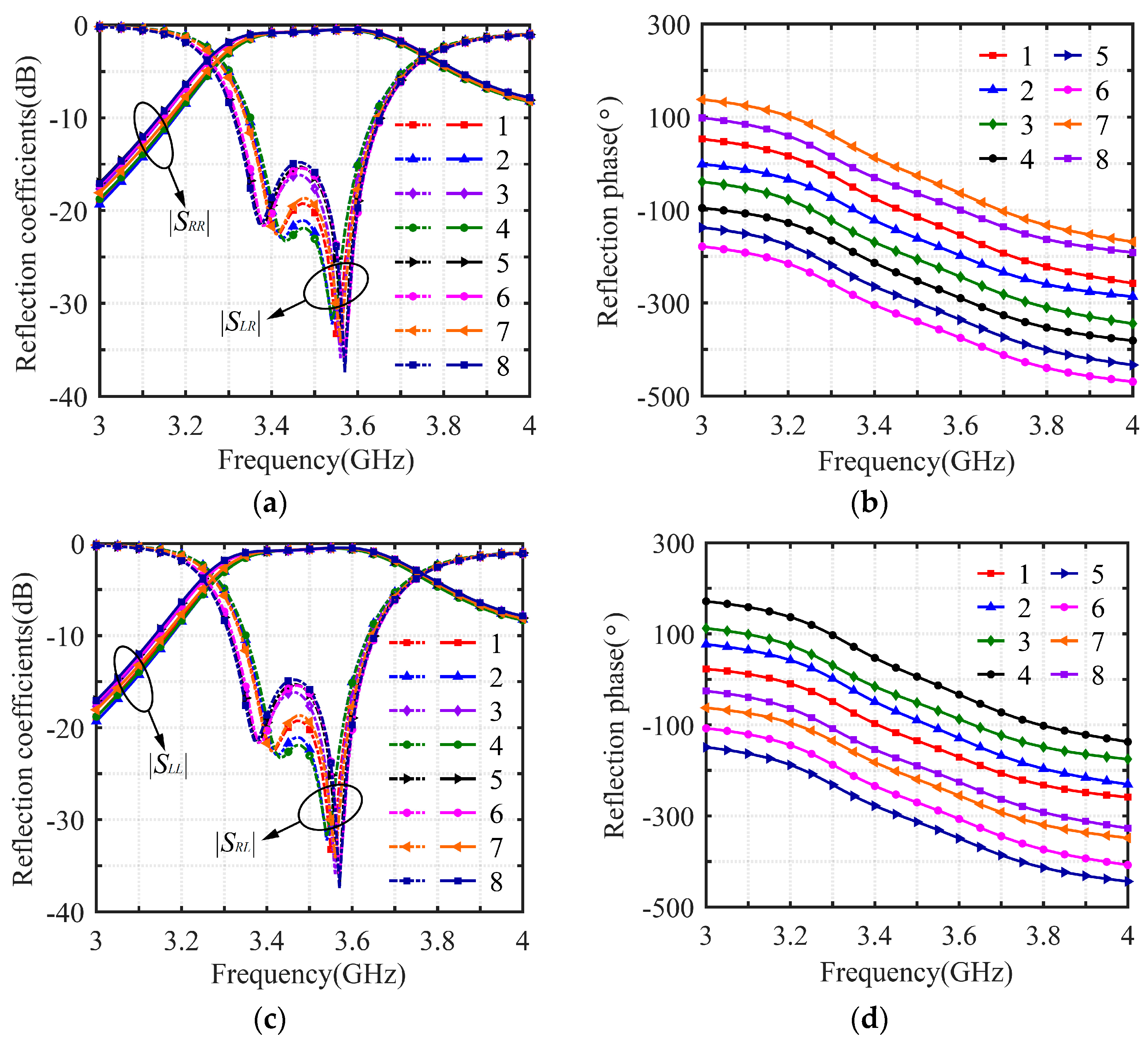
Figure 6.
Influence of the oblique incidence angle on the operating characteristics of the unit: xoz plane (a) reflection amplitude and (b) reflection phase; yoz plane (c) reflection amplitude and (d) reflection phase.
Figure 6.
Influence of the oblique incidence angle on the operating characteristics of the unit: xoz plane (a) reflection amplitude and (b) reflection phase; yoz plane (c) reflection amplitude and (d) reflection phase.
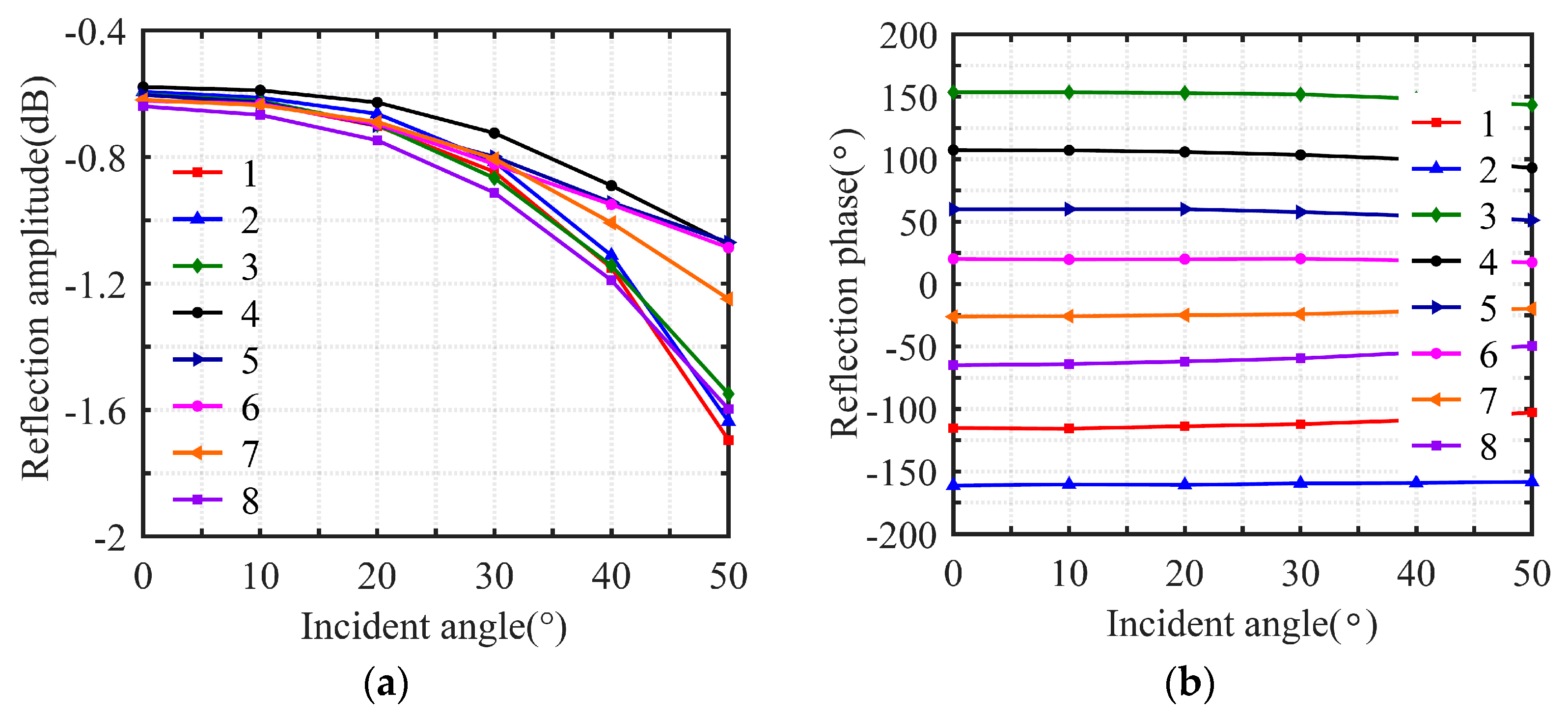

Figure 7.
The efficiency of a reflectarray antenna varies with the position of the feed: (a) height and (b) offset feed angle.
Figure 7.
The efficiency of a reflectarray antenna varies with the position of the feed: (a) height and (b) offset feed angle.

Figure 8.
Structure of the 3-bit circularly polarized reconfigurable reflectarray: (a) model and (b) the distribution diagram of units.
Figure 8.
Structure of the 3-bit circularly polarized reconfigurable reflectarray: (a) model and (b) the distribution diagram of units.

Figure 9.
DC control circuit diagram of PIN diode.

Figure 10.
Right-handed circularly polarized spiral antenna: (a) sample, (b) test scene, (c) reflection coefficient and axial ratio, and (d) radiation pattern.
Figure 10.
Right-handed circularly polarized spiral antenna: (a) sample, (b) test scene, (c) reflection coefficient and axial ratio, and (d) radiation pattern.

Figure 11.
Sample of the 3-bit circularly polarized reconfigurable reflectarray: (a) sample and (b) test scene.
Figure 11.
Sample of the 3-bit circularly polarized reconfigurable reflectarray: (a) sample and (b) test scene.

Figure 12.
Diagram of antenna operating characteristics at 0° beam pointing. Radiation pattern: (a) xoz plane and (b) yoz plane. (c) Gain and axial ratio. (d) Gain of the feed antenna.
Figure 12.
Diagram of antenna operating characteristics at 0° beam pointing. Radiation pattern: (a) xoz plane and (b) yoz plane. (c) Gain and axial ratio. (d) Gain of the feed antenna.

Figure 13.
Measurement results of antenna beam scanning at different frequencies (xoz plane): (a) 3.45 GHz, (b) 3.5 GHz, (c) 3.6 GHz, and (d) 3.7 GHz.
Figure 13.
Measurement results of antenna beam scanning at different frequencies (xoz plane): (a) 3.45 GHz, (b) 3.5 GHz, (c) 3.6 GHz, and (d) 3.7 GHz.

Figure 14.
Measurement results of antenna beam scanning at different frequencies (yoz plane): (a) 3.45 GHz, (b) 3.5 GHz, (c) 3.6 GHz, and (d) 3.7 GHz.
Figure 14.
Measurement results of antenna beam scanning at different frequencies (yoz plane): (a) 3.45 GHz, (b) 3.5 GHz, (c) 3.6 GHz, and (d) 3.7 GHz.

Figure 15.
Comparison of simulation results and measurement results of gain and axial ratio at different scanning angles: (a) xoz plane and (b) yoz plane.
Figure 15.
Comparison of simulation results and measurement results of gain and axial ratio at different scanning angles: (a) xoz plane and (b) yoz plane.

Figure 16.
Radiation pattern of double beam: (a) xoz plane and (b) yoz plane.


Table 1.
Three-bit compensated phase quantization results.
| Calculated compensation phase (°) | [−22.5, 22.5] | [22.5, 67.5] | [67.5, 112.5] | [112.5, 157.5] |
| Quantized compensation phase | 0 | 45 | 90 | 135 |
| Calculated compensation phase (°) | [157.5, 202.5] | [202.5, 247.5] | [247.5, 292.5] | [292.5, 337.5] |
| Quantized compensation phase | 180 | 225 | 270 | 315 |
Table 2.
The comparison of the proposed reconfigurable reflectarray with other works.
| References | [39] | [40] | [25] | [41] | This Work |
|---|---|---|---|---|---|
| Reconfigurable technology | varactor | PIN diode | PIN diode | phased array | PIN diode |
| Number of phase shifts | continuous | 1-bit | 1-bit | / | 3-bit |
| Polarization | linear | Circular | circular | circular | circular |
| Number of diodes | 4 | 4 | 2 | / | 8 |
| Loss of unit | <4 dB | <1 dB | <1 dB | <4.7 dB | <1 dB |
| Angular stability | 40° | / | 30° | / | 50° |
| Aperture efficiency | 25.42% | 15% | 20% | / | 27% |
| Scanning range | ±50°/±50° | ±40°/±40° | −30°~45°/±60° | ±60° | ±60°/±60° |
Disclaimer/Publisher’s Note: The statements, opinions and data contained in all publications are solely those of the individual author(s) and contributor(s) and not of MDPI and/or the editor(s). MDPI and/or the editor(s) disclaim responsibility for any injury to people or property resulting from any ideas, methods, instructions or products referred to in the content. |
© 2024 by the authors. Licensee MDPI, Basel, Switzerland. This article is an open access article distributed under the terms and conditions of the Creative Commons Attribution (CC BY) license (https://creativecommons.org/licenses/by/4.0/).
Share and Cite
MDPI and ACS Style
Chen, Z.; Huang, C.; Yang, X.; Yan, X.; Lin, X.; Zhou, Y. Design of a 3-Bit Circularly Polarized Reconfigurable Reflectarray. Electronics 2024, 13, 1886. https://doi.org/10.3390/electronics13101886
AMA Style
Chen Z, Huang C, Yang X, Yan X, Lin X, Zhou Y. Design of a 3-Bit Circularly Polarized Reconfigurable Reflectarray. Electronics. 2024; 13(10):1886. https://doi.org/10.3390/electronics13101886
Chicago/Turabian StyleChen, Zhe, Chenlu Huang, Xinmi Yang, Xiaoming Yan, Xianqi Lin, and Yedi Zhou. 2024. "Design of a 3-Bit Circularly Polarized Reconfigurable Reflectarray" Electronics 13, no. 10: 1886. https://doi.org/10.3390/electronics13101886
Note that from the first issue of 2016, this journal uses article numbers instead of page numbers. See further details here.