
Numerical Investigation of Rotor and Stator Matching Mode on the Complex Flow Field and Pressure Pulsation of a Vaned Centrifugal Pump


Abstract
:1. Introduction
2. Computational Setup
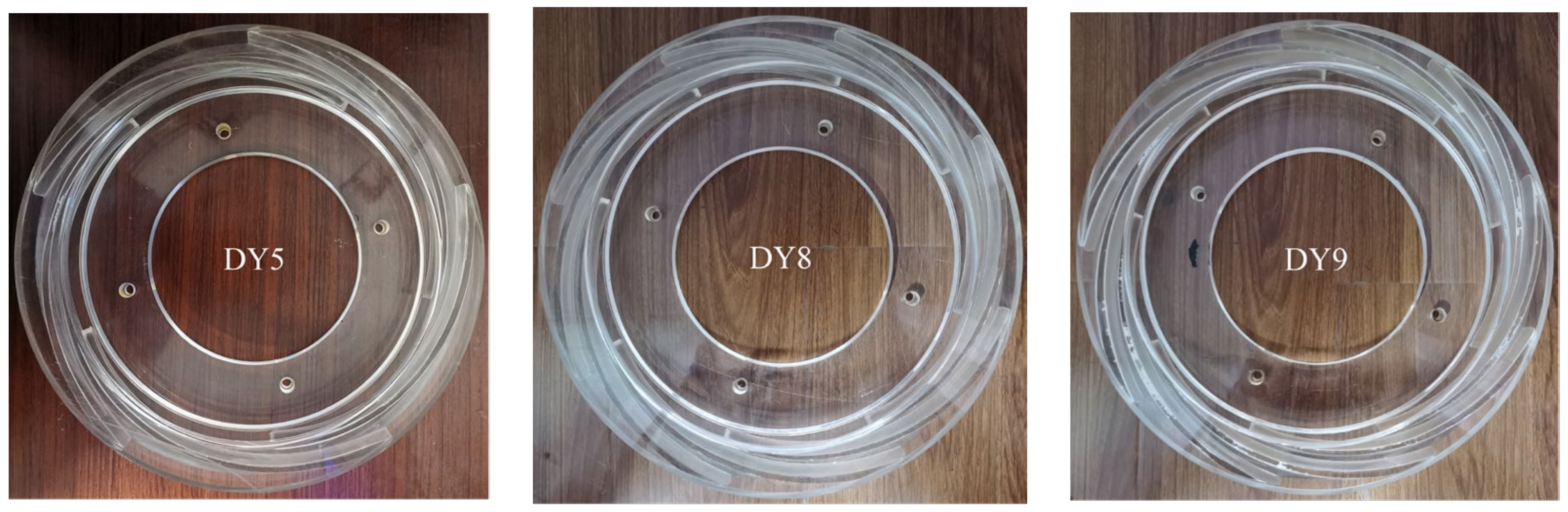
2.1. Model Pump Design
2.2. Calculation Method
2.3. Monitoring Points
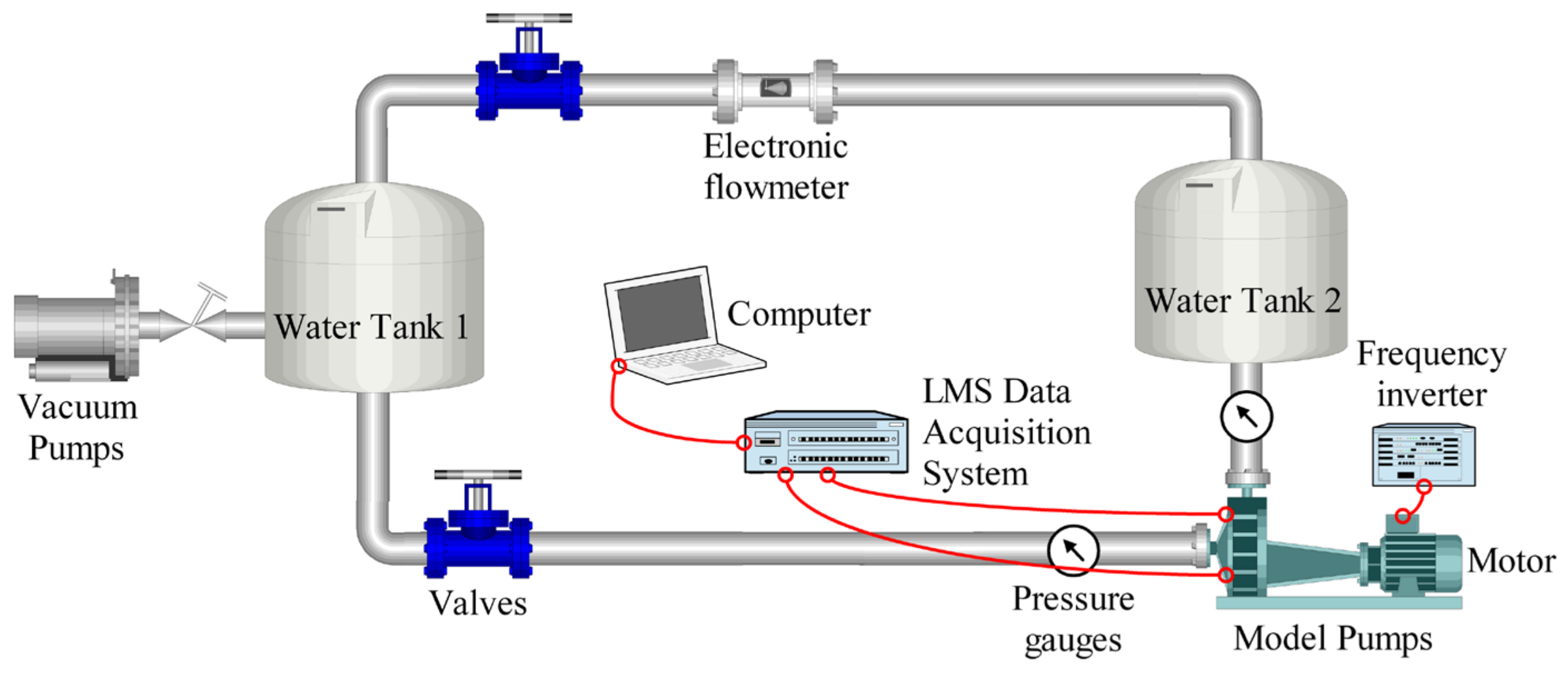
3. Experimental Test Loop
4. Results and Analysis
4.1. Prediction of Pump Performance
4.2. Analysis of Pressure Pulsations
4.3. Unsteady Flow Characteristics
5. Conclusions
- (1)
- The numerical calculation method in this article is well matched with the experimental results, enabling the precise calculation of the complex flow field and pressure pulsation characteristics inside the pump.
- (2)
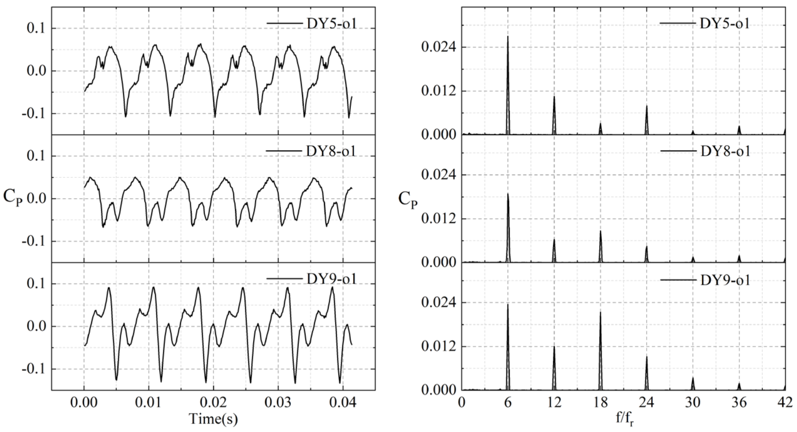
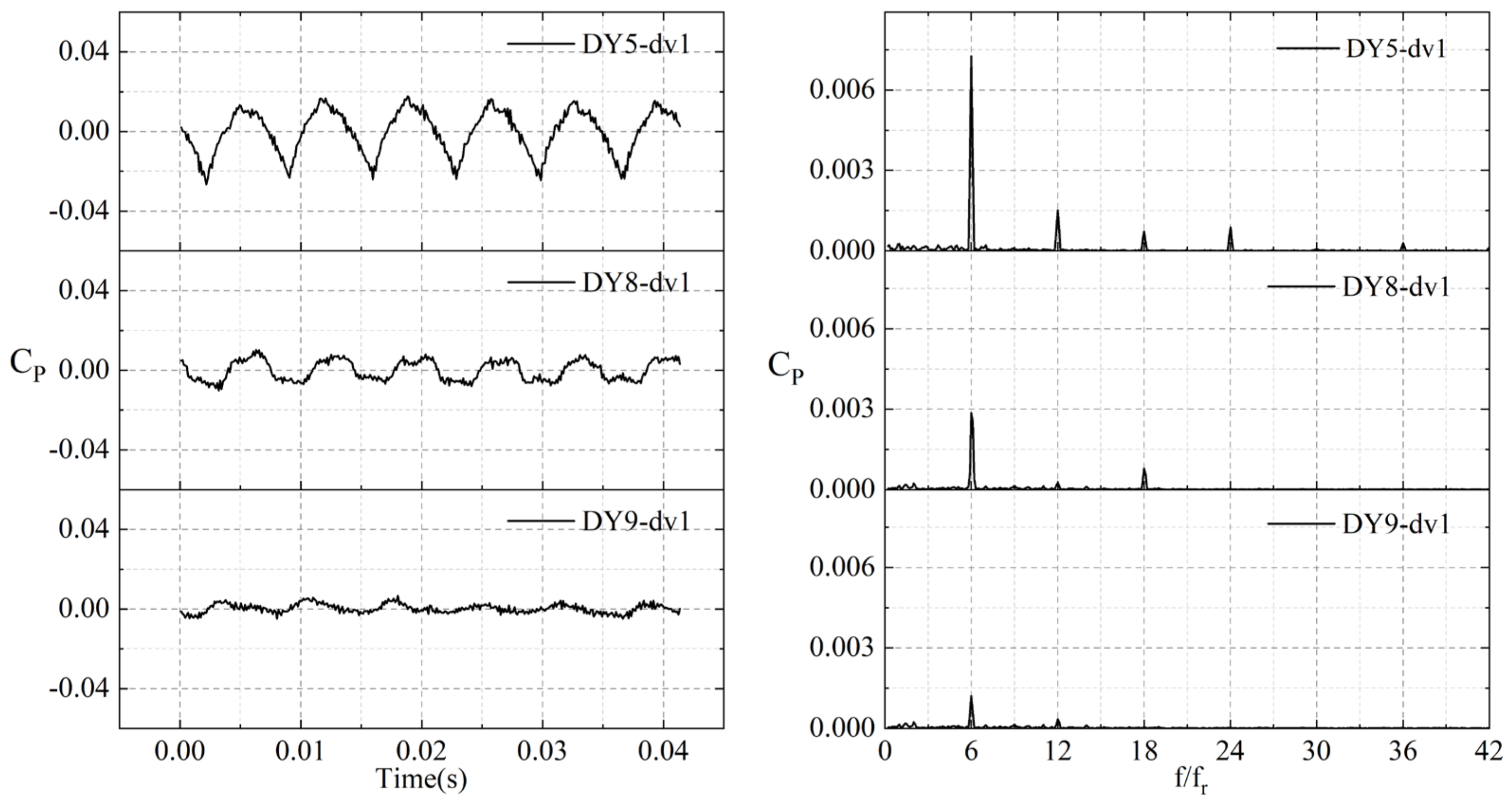
- The matching mode of the rotor and stator significantly affects the time–frequency domain characteristics of the pressure pulsation inside the pump. From the spectrum, it can be seen that the dominant signals in the pressure pulsation spectrum are the blade passing frequency and its harmonics.
- (3)
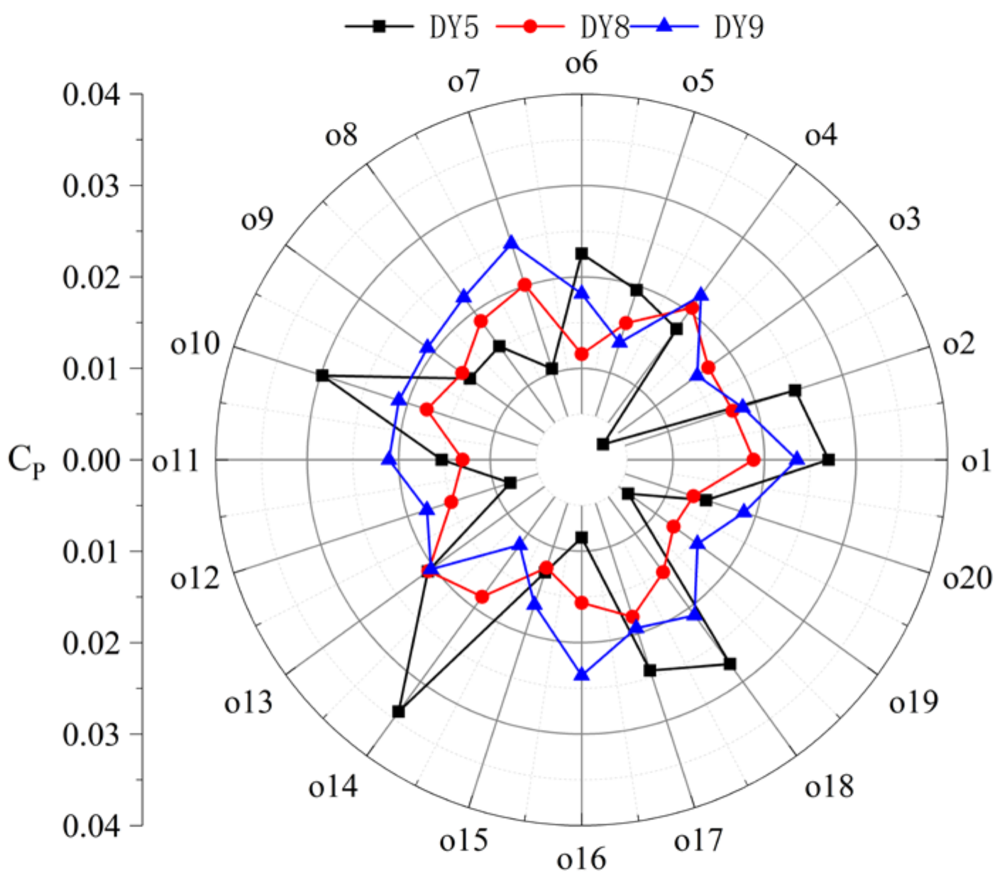
- Through the comparison and analysis of the pressure pulsation energy, it can be seen that the pressure pulsation energy of the DY8 and DY9 model pumps is less than that of the DY5 pump. This implies that appropriately increasing the number of vaned diffuser blades can reduce the pressure pulsation energy induced by the rotor–stator interaction. Therefore, for the design of a low-pressure pulsation pump, a greater number of blades should be adopted.
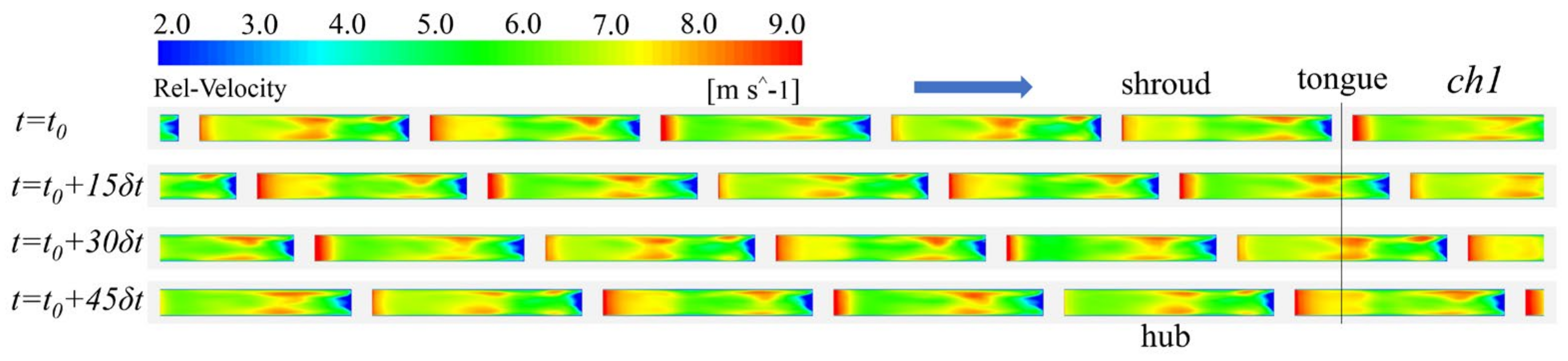
- (4)
- The flow structure of the three pumps is relatively consistent, with a high-speed jet zone appearing on the pressure side and a low-speed wake zone appearing around the suction side. Increasing the number of vaned diffusers improves the distribution of high-energy vortices in the interaction zone, which has a very positive effect on stabilizing the high-speed flow of the fluid inside the centrifugal pump, which is consistent with the conclusions of the pressure pulsation numerical calculations.
Author Contributions
Funding
Institutional Review Board Statement
Informed Consent Statement
Data Availability Statement
Conflicts of Interest
Nomenclature
| Qd | Flow rate, m3/h |
| nd | Rotating speed, r/min |
| Hd | Head, m |
| ns | Specific speed |
| ΦN | Flow coefficient |
| Φ | Flow rate coefficient |
| ΨN | Head coefficient |
| Ψ | Pump head coefficient |
| Zr | Impeller blade number |
| Zs | Diffuser blade number |
| η | Efficiency |
| D1 | Impeller suction diameter, mm |
| D2 | Impeller exit diameter, mm |
| D3 | Diffuser outlet diameter, mm |
| D4 | Volute exit diameter, mm |
| R2 | Impeller outlet radius, mm |
| b2 | Impeller exit width, mm |
| b3 | Diffuser inlet width, mm |
| φ | Volute angle, ° |
| Wrap angle of the blade, ° | |
| u2 | Speed at the impeller exit, m/s |
| β1 | Impeller inlet angle, ° |
| β2 | Blade exit angle, ° |
| β3 | Diffuser inlet angle, ° |
| β4 | Diffuser outlet angle, ° |
| Water density, kg/m3 | |
| A | Pressure value, Pa |
| Cp | Pressure coefficient |
| Q-criterion | Second invariant of the velocity gradient tensor |
| Y+ | Y plus value |
| Time step during calculation, s | |
| fn | Rotating frequency of the shaft, Hz |
| fR | Rotating frequency, Hz |
| fBPF | Blade passing frequency of the rotor, Hz |
| RMS | Root mean square |
References
- Wang, H.Y.; Tan, Z.; Kuang, S.B.; Yu, A.B. Systematic investigation of centrifugal slurry pump under different operating condition by DDPM method. Powder Technol. 2023, 430, 119024. [Google Scholar] [CrossRef]
- Spence, R.; Amaral-Teixeira, J. Investigation into pressure pulsations in a centrifugal pump using numerical methods supported by industrial tests. Comput. Fluids. 2008, 37, 690–704. [Google Scholar] [CrossRef]
- Karpenko, M. Aircraft hydraulic drive energy losses and operation delay associated with the pipeline and fitting connections. Aviation 2024, 28, e0228051. [Google Scholar] [CrossRef]
- Liu, Y.Y.; Yang, G.; Xu, Y.; Peng, F.; Wang, L.Q. Effect of space diffuser on flow characteristics of a centrifugal pump by computational fluid dynamic analysis. PLoS ONE 2020, 15, e0228051. [Google Scholar] [CrossRef] [PubMed]
- Zhang, N.; Li, D.; Gao, B.; Ni, D.; Li, Z. Unsteady Pressure Pulsations in Pumps—A Review. Energies 2023, 16, 150. [Google Scholar] [CrossRef]
- Michal, S.; Mykola, K. Dynamics of Machines and Hydraulic Systems. In Mechanical Vibrations and Pressure Pulsations; Springer: Cham, Switzerland, 2024. [Google Scholar] [CrossRef]
- Wu, J.F.; Li, L.; Yin, Z.C.; Li, Z.; Wang, T.; Tan, Y.F.; Tan, D.P. Mass transfer mechanism of multiphase shear flows and interphase optimization solving method. Energy 2024, 292, 130475. [Google Scholar] [CrossRef]
- Yan, Q.; Fan, X.H.; Li, L.; Zheng, G. Investigations of the mass transfer and flow field disturbance regulation of the gas–liquid–solid flow of hydropower stations. J. Mar. Sci. Eng. 2024, 12, 84. [Google Scholar] [CrossRef]
- Feng, J.; Ge, Z.; Yang, H.; Zhu, G.; Li, C.; Luo, X. Rotating stall characteristics in the vaned diffuser of a centrifugal pump. Ocean Eng. 2021, 229, 108955. [Google Scholar] [CrossRef]
- Jiang, W.; Li, G.; Liu, P.F.; Fu, L. Numerical investigation of influence of the clocking effect on the unsteady pressure fluctuations and radial forces in the centrifugal pump with vaned diffuser. Int. Commun. Heat Mass Transf. 2016, 71, 164–171. [Google Scholar] [CrossRef]
- Gao, B.; Zhang, N.; Li, Z.; Ni, D.; Yang, M.G. Influence of the blade trailing edge profile on the performance and unsteady pressure pulsations in a low specific speed centrifugal pump. ASME J. Fluids Eng. 2016, 138, 051106. [Google Scholar] [CrossRef]
- Barrio, R.; Parrondo, J.; Blanco, E. Numerical analysis of the unsteady flow in the near-tongue region in a volute-type centrifugal pump for different operating points. Comput. Fluids 2010, 39, 859–870. [Google Scholar] [CrossRef]
- Kye, B.; Park, K.; Choi, H.; Lee, M.; Kim, J.H. Flow characteristics in a volute-type centrifugal pump using large eddy simulation. Int. J. Heat Fluid Flow 2018, 72, 52–60. [Google Scholar] [CrossRef]
- Posa, A.; Lippolis, A.; Balaras, E. Large-Eddy Simulation of a Mixed-Flow Pump at Off-Design Condition. J. Fluids Eng. 2015, 137, 101302. [Google Scholar] [CrossRef]
- Posa, A.; Lippolis, A. A LES investigation of off-design performance of a centrifugal pump with variable-geometry diffuser. Int. J. Heat Fluid Flow 2018, 70, 299–314. [Google Scholar] [CrossRef]
- Zhang, N. Excitation Characteristics Induced by Unsteady Flow within a Centrifugal Pump. Ph.D. Dissertation, Jiangsu University, Zhenjiang, China, 2016. [Google Scholar]
- Yuan, Z.; Zhang, Y.; Wang, C. Study on characteristics of vortex structures and irreversible losses in the centrifugal pump. Proc. Inst. Mech. Eng. Part A J. Power Energy 2021, 235, 1080–1093. [Google Scholar] [CrossRef]
- Zhang, N.; Liu, X.; Gao, B.; Xia, B. DDES analysis of the unsteady wake flow and its evolution of a centrifugal pump. Renew. Energy 2019, 141, 570–582. [Google Scholar] [CrossRef]
- Li, D.; Zhang, N.; Jiang, J.; Gao, B.; Alubokin, A.; Zhou, W.; Shi, J. Numerical investigation on the unsteady vortical structure and pressure pulsations of a centrifugal pump with the vaned diffuser. Int. J. Heat Fluid Flow 2022, 98, 109050. [Google Scholar] [CrossRef]
- Keller, J.; Blanco, E.; Barrio, R.; Parrondo, J. PIV measurements of the unsteady flow structures in a volute centrifugal pump at a high flow rate. Exp. Fluids 2014, 55, 1820. [Google Scholar] [CrossRef]
- Wu, Y.L.; Liu, S.H.; Yuan, H.J.; Shao, J. PIV measurement on internal instantaneous flows of a centrifugal pump. Sci. China Technol. Sci 2011, 54, 270–276. [Google Scholar] [CrossRef]
- Feng, J.; Benra, F.K.; Dohmen, H.J. Investigation of Periodically Unsteady. Flow in a Radial Pump by CFD Simulations and LDV Measurements. J. Turbomach. 2011, 133, 186–192. [Google Scholar] [CrossRef]
- Feng, J.J.; Benra, F.K.; Dohmen, H.J. Unsteady flow investigation inrotor-stator interface of a radial diffuser pump. Forsch. Im Ingenieurwesen 2010, 74, 233–242. [Google Scholar] [CrossRef]
- Ni, D.; Zhang, N.; Gao, B.; Li, Z.; Yang, M.G. Dynamic measurements on unsteady pressure pulsations and flow distributions in a nuclear reactor coolant pump. Energy 2020, 198, 117305. [Google Scholar] [CrossRef]
- Liu, X.K. Research on the Unsteady Wake Flow Characteristics of a Centrifugal Pump. Master’s Dissertation, Jiangsu University, Zhenjiang, China, 2019. [Google Scholar]
- Menter, F.; Esch, T. Elements of Industrial Heat Transfer Predictions. Braz. Congr. Mech. Eng. 2001, 109, 650. [Google Scholar]
- Fu, Y.X.; Yuan, J.P.; Yuan, S.Q.; Pace Giovanni d’Agostino Luca Huang, P.; Li, X.J. Numerical and Experimental Analysis of Flow Phenomena in a Centrifugal Pump Operating under Low Flow Rates. J. Fluids Eng. 2015, 137, 011102. [Google Scholar] [CrossRef]
- Ni, D.; Yang, M.G.; Gao, B.; Zhang, N.; Li, Z. Numerical study on the effect of the diffuser blade trailing edge profile on flow instability in a nuclear reactor coolant pump. Nucl. Eng. Des. 2017, 322, 92–103. [Google Scholar] [CrossRef]
- Song, P.F.; Wei, Z.L.; Zhen, H.S.; Liu, M.L.; Ren, J. Effects of pre-whirl and blade profile on the hydraulic and cavitation performance of a centrifugal pump. Int. J. Multiph. Flow 2022, 157, 104261. [Google Scholar] [CrossRef]
- Zhang, N.; Yang, M.G.; Gao, B.; Li, Z.; Ni, D. Experimental and numerical analysis of unsteady pressure pulsation in a centrifugal pump with slope volute. J. Mech. Sci. Technol. 2015, 29, 4231–4238. [Google Scholar] [CrossRef]
- González, J.; Fernández, E.; Blanco, C. Santolaria Numerical simulation of the dynamic effects due to impeller-volute interaction in a centrifugal pump. ASME J. Fluids Eng. 2002, 124, 48–335. [Google Scholar] [CrossRef]
- Hunt, J.; Wray, A.; Moin, P. Eddies, streams, and convergence zones in turbulent flows. Stud. Turbul. Using Numer. Simul. Databases 1988, 1, 193–208. [Google Scholar]


| Parameters | Value |
|---|---|
| Flow rate, QN | 55 m3/h |
| Head, Hd | 20 m |
| Rotation speed, nd | 1450 r/min |
| Specific speed, ns | 69 |
| Blade number, Zr | 6 |
| Diffuser blade number, Zs | 5, 8, 9 |
| Impeller suction diameter, D1 | 80 mm |
| Impeller exit diameter, D2 | 250 mm |
| Volute exit diameter, D4 | 100 mm |
| Impeller outlet width, b2 | 15 mm |
| Impeller inlet angle, β2 (shroud to hub) | 25.6~37.3° |
| Impeller blade wrap angle, φ | 125° |
| Impeller blade exit angle, β2 | 25° |
| Diffuser inlet width, b3 | 21 mm |
| Diffuser outlet diameter, D3 | 320 mm |
| Diffuser outlet angle, β4 | 17° |
| Diffuser inlet angle, β3 | 7° |
| Volute angle, φ | 30° |
| Speed at the impeller exit, u2 | 18.98 m/s |
| Model Pump | Flow Coefficient | Head Coefficient | Hydraulic Efficiency |
|---|---|---|---|
| DY5 | 1.0 QN | 0.5660 | 82.13% |
| DY8 | 1.0 QN | 0.5750 | 82.52% |
| DY9 | 1.0 QN | 0.5768 | 82.91% |
| Scheme | fBPF | 2fBPF | 3fBPF |
|---|---|---|---|
| Exp | 0.0153 | 0.0048 | 0.0059 |
| DDES | 0.0187 | 0.0063 | 0.0086 |
| Error | 18.18% | 23.81% | 31.40% |
Disclaimer/Publisher’s Note: The statements, opinions and data contained in all publications are solely those of the individual author(s) and contributor(s) and not of MDPI and/or the editor(s). MDPI and/or the editor(s) disclaim responsibility for any injury to people or property resulting from any ideas, methods, instructions or products referred to in the content. |
© 2024 by the authors. Licensee MDPI, Basel, Switzerland. This article is an open access article distributed under the terms and conditions of the Creative Commons Attribution (CC BY) license (https://creativecommons.org/licenses/by/4.0/).
Share and Cite
Du, L.; Zheng, F.; Gao, B.; Gad, M.; Li, D.; Zhang, N. Numerical Investigation of Rotor and Stator Matching Mode on the Complex Flow Field and Pressure Pulsation of a Vaned Centrifugal Pump. Energies 2024, 17, 2416. https://doi.org/10.3390/en17102416
Du L, Zheng F, Gao B, Gad M, Li D, Zhang N. Numerical Investigation of Rotor and Stator Matching Mode on the Complex Flow Field and Pressure Pulsation of a Vaned Centrifugal Pump. Energies. 2024; 17(10):2416. https://doi.org/10.3390/en17102416
Chicago/Turabian StyleDu, Leilei, Fankun Zheng, Bo Gao, Mona Gad, Delin Li, and Ning Zhang. 2024. "Numerical Investigation of Rotor and Stator Matching Mode on the Complex Flow Field and Pressure Pulsation of a Vaned Centrifugal Pump" Energies 17, no. 10: 2416. https://doi.org/10.3390/en17102416