Modelling Wear Phenomena Specific to Mixer Blades in Concrete Production Plants
by
 , , ,
, , ,
Marius Gabriel Petrescu
1 ,
,
Aristia-Ioana Popovici
2,*,
Adrian Niță
1,*,
Dan Isbășoiu
1,
Teodor Dumitru
1 and
Maria Tănase
1 1
Mechanical Engineering Department, Petroleum–Gas University of Ploiești, 100680 Ploiești, Romania
2
Department of Machines and Advanced Technologies in Construction, Technical University of Civil Engineering of Bucharest, 021407 Bucharest, Romania
*
Authors to whom correspondence should be addressed.
Appl. Sci. 2024, 14(10), 3988; https://doi.org/10.3390/app14103988
Submission received: 27 March 2024
/
Revised: 30 April 2024
/
Accepted: 7 May 2024
/
Published: 8 May 2024
(This article belongs to the Section Surface Sciences and Technology)
Abstract
:In the cement concrete manufacturing industry, mixers are critical pieces of equipment that play an essential role. Mixers ensure, by mechanically mixing the materials that make up the concrete, the homogeneity of the mixture. Since the active elements of the mixer in the concrete industry—the mixing blades—come into permanent contact with the mineral aggregates in the mixture formed by water and cement, they are permanently subjected to a strong abrasive–erosive wear process. The authors of this article were concerned with the establishment of tribological models for studying the wear of mixing blades, in order to identify the influence of their constructive parameters on the wear intensity. A complex model (Kraghelsky–Nepomnyashchi model) was adopted for the study. The modeling results revealed that the wear intensity decreases with an increasing blade angle of attack and increases linearly with increasing speed, as well as with an increasing friction coefficient. The modeling results confirm that the wear intensity is lowest when the mixing blade is inclined at a 60° angle, while the highest value is recorded for 30°. By identifying the angle at which the greatest wear of blades occurs, interventions can be made in the design of a more durable mixer (with the optimal installation angle of the mixer blades), thus requiring fewer corrective maintenance interventions. Based on these findings, we conclude that the complex model used in the experiment can provide a convenient and efficient tool for the study of erosive–abrasive phenomena.
1. Introduction
Industrial mixers are pieces of equipment used to mechanically mix different categories of materials to obtain homogeneous mixtures.
The quality of cement concrete depends, to a large extent, on the homogeneity of the mixture formed by cement and mineral aggregates, in combination with water. The homogeneity of this mixture is ensured mainly by the geometrical (inclination angle) and functional (mixing speed or blade speed) characteristics of the mixing blades of the mixer.
The importance of the homogeneity of the concrete mix is also mentioned in paper [1], where the compositional factors affecting the quality of the concrete mix are described and the efficiency of concrete mix production is analyzed; this is largely determined by the availability of quality management tools at all stages of the technological process.
In the scientific work [2], the authors studied the influence of the mixing time and methods used for mixing cement on the homogeneity and mechanical characteristics of concrete cement. For the effective homogenization of the concrete components, the geometric characteristics of the mixer are essential. Also, in [3], an analysis of the geometrical elements of a vertical mixer (with a frustoconical body) is performed in order to establish the optimal dimensional values of the mixer bowl and the mixing blades. At the same time, the authors establish, for the mixing blades inclination angle, a recommended value of 30–45°, ensuring the optimal homogeneity of the concrete mixture.
However, geometrical and functional elements are also important for characterizing the durability of a concrete mixer, taking into account that mixers in the concrete industry operate under conditions characterized by abrasive–erosive wear [4,5,6,7]. In this context, it is interesting to establish the extent to which the functional characteristics of a mixer influence the lifetime of its components, determined, in particular, by the wear rate size (usually evaluated by the mass loss) of the mixing blades.
In the article [8], we studied the influence of the inclination angle of the mixing blade active face, relative to the shaft axis, on the ratio between the friction force (manifested on the surface of the mixing blade) and the weight of the aggregate material in the mixer tank. In their research, the authors used an experimental stand that reproduced, by dimensional similarity, a real horizontal mixer. Starting from the hypothesis that the wear of the mixing blades depends, in a major way, on the friction of the aggregate particles on their surface, a specific analytical model was created (Figure 1) based on the relative displacement between the aggregate particles and mixing blades.
As presented in the work [9], mixing blades are subject to a complex and difficult-to-control wear phenomenon. The blades wear is determined by the impact and abrasion of a mixture of particles of variable size and shape—some of very small size (sand, cement, and adhesives) and others of larger size (mineral aggregates)—in combination with the corrosive effect of the solution cement. The level of mechanical stress and the degree of degradation manifested at the level of the mixing blades, as mentioned in the results of various scientific research works [10,11,12,13], depend on their material hardness, the impact speed of the aggregate particles, and the value of the impact angle.
Studying wear in the mixing blades of mixers, Julian Fasano et al. [10] highlighted the fact that the erosion rate depends on the following environmental factors: the chemical composition of the mixture, the hardness of solid particles, the density of solid particles, the percentage of solid particles, the shape of solid particles, and the size of the solid particles. The dynamic factors that affect the erosion rate, which are shown in study [10], are the flow regime of the fluid, the impact speed on the blade surface, the impact frequency, and the impact angle.
The above statements were also confirmed by the results already mentioned in [9,10,11,12,13,14]. Through experiments carried out on a stand that reproduces (1:2 scale) a drum from the composition of a horizontal mixer with a double axis, in the work [15], it was possible to establish the dependence between the type of material and the wear rate of the mixing blades, as well as the influence exerted by the angle of attack. The stand had the possibility to change the value of the attack angle of the mixing blades, corresponding to the following values: 30°, 45°, and 60°. In the experimental research, samples/specimens made from three types of cast iron alloyed with chromium [15] were used, specific to the construction of mixing blades, as well as three types of steel. The working environment was a mixture of crushed mineral aggregates corresponding to the granulometric class 4–8 mm.
The results obtained from the experiments [8,9,10,11,12,13,14] showed that with an increase in the inclination angle of blades, wear through erosion becomes predominant, accelerating the phenomenon of mechanical degradation in the samples; the small angle of inclination of the blades largely restrains the movement of aggregates on the sample surface, reducing the erosive effect. In this situation, impact wear becomes predominant, the speed being directly proportional to the resistance characteristics of the sample material.
Zhang et al. [16] studied the wear of the mixing blades of a mixer, in accordance with the pressure exerted by the concrete mixture on the blade surface. The results revealed lower wear values for tilt angles between 30° and 40°.
Therefore, it can be stated that theoretical and experimental research into erosive wear processes has been a key interest for many experts in the field of tribology [17,18,19,20,21,22,23,24]. The development of abrasive erosion models is defined by a technical level of theoretical and experimental investigation resources that are currently being rapidly improved.
The results of the erosion research were obtained via the development of mathematical models specific to these tribological processes. In his study, Meng [25] presented and analyzed 28 such models. The empirical models are developed from the experimental data from material erosion in the laboratory test rig. In essence, mathematical models of erosion suggest calculation equations for the intensity of erosive wear, depending on the geometric and dynamic parameters of the studied system and also on the chemical characteristics of the operating environment.
Interest in the tribological modeling of erosion phenomena is also shown in [26], where an analysis of variance (ANOVA) was performed to statistically analyze the effect and contributions of specific metal-cutting parameters on the response variables, namely: tool life, surface roughness, volume of material removed, power consumption, and cutting zone temperature. The effect of the surface quality on the functionality of the systems benefits, apart from the approach based on the classic tribological theories, from the development of unconventional models, as it results from [27].
Taking into account these considerations, we can state that the subject addressed in this article complements other studies in the field and confirms the previous results obtained by the authors of this paper and the results published by other authors.
2. Materials and Methods
In this scientific article, the authors present the hypotheses and results of the application of specific models for studying the behavior of the mixing blades of a horizontal mixer to the erosive–abrasive action of solid particles in a concrete mixture. Starting from the model of an experimental stand [8] used to study the effect of the inclination angle of the mixing blades on their wear, the authors of this paper present the results of the mathematical modeling regarding the impact of the aggregate particles from the concrete mix on mixing blade wear. As stated in [10], the erosion rate essentially depends, among many factors, on the dynamic factors: the impact speed on the blade surface, the impact frequency, and the impact angle. Paper [8] also proposes dynamic modeling for the flow of aggregate particles on the surface of the mixing blade, establishing the relationship between the blade inclination angle and the friction intensity on its surface. The experimental results were in good agreement with the dynamic model.
This article continues the presentation of the results [8], focusing on the tribological modeling of the interaction between aggregate particles and the surface of the mixer blade.
The research followed the work scheme shown in Figure 2.
The initial data regarding the mixing blade and mineral aggregates are consistent with those in [8,9,14,15,28]:
- -
- The material from which the mixing blades are made is cast iron alloyed with chrome;
- -
- The angle of incidence of the abrasive particles (mineral aggregate) is given by the value of the angle of attack of the mixing blades, with the values: 30°, 45°, and 60°;
- -
- -
- The specific speed of the aggregate particle has the value of 2.5 m/s, in correspondence with the real mixer (the double-shaft mixer studied, located in the concrete station of the company Strabenbau Logistic SRL, Blejoi, Prahova, Romania, was a twin-shaft type, with a capacity of 2 m3, produced by CM Srl., Conselice, Italy/SICOMA, Ponte Valleceppi, Italy) [26], for which the speed of the experimental stand [8] was adopted, with the study being carried out under accelerated conditions.
To study the effect of mineral aggregate particles (abrasive particles) on the mixing blades of the concrete mixer, the complex Kraghelsky–Nepomnyashchi model was used. Many studies have been developed regarding the solid particle erosion mechanism and a variety of erosion models were proposed. The erosion is influenced by different parameters, and most of the models [29] consider the particle characteristics (size, number, shape, etc.), fluid properties (it can affect the impact velocity of the particles), particle impact speed, and particle impact angle.
In general, theoretical models of erosion take into account the impact conditions of the erosion mechanism. The material is removed from the target surface due to cutting, the deformation mechanism, or both processes. The complex model described in the following study takes into account only the type of deformation of the target surface.
It was considered—based on studying the literature—that this model best captures the interaction of abrasive particles with the surfaces of moving parts [25,30]. The model considers the abrasive particles to have a spherical shape and to be perfectly rigid. Such a particle strikes the surface at a certain velocity, at an angle of incidence in the range (oblique and normal impact, respectively). The interaction of the abrasive particle with the eroded surface is illustrated graphically in Figure 3, and then, by applying the model, the volume of deformed material is calculated.
The mechanical impact of the abrasive particle with the worn surface causes elastic or plastic deformation of the material, induces specific friction processes caused by the sliding of the particle on the surface, and develops characteristic fatigue processes on repeated contact.
This is synthetically expressed by the Nepomnyashchi model describing the process of wear particle formation by erosion and underlying the calculation of the wear intensity of this process [30,31]. According to Nepomnyashchi’s model, the apparition of the wear particle is primarily caused by the fatigue that follows the solid particle’s friction in the impact process and surface deformation.
The erosion wear intensity is defined as the ratio between the cumulative mass loss of the removed material through wear of the target surface (muz) and the mass of the erosive particles that produced this wear (mab) and is calculated using the equation:
Considering the Nepomnyashchi model and the Kraghelski relations, the number of cycles at which particle detachment occurs is determined, depending on the deformation state of the worn surface material.
For elastic and plastic deformations, the calculation relations are
Under the effect of the kinetic energy, the solid particle deforms the surface and it slides relatively to it, generating a friction force. The elementary path of friction is determined on the basis of the contact surface’s dimensions; thus, the elementary volume of the worn material (the volume of material worn in the elastic deformation regime, Ve or the plastic one, Vp) over the surface is determined via the equation:
The differences in the considered deformation depend on the number of cycles at which the material is detached.
The integral in the relation is calculated via the law of variation in surface deformation and the limit of integration (for which the coefficients are highlighted in Table 1).
The calculation of the erosive wear intensity Ier is performed using the equations from Figure 4, considering three distinct cases (H1, H2, and H3) related to the kinematics of the particle with the surface:
- The tangential component of the particle velocity cancels with increasing surface deformation ()—case H1;
- The tangential component of the particle velocity cancels as the surface deformation does ()—case H2;
- The tangential component of the particle velocity does not cancel in the process of surface deformation ()—case H3.
Under certain conditions, erosion manifests itself as pure abrasion; the transition can be judged by the relationship between the angle of incidence (α0) of the particle on the target surfaces and the critical angle of incidence () at which microbursting occurs:
—is determined from the wear particle production condition at a single stress cycle ().
Angle is determined using the following equations:
- -
- for elastic deformation:
- -
- for plastic deformation:
Based on the working hypotheses mentioned above, the analysis of erosive–abrasive phenomena for concrete mixer blades (Figure 1) was carried out by applying the complex Kraghelsky–Nepomnyashchi model. This model assumes that the spherical abrasive particle deforms the surface it strikes either elastically or plastically, dependent on the motion characteristic (sliding or rolling) of the particle upon contact. Thus, the erosive wear intensity can be calculated by taking into account the type of deformation in the surface, with the equations shown in Figure 4.
Table 2 lists the mixer blade specific parameters involved in the erosive wear intensity calculation relationships, with the complex model and their values.
With the specified relationships and parameters, the variation in erosive intensity in the following cases was analyzed:
- —Variation as a function of the angle of incidence, for the velocity v0 = 2.5 m/s, for three considered values of the friction coefficient (µ: 0.25, 0.3, and 0.35);
- —Variation as a function of impact velocity, for µ = 0.25, for three values of the angle of incidence (α0: 30°, 45°, and 60°);
- —Variation as a function of the friction coefficient, for the velocity v0 = 2.5 m/s, for three values of the angle of incidence (α0: 30°, 45°, and 60°).
3. Results and Discussion
Figure 5, Figure 6 and Figure 7 show the results obtained both for elastic deformation and plastic deformation of the surface under wear.
The interpretation of the modelling results, presented as graphs in Figure 5, Figure 6 and Figure 7, is as follows:
- (a)
- Depending on the angle of impact, three values of the coefficient of friction (Figure 5):
- ⮚
- Elastic deformation:
- The maximum value of the erosion intensity occurs at an angle of approx. 30–35°, and its value decreases as the friction coefficient increases;
- Between the angle values of 50 and 65°, the wear intensity becomes zero, and the values depend on the friction coefficient (the higher the friction coefficient, the lower the angle value at which the intensity is zero);
- Between angle 50° and 90° a maximum wear intensity value of 70–75° is repeated, but much lower than the wear intensity at 30°;
- ⮚
- Plastic deformation:
- The maximum value of erosion intensity occurs at an angle of approximately 15°;
- Between the angle values of 55 and 65°, the wear intensity becomes zero;
- Between the angle values of 55° and 90°, a maximum wear intensity value of 70° is repeated, but much lower than the wear intensity at 30°;
- (b)
- Depending on the impact speed, three impact angle values (Figure 6):
- ⮚
- Elastic deformation:
- The intensity of wear is almost constant at 60°;
- For lower impact-angle values (30° and 45°), the wear intensity increases exponentially with the change in speed, the slope being differentiated and influenced by the size of the angle, and the maximum value being at 45°;
- ⮚
- Plastic deformation:
- The wear intensity increases linearly with increasing speed; the slope is differentiated by the angle size, and the larger the angle value, the smaller the influence of speed on the wear intensity;
- (c)
- Depending on the friction coefficient, three values of the impact angle (Figure 7):
- ⮚
- Elastic deformation:
- For a 30° angle: the wear intensity has a parabolic variation according to the value of the friction coefficient, for two areas, 0–0.7 and 0.7–0.9, with the maximum value for wear intensity in the middle of the intervals and the minimum value for a friction coefficient of 0.7 and 0.85; above 0.85, the variation becomes exponential;
- For a 45° angle: the wear intensity has a parabolic variation according to the value of the friction coefficient, for two ranges, 0–0.4 and 0.4–0.5, with the maximum value for wear intensity at the halfway point of the ranges and the minimum value for a friction coefficient of 0.4 and 0.5; above 0.5, the variation becomes exponential.
- For a 60° angle: the wear intensity has a parabolic variation depending on the value of the friction coefficient, for two ranges, 0–0.25 and 0.25–0.35, with the maximum value at the halfway point of the range and the minimum value of the wear intensity for a friction coefficient of 0.2 and 0.3; above 0.3, the variation becomes exponential up to the value friction coefficient 0.55; above this, the variation begins linearly decreasing depending on the value of the friction coefficient.
- ⮚
- Plastic deformation:
- The wear intensity increases linearly with the increasing friction coefficient up to the value of 0.3; above this value, the increase becomes exponential for 30° and 45° and decreases for 60°; the slope is differentiated by the angle size, and the smaller the angle value, the greater the influence of the friction coefficient;
- The maximum values of wear intensity are recorded for the 0.35 friction coefficient value; the smaller the angle, the higher the value for the erosion intensity.
4. Conclusions
Based on the literature references and the theoretical and experimental investigations carried out by the authors, it can be concluded that the complex Kraghelsky–Nepomnyashchi model is suitable for the study of elasto-plastic deformations in the material of mixing blades subjected to the erosive–abrasive action of mineral aggregate particles acting under varying angles of incidence.
The results obtained from the application of the model are consistent with the results of the analytical model presented in [8] and the experimental research from the works [8,9,10,11,12,13,14]. This justifies considering that the complex model can provide a convenient and effective tool for the study of erosive–abrasive phenomena.
Regarding the influence of the geometrical parameters of the mixer blade—its angle of attack—on the wear intensity, the following conclusions can be drawn:
- The wear intensity decreases with the increase in the angle of attack of the mixing blade; the lowest values of wear intensity are noted at the 60°angle of attack;
- The wear intensity increases linearly with increasing speed; the slope is differentiated by the size of the angle, and the larger the angle value, the smaller the influence of speed on the wear intensity;
- The wear intensity increases with an increasing coefficient of friction; the slope is differentiated by the size of the angle, and the smaller the angle value, the greater the influence of the friction coefficient.
The results of the study are in agreement with the mentions of [10], highlighting the fact that the dynamic factors that affect the erosion speed are the impact speed on the blade surface, the impact frequency, and the impact angle.
Regarding the geometric factor—the angle of inclination of the mixing blade—the modeling results are consistent with those mentioned in paper [8]; namely, the minimum intensity of wear is noted at angles of inclination of 60°. The same conclusion was also obtained in paper [16], with the minimum values of the maximum pressure on the mixing blade corresponding to higher values of the inclination angle of 50°.
In order to satisfy the conditions forthe efficiency of the concrete mixture homogenization [3] and those for wear reduction, a compromise must be established regarding the angle of inclination of the mixing blades. If the maximum homogenization corresponds to an angle of about 30°, then the minimum wear is noted at high values of the angle −60°.
As there are currently no specific methodsto predict the rate of erosion, studies dedicated to each application should be carried out—for reasonable costs, research should be carried out on a small scale—with the reconstruction, as much as possible, of the real environment. For a reasonable study duration, the dynamic parameters should be increased, so that tests are performed at an accelerated rate. The conclusions, of a qualitative order, could later be correlated with the real scale to establish the correct wear parameters.
Further studies on the wear of mixing blades and the development of methods to model the wear phenomena, taking into account the dynamic aspects and the characteristics of the materials, could facilitate the supervision of failures in concrete manufacturing plants and help in the effective programming of maintenance works. Further research can be carried out, considering the number of particles that erode the surface. Most mathematical models are theoretical, and the premises must be correlated with experimental research and can be improved with correlation coefficients, which are commonly differentiated considering the deformation state. The erosion model can be used in future research in combination with the flow pattern.
Author Contributions
Conceptualization, M.G.P.; Methodology, M.G.P. and A.N.; Software, A.-I.P.; Formal analysis, A.-I.P., D.I. and T.D.; Investigation, M.G.P.; Resources, T.D.; Writing—original draft, A.-I.P. and A.N.; Writing—review & editing, D.I. and M.T. All authors have read and agreed to the published version of the manuscript.
Funding
This research received no external funding.
Data Availability Statement
Data are contained within the article.
Conflicts of Interest
The authors declare no conflicts of interest.
References
- Anatoly Fedorovich, T.; Drozdov, A. Automatic Control of the Concrete Mixture Homogeneity in Cycling Mixers. IOP Conf. Ser. Mater. Sci. Eng. 2018, 317, 012043. [Google Scholar] [CrossRef]
- Zhao, W.; Yang, J.; Zhao, W.; Yang, C. Experimental Study on the Influence of Mixing Time on Concrete Performance under Different Mixing Modes. Sci. Eng. Compos. Mater. 2021, 28, 638–651. [Google Scholar] [CrossRef]
- Stel’makh, S.A.; Shcherban’, E.M.; Shuiskii, A.I.; Prokopov, A.Y.; Madatyan, S.M.; Parinov, I.A.; Cherpakov, A.V. Effects of the Geometric Parameters of Mixer on the Mixing Process of Foam Concrete Mixture and Its Energy Efficiency. Appl. Sci. 2020, 10, 8055. [Google Scholar] [CrossRef]
- Cazacliu, B. In-Mixer Measurements for Describing Mixture Evolution during Concrete Mixing. Chem. Eng. Res. Des. 2008, 86, 1423–1433. [Google Scholar] [CrossRef]
- Ferraris, C.F. Concrete Mixing Methods and Concrete Mixers: State of the Art. J. Res. Natl. Inst. Stand. Technol. 2001, 106, 391. [Google Scholar] [CrossRef] [PubMed]
- Valigi, M.C.; Logozzo, S.; Landi, L.; Braccesi, C.; Galletti, L. Twin-Shaft Mixers’ Mechanical Behavior Numerical Simulations of the Mix and Phases. Machines 2019, 7, 39. [Google Scholar] [CrossRef]
- Labiapari, W.S.; Gonçalves, R.J.; De Alcântara, C.M.; Pagani, V.; Di Cunto, J.C.; De Mello, J.D.B. Understanding Abrasion-Corrosion to Improve Concrete Mixer Drum Performance: A Laboratory and Field Approach. Wear 2021, 477, 203830. [Google Scholar] [CrossRef]
- Niță, A.; Laudacescu, E.; Petrescu, M.G.; Dumitru, T.; Burlacu, A.; Bădoiu, D.G.; Tănase, M. Experimental Research Regarding the Effect of Mineral Aggregates on the Wear of Mixing Blades of Concrete Mixers. Materials 2023, 16, 5047. [Google Scholar] [CrossRef] [PubMed]
- Niță, A.; Petrescu, M.G.; Dumitru, T.; Burlacu, A.; Tănase, M.; Laudacescu, E.; Ramadan, I. Experimental Research on the Wear Behavior of Materials Used in the Manufacture of Components for Cement Concrete Mixers. Materials 2023, 16, 2326. [Google Scholar] [CrossRef]
- Fasano, J.; Janz, E.E.; Myers, K. Design Mixers to Minimize Effects of Erosion and Corrosion Erosion. Int. J. Chem. Eng. 2012, 2012, 171838. [Google Scholar] [CrossRef]
- Sapate, S.G.; RamaRao#, A.V. Effect of Erodent Particle Hardness on Velocity Exponent in Erosion of Steels and Cast Irons. Mater. Manuf. Process. 2003, 18, 783–802. [Google Scholar] [CrossRef]
- Stack, M.M.; Stott, F.H.; Wood, G.C. The Significance of Velocity Exponents in Identifying Erosion-Corrosion Mechanisms. J. Phys. IV Fr. 1993, 3, C9-687–C9-694. [Google Scholar] [CrossRef]
- Khalid, Y.A.; Sapuan, S.M. Wear Analysis of Centrifugal Slurry Pump Impellers. Ind. Lubr. Tribol. 2007, 59, 18–28. [Google Scholar] [CrossRef]
- Niță, A. Contributions to Increase the Wear Resistance of Mixers in Concrete Production Plants; Scientific Research Report No. 3; Petroleum Gas University of Ploiesti: Ploiesti, Romania, 2023. [Google Scholar]
- Niță, A. Contributions to the Study of Specific Wear Phenomena of Mixers in Concrete Production Plants; Scientific Research Report No. 2; Petroleum Gas University of Ploiesti: Ploiesti, Romania, 2023. [Google Scholar]
- Zhang, H.; Feng, P.; Ying, W. Abrasive Wear and Optimal Installation Angle of Concrete Double-Horizontal Shaft Mixer Stirring Blades. SN Appl. Sci. 2020, 2, 1067. [Google Scholar] [CrossRef]
- Arabnejad, H.; Mansouri, A.; Shirazi, S.A.; McLaury, B.S. Development of Mechanistic Erosion Equation for Solid Particles. Wear 2015, 332–333, 1044–1050. [Google Scholar] [CrossRef]
- Mansouri, A.; Arabnejad, H.; Shirazi, S.A.; McLaury, B.S. A Combined CFD/Experimental Methodology for Erosion Prediction. Wear 2015, 332–333, 1090–1097. [Google Scholar] [CrossRef]
- Ashrafizadeh, H.; Ashrafizadeh, F. A Numerical 3D Simulation for Prediction of Wear Caused by Solid Particle Impact. Wear 2012, 276–277, 75–84. [Google Scholar] [CrossRef]
- Hadavi, V.; Moreno, C.E.; Papini, M. Numerical and Experimental Analysis of Particle Fracture during Solid Particle Erosion, Part II: Effect of Incident Angle, Velocity and Abrasive Size. Wear 2016, 356–357, 146–157. [Google Scholar] [CrossRef]
- Zhu, H.; Lin, Y.; Zeng, D.; Zhou, Y.; Xie, J.; Wu, Y. Numerical Analysis of Flow Erosion on Drill Pipe in Gas Drilling. Eng. Fail. Anal. 2012, 22, 83–91. [Google Scholar] [CrossRef]
- Zhu, X.; Liu, S.; Tong, H.; Huang, X.; Li, J. Experimental and Numerical Study of Drill Pipe Erosion Wear in Gas Drilling. Eng. Fail. Anal. 2012, 26, 370–380. [Google Scholar] [CrossRef]
- Peng, Z.; Zhang, X.; Zhang, Y.; Liu, L.; Xu, G.; Wang, G.; Zhao, M. Wear Resistance Enhancement of Inconel 718 via High-Speed Ultrasonic Vibration Cutting and Associated Surface Integrity Evaluation under High-Pressure Coolant Supply. Wear 2023, 530–531, 205027. [Google Scholar] [CrossRef]
- Peng, Z.; Zhang, X.; Liu, L.; Xu, G.; Wang, G.; Zhao, M. Effect of High-Speed Ultrasonic Vibration Cutting on the Microstructure, Surface Integrity, and Wear Behavior of Titanium Alloy. J. Mater. Res. Technol. 2023, 24, 3870–3888. [Google Scholar] [CrossRef]
- Meng, H.C.; Ludema, K.C. Wear Models and Predictive Equations: Their Form and Content. Wear 1995, 181–183, 443–457. [Google Scholar] [CrossRef]
- Hassan, S.; Khan, S.A.; Naveed, R.; Saleem, M.Q.; Mufti, N.A.; Farooq, M.U. Investigation on Tool Wear Mechanisms and Machining Tribology of Hardened DC53 Steel through Modified CBN Tooling Geometry in Hard Turning. Int. J. Adv. Manuf. Technol. 2023, 127, 547–564. [Google Scholar] [CrossRef]
- Farooq, M.U.; Anwar, S.; Bhatti, H.A.; Kumar, M.S.; Ali, M.A.; Ammarullah, M.I. Electric Discharge Machining of Ti6Al4V ELI in Biomedical Industry: Parametric Analysis of Surface Functionalization and Tribological Characterization. Materials 2023, 16, 4458. [Google Scholar] [CrossRef]
- Niţă, A.; Laudacescu, E.; Ramadan, I.N.; Petrescu, M.G. An Example for Determining the Physical Parameters Used in DEM Modelling for the Interaction Process between Aggregates and Working Equipment. IOP Conf. Ser. Mater. Sci. Eng. 2022, 1262, 012028. [Google Scholar] [CrossRef]
- Parsi, M.; Najmi, K.; Najafifard, F.; Hassani, S.; McLaury, B.S.; Shirazi, S.A. A Comprehensive Review of Solid Particle Erosion Modeling for Oil and Gas Wells and Pipelines Applications. J. Nat. Gas Sci. Eng. 2014, 21, 850–873. [Google Scholar] [CrossRef]
- Tudor, A.; Vlase, M. Uzarea Materialelor (Materials Wear); Editure Bren: Bucharest, Romania, 2010. [Google Scholar]
- Vlase, M.; Tudor, A. Pumping and Transport of Concrete through Pipes; Editure Bren: Bucharest, Romania, 2009. [Google Scholar]
Figure 1.
Schematic representation of a mixing arm and blade [8].
Figure 1.
Schematic representation of a mixing arm and blade [8].
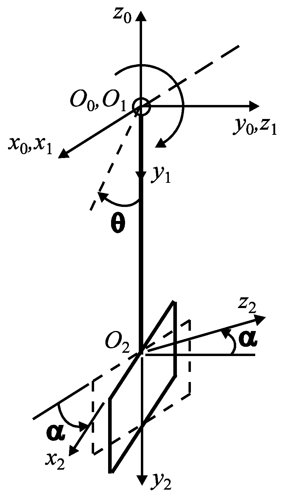
Figure 2.
The steps of the research program.

Figure 3.
Particle interaction with the surface under erosion: (a) successive positions of the particle upon impact with the surface; (b) detail of the trace left by the particle on the impact surface, for an intermediate position.
Figure 3.
Particle interaction with the surface under erosion: (a) successive positions of the particle upon impact with the surface; (b) detail of the trace left by the particle on the impact surface, for an intermediate position.

Figure 4.
Calculation of erosive wear intensity.

Figure 5.
Variation in wear intensity as a function of the angle of incidence, for v0 = 2.5 m/s and friction coefficient µ: 0.25, 0.3, and 0.35 (red, blue, and green in the figures): (a) elastic deformation; (b) plastic deformation.
Figure 5.
Variation in wear intensity as a function of the angle of incidence, for v0 = 2.5 m/s and friction coefficient µ: 0.25, 0.3, and 0.35 (red, blue, and green in the figures): (a) elastic deformation; (b) plastic deformation.

Figure 6.
Variation in wear intensity as a function of impact velocity for µ = 0.25 and impact angle values of α0: 30°, 45°, and 60° (red, blue, and green in the figures): (a) elastic deformation; (b) plastic deformation.
Figure 6.
Variation in wear intensity as a function of impact velocity for µ = 0.25 and impact angle values of α0: 30°, 45°, and 60° (red, blue, and green in the figures): (a) elastic deformation; (b) plastic deformation.
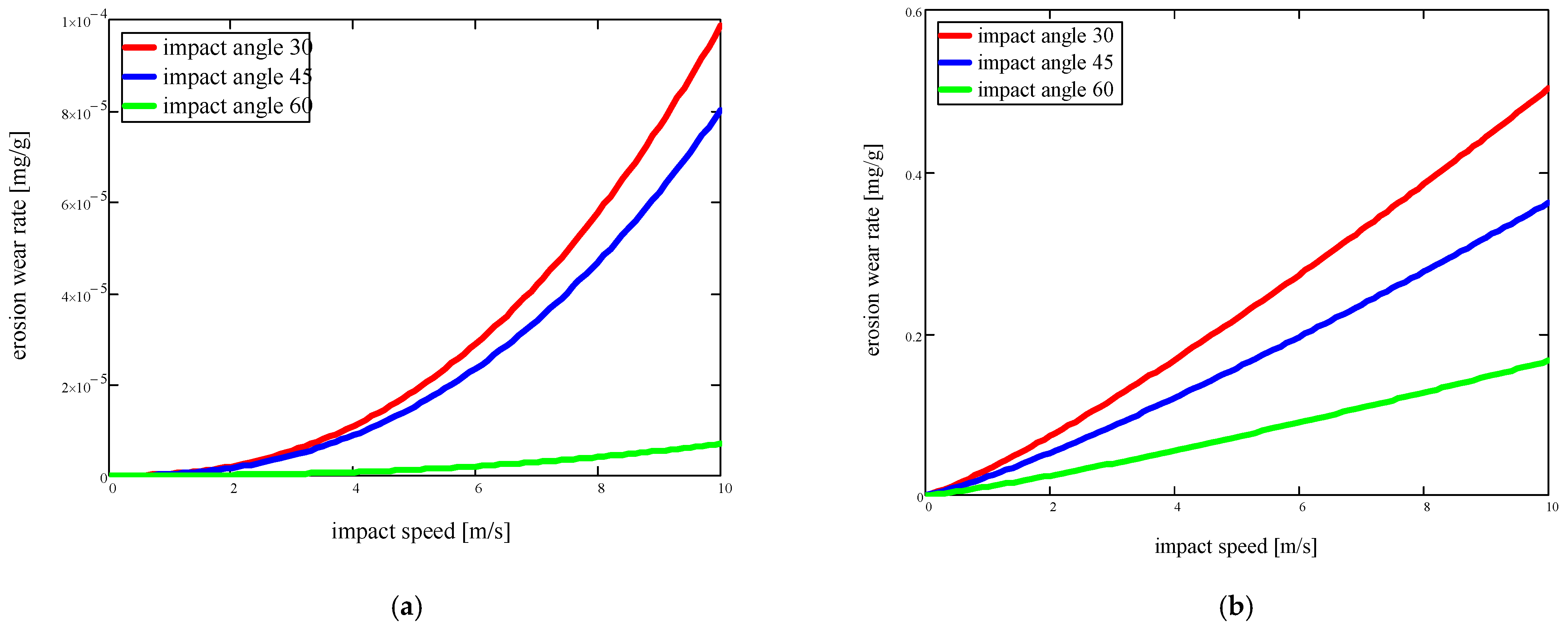
Figure 7.
Variation in wear intensity as a function of friction coefficient, for v0 = 2.5 m/s and impact angle α0: 30°, 45°, and 60° (red, blue, and green in the figures): (a) elastic deformation; (b) plastic deformation.
Figure 7.
Variation in wear intensity as a function of friction coefficient, for v0 = 2.5 m/s and impact angle α0: 30°, 45°, and 60° (red, blue, and green in the figures): (a) elastic deformation; (b) plastic deformation.


Table 1.
Meaning of terms in relationships (1)–(7).
| Symbol | Meaning of Terms |
|---|---|
| the particle–target-surface friction coefficient | |
| angle of incidence | |
| particle velocity | |
| particle radius (spherical particle) | |
| HB | the hardness of the target surface |
| the material density of the target surface | |
| the density of the particle material | |
| the elasticity parameter of the surface material | |
| the tensile strength of the target surface material | |
| the flow resistance of the surface material | |
| e0 | the relative deformation at break through stretching of the surface material |
| k | a constant depending on the assumed breaking assumption |
| n | the number of cycles at which the wear particle occurs—ne—elastic and np—plastic |
| the volume of material deformed by the abrasive particle | |
| the volume of material deformed by a particle | |
| a | the diameter of the contact surface |
| the mass of the used material | |
| the mass of the particles that caused the wear | |
| V | the volume of used material |
| the number of abrasive particles hitting the surface | |
| h | deformation—the distance from the original surface to the deformation trace |
| note | |
| t | friction fatigue parameter [30] |
Table 2.
Specific parameters of the mixer blade.
| Elastic Deformation | Plastic Deformation |
|---|---|
| Em—modulus of elasticity of the surface material—1.85 × 10¹¹ N/m2; vp—Poisson coefficient—0.27 | HB—target surface hardness—490 × 106 N/m2 |
| —angle of incidence—0° ÷ 90°; with three specific values: 30°, 45° and 60° —particle velocity—0.1 ÷ 10 m/s; with a specific velocity of 2.5 m/s —coefficient of friction between particle and material—0.25 ÷ 0.35 —material density of the target surface (cast iron)—7600 kg/m3; —density of particle material (crushed mineral aggregate)—2700 kg/m3; σc—flow resistance of pallet material—350 × 106 N/m2; k—constant depending on the assumed breaking assumption—3; t—friction fatigue parameter—1. | |
Disclaimer/Publisher’s Note: The statements, opinions and data contained in all publications are solely those of the individual author(s) and contributor(s) and not of MDPI and/or the editor(s). MDPI and/or the editor(s) disclaim responsibility for any injury to people or property resulting from any ideas, methods, instructions or products referred to in the content. |
© 2024 by the authors. Licensee MDPI, Basel, Switzerland. This article is an open access article distributed under the terms and conditions of the Creative Commons Attribution (CC BY) license (https://creativecommons.org/licenses/by/4.0/).
Share and Cite
MDPI and ACS Style
Petrescu, M.G.; Popovici, A.-I.; Niță, A.; Isbășoiu, D.; Dumitru, T.; Tănase, M. Modelling Wear Phenomena Specific to Mixer Blades in Concrete Production Plants. Appl. Sci. 2024, 14, 3988. https://doi.org/10.3390/app14103988
AMA Style
Petrescu MG, Popovici A-I, Niță A, Isbășoiu D, Dumitru T, Tănase M. Modelling Wear Phenomena Specific to Mixer Blades in Concrete Production Plants. Applied Sciences. 2024; 14(10):3988. https://doi.org/10.3390/app14103988
Chicago/Turabian StylePetrescu, Marius Gabriel, Aristia-Ioana Popovici, Adrian Niță, Dan Isbășoiu, Teodor Dumitru, and Maria Tănase. 2024. "Modelling Wear Phenomena Specific to Mixer Blades in Concrete Production Plants" Applied Sciences 14, no. 10: 3988. https://doi.org/10.3390/app14103988
Note that from the first issue of 2016, this journal uses article numbers instead of page numbers. See further details here.