
A Two-Port Dual-Band Dual-Circularly-Polarized Dielectric Resonator Antenna

Department of Electrical and Computer Engineering, Sungkyunkwan University, Suwon 440-746, Republic of Korea
*
Author to whom correspondence should be addressed.
Appl. Sci. 2024, 14(10), 4062; https://doi.org/10.3390/app14104062
Submission received: 28 March 2024
/
Revised: 2 May 2024
/
Accepted: 2 May 2024
/
Published: 10 May 2024
(This article belongs to the Section Electrical, Electronics and Communications Engineering)
Abstract
:This paper presents the design of a two-port dual-band dual-circularly-polarized dielectric resonator antenna (DRA). The proposed DRA is formed by stacking two dielectric resonators (DRs) of different shapes, including a hexagonal DR on top and a cross-shaped DR on the bottom. It is designed to resonate at two near-degenerate orthogonal modes of TE111 and TE113, and an aperture-coupled feeding through a cross-like slot is used to achieve dual-band impedance matching simultaneously for right- and left-handed circular polarizations. Tests were conducted on a prototype working in C-band to verify the design concept. The experiment results demonstrate that the proposed DRA has exceptional performance with measured −10 dB reflection bandwidths of 24.4% and 17.4%, 3 dB axial ratio bandwidths of 21.2% and 16.3%, and maximum gains of 5.64 and 8.13 dBic for the lower and upper bands, respectively. Moreover, the measured channel isolation is more than 15.8 dB. The results obtained from the experiments show good agreement with the simulation, and hence, it can be concluded that the proposed DRA is a promising solution that can be used for various wireless communication applications.
1. Introduction
Circularly polarized (CP) antennas have gained considerable attention due to their ability not only to mitigate multipath propagation effects and decrease polarization mismatch loss, but also to suppress Faraday effects caused by the ionosphere [1,2]. Additionally, circularly polarized antennas do not require polarization alignment and are widely used in modern wireless communication, including satellites, unmanned aerial vehicles, wireless sensors, global navigation satellite systems (GNSS), and worldwide microwave access (WiMAX) [3]. This has therefore led to an increase in research on circularly polarized broadband antennas. Besides achieving circular polarization by various techniques, patch antennas are generally low-cost, low-profile, easy to manufacture, and they are used in numerous applications such as satellites, radars, GNSS, and wireless networks. However, microstrip patch antennas have relatively narrow impedance and 3-dB axial ratio (AR) bandwidths [4,5].
Dielectric resonators (DRs) manufactured with a low-loss and high-permittivity material were implemented for the first time as an antenna by Long et al. [6] in 1983. Since then, dielectric resonator antennas (DRAs) have become one of the most popular microwave antennas. Compared to a patch antenna, a DRA has a higher radiation efficiency since no conductor loss occurs. Other attractive features of the DRA include its wide bandwidth, simplicity of excitation, and versatility in shape and material [7,8]. These attractive features make the DRA an excellent antenna candidate for modern wireless communication systems [9]. Circular polarization can be achieved through DRA antennas primarily by modifying either the excitation mechanism or by using a special dielectric resonator (DR). A variety of CP DRAs have been reported so far, including wideband CP DRAs [10,11], broad beamwidth CP DRAs [12,13], dual/multi-band CP DRAs [14,15,16], and so on. Among these CP DRAs, dual-band dual-circularly-polarized (DBDCP) DRAs have gained intensive research interests, especially for satellite communications (SATCOMs) [17,18].
The dual-band antenna offers a low interchannel interference and a reduced size and weight since it works in two frequencies to simultaneously facilitate the uplink and the downlink channels. In addition, the CP rotating sense for each band is opposite to each other, thus further improving the interchannel isolation. However, despite these technical potentials, there are only a few works on DBDCP DRAs [17,18,19,20,21]. A metallic strip-loaded DRA reported in [18] produces a DBDCP performance, but with narrow axial ratio (AR) bandwidths of 5.2% and 4.1%. In [19], a cylindrical DRA excited by a microstrip feedline through an asymmetrical Swastik-shaped aperture was developed, reportedly showing the DBDCP performance of 5.5% for left-handed CP (LHCP) at the lower band (LB) and 8.8% for right-handed CP (RHCP) at the upper band (UB). In another work [20], three pairs of near-degenerate orthogonal modes of the fundamental TE111 and the higher-order TE121 and TE131 of a rectangular DRA were excited simultaneously to yield a large AR bandwidth of 19.8% for LHCP at the LB and 6.1% for RHCP at the UB. The design using a combination of the DRA mode and slot mode in [21] achieved broad AR bandwidths of 27.1% for LHCP in the LB and 12.8% for RHCP in the UB.
In this paper, we propose the design of a two-port DBDCP DRA. The DRA is fed by two 50-Ω microstrip feedlines through a common cross-slot-coupled aperture to resonate at two pairs of near-degenerate orthogonal modes of TE111 and TE113 for simultaneously achieving dual-band impedance matching with RHCP and LHCP performances in the LB and UB, respectively. The antenna performance is first studied using ANSYS HFSS and is then verified through an antenna prototype that works in C-band. Experimental measurements demonstrate that the proposed antenna exhibits broad dual AR bandwidths of more than 16% with dual-CP performance, making it become an excellent candidate for downlink and uplink SATCOM. Simulation and measurement results of reflection coefficients, ARs, gains, and radiation patterns are in reasonable agreement.
The paper is structured as follows: In Section 2, the DRA design and analysis are presented. This includes Section 2.1, which introduces the configuration of the proposed DBDCP DRA with the final optimal parameters. Section 2.2 covers the working mechanism, evolution process, and AR enhancement techniques for the DRA structure, which is designed to achieve dual-band and dual-circular polarization. To obtain optimal performance, parametric studies have been performed, as shown in Section 2.3. The experimental results of the fabricated DRA are summarized and discussed in Section 3. Finally, in Section 4, the proposed DRA is compared with some previously published DBDCP DRAs, and conclusions are drawn.
2. Antenna Design and Analysis
2.1. Antenna Configuration
The geometry of the proposed two-port DBDCP DRA is shown in Figure 1, with the corresponding optimized design parameters listed in Table 1. As illustrated in Figure 1a, the proposed DRA consists of a main DR, a cross-slot-coupled aperture etched on the ground plane, and two 50-Ω microstrip feedlines printed on a dielectric substrate. The main DR is constructed with two stacked DR layers with different shapes, including a top hexagonal DR and a bottom cross-shaped DR, and is made of microwave ceramic material with a dielectric constant of 10.
The hexagonal DR is formed by a square DR of dimension × × with two opposite truncated corners of side length b. The diagonal lengths of the crossed-shaped DR are different ( # ) because tuning appropriately enhances the AR bandwidths at both two operating bands. Two diagonal grooves having size of × are etched on the cross-shaped DR for tuning the AR bandwidth of the LB. A longitudinal groove of size × is engraved on the top of the hexagonal DR for tuning the AR bandwidth of the UB. The main DR is arranged diagonally relative to the x- and y-axes.
The dielectric substrate used here is a Taconic TLY-5 substrate ( = 2.2 and tan = 0.0009) with a size of × and a thickness of = 0.762 mm. The ground plane and the 50-Ω microstrip feedlines are arranged on the top and bottom surfaces of the dielectric substrate, respectively, as displayed in Figure 1b,c. Two feedlines P1 and P2 are used to excite the main DR through the cross-slot-coupled aperture etching, which is constituted of a vertical slot and a horizontal slot etched on the ground plane. The 50-Ω microstrip feedline P1 is bent into a Γ-shaped strip line and coupled through the vertical slot to excite the fundamental TE111 mode of the main DR, whereas the 50-Ω microstrip feedline P2 is connected to a fork-shaped strip line and coupled through the horizontal slot to excite the higher-order TE113 mode of the main DR. Owing to the diagonal arrangement of the main DR, its two operating modes, the fundamental TE111 and the higher-order TE113 modes, split into two pairs of near-degenerate orthogonal modes of near-equal amplitudes and 90° phase difference. The proposed two-port DRA is optimized such that it yields RHCP radiation at the LB with excitation from the feedline P1, while it produces LHCP radiation at the UB with excitation from the feedline P2.
2.2. Working Mechanism
The design goal of this work is to obtain a compact two-port DRA antenna that can generate the dual-band dual-circularly-polarized response. There are two main stages in the design process of the proposed antenna; the first is the realization of the two-port dual-band DRA operating in two close frequency bands, and the second is the realization of circular polarization at each of the operating bands with an opposite sense of circular polarization. The following sections describe in detail the design process of the proposed DBDCP DRA.
Figure 2 shows the evolution toward the dual-band DRA design (first step). We start with a square DR, with a diagonal length of and a height of ( + ), fed by two 50-Ω microstrip feedlines through a cross-slot-coupled aperture etched on the ground plane (Design 1). To realize the dual-band operation, the bottom portion of the square DR is replaced by a cross-shaped DR (Design 2). The simulated results of S-parameters of these two DRAs are illustrated in Figure 3. As observed, Design 1 exhibits a poor impedance matching over the frequency of interest when excited by P1. Meanwhile, when excited by P2, Design 1 produces two impedance bandwidths of 4.35–4.65 GHz and 4.85–5.75 GHz with corresponding dips found at 4.0 GHz and 5.5 GHz.
Using the dielectric waveguide model (DWM) [22], the resonant frequencies of the main square DR are estimated to be 3.88 GHz TE111 and 5.45 GHz TE113. These mode frequencies attained by the DWM closely correspond to those anticipated in simulation. By introducing the cross-shaped DR at the bottom portion, a good impedance matching from 3.35 to 4.25 GHz is achieved in Design 2 when excited by P1 [see Figure 3a]. As a result, Design 2 exhibits dual-band operation. When excited by P1, it operates in the lower frequency band of 3.35–4.25 GHz, and when excited by P2, it operates in the upper frequency band of 5.2–6.2 GHz.
The second step focuses on achieving circular polarization at each operating band with opposite polarization sense. The evolution of this step is shown in Figure 4, and its simulated results of the S-parameters and ARs are presented in Figure 5a and b when P1 and P2 excited, respectively. A pair of symmetrical corner truncations with length b are removed from Design 2 in the first step to build Ant. I. This is a common method for generating two orthogonal degenerate mode pairs of the fundamental TE111 and higher order TE113, responsible for realizing the CP waves. Figure 5 shows that Ant. I achieves dual-band operation with poor AR performance within the −10 dB impedance bandwidth (IBW) at the LB when P1 is excited and a narrow 3 dB AR bandwidth at the UB when P2 is excited.
To improve CP performance, one diagonal length is extended, as illustrated in Figure 4, forming Ant. II (here > ). Simulated results (black dashed line) show that Ant. II achieves a clear improvement in the CP performance for both operating bands. In the UB with P2 excited, the 3 dB AR bandwidth is entirely covered by the −10 dB IBW (see Figure 5b).
However, in the LB with P1 excited, the overlapped 3 dB AR bandwidth/−10 dB IBW is still narrow. To obtain a better AR performance, two diagonal grooves are etched into the cross-shaped DR and a longitudinal groove is engraved into the hexagonal DR from its top, forming the proposed DRA. Clearly observing from the simulated results (red solid line) in Figure 5a,b, the proposed antenna provides a dual-band operation with a good dual-CP performance for both operating bands. For the LB when P1 is excited, the proposed antenna exhibits a −10 dB IBW of 3.35–4.42 GHz, which entirely covers the 3 dB AR bandwidth of 3.52–4.28 GHz. Meanwhile, for the UB with P2 excited, the proposed antenna yields a −10 dB IBW of 5.0–6.0 GHz covering the entire 3 dB AR bandwidth of 5.1–5.95 GHz. This satisfies the design goal of this work.
To clearly understand how the proposed antenna realizes dual-CP operation, the E-field distributions inside the main DR are analyzed. For a clear observation, the diagonal intersecting planes are introduced consisting of x’z’- and y’z’-plane since the main DR is arranged diagonally relative to x- and y-axes. The x’y’-plane is located at the top surface of the main DR.
Figure 6 depicts the simulated results of the E-field distributions for two different angular times at 4.0 GHz with excitation from P1. Two orthogonal modes, namely and modes, are excited simultaneously at 4.0 GHz. Owing to the diagonal arrangement of the main DR, the excitation from the P1 through the cross-slot-coupled aperture effectively excites the fundamental TE111 mode of the main DR and splits it into near-degenerate orthogonal modes. Furthermore, the -field (vector sum of the main E-field distributions) in the x’y’-plane at ωt = 0° is orthogonal to that at ωt = 90° and rotates counter-clockwise as the time t increases. Thus, RHCP is achieved at 4.0 GHz for the LB with P1 excited.
Figure 7 depicts the simulated results of the E-field distributions for two different angular times at 5.5 GHz with excitation from P2. It is also evident that, owing to the diagonal arrangement of the main DR, the excitation from the P2 through the cross-slot-coupled aperture effectively excites the higher-order TE113 mode of the main DR and also splits it into near-degenerate orthogonal and modes. Additionally, the -fields in the x’y’-plane at two orthogonal phases (ωt = 0° and ωt = 90°) are orthogonal to each other, and they rotate 90° clockwise as the time t increases. Thus, LHCP is achieved at 5.5 GHz for the UB with P2 excited. The above analysis demonstrates that the proposed two-port DRA realizes the dual-band operation with dual-CP performance; RHCP at the LB and LHCP at the UB.
2.3. Parametric Study
The parametric analysis of the proposed DBDCP DRA is performed using the ANSYS High Frequency Structure Simulator (HFSS) software version 19.2. The parameters of interest are the width of the corner truncation b, the height of the longitudinal groove , and width of the ground plane , and their effects on the simulated reflection coefficients and ARs are analyzed. During this analysis, one design parameter is studied at a time, while the others remain at optimized values.
Figure 8 shows the effects of varying the width of the corner truncation b on both reflection coefficients and ARs. As shown in Figure 8a, an increment in b shifts the impedance matching of the UB (P2 excited) toward higher frequencies, but this does not have much impact on the impedance matching of the LB (P1 excited). However, by changing the value of b, it is found that the AR performances at both the LB and the UB change dramatically. As indicated in Figure 8b, the 3 dB AR bandwidth of the LB shift toward higher frequencies as b increases. Meanwhile, increasing b from 14.06 mm to 15.06 mm enhance the 3 dB AR bandwidth of the UB, but the AR value increases again to higher than 3 dB as the value of b exceeds 16.06 mm (see Figure 8c).
The impact of variations in the height of the longitudinal groove in the simulated reflection coefficients and ARs are depicted in Figure 9. The performances of the LB and UB are not very sensitive to the variation of the . Increasing the value of slightly shifts the impedance and AR bandwidths of both LB and UB toward higher frequencies. So, an appropriate choice of leads to a maximum overlapped impedance/3 dB AR bandwidths at each band.
The effects of variations in the ground plane size on reflection coefficients and ARs are plotted in Figure 10. It is observed that the impedance matching and 3 dB AR bandwidth move toward lower frequencies with the increase in the value of . Conversely, impedance matching and AR performance of the UB are not very sensitive to the alteration in . This is due to the difference in the feeding configurations from two ports. The feeding configuration in P1 is asymmetrical, and therefore, it is more sensitive with the changing in the ground plane size. Meanwhile, the feeding configuration in P2 is symmetrical.
Based on the parametric study, the optimized values of b, , and are 15.06 mm, 6 mm, and 41 mm, respectively.
3. Experimental Results and Discussion
To corroborate the simulated results, an antenna prototype based on the optimal parameters was made and tested. A picture of the fabricated prototype is shown in Figure 11a. The DR was made of an alumina () ceramic material having a dielectric constant of 10 and a loss tangent of 0.0001. This material has high stability and excellent mechanical properties such as outstanding strength, hardness, heat insulation, oxidation resistance, corrosion resistance, and high-temperature capability [23]. At the same time, the high coefficient of thermal expansion (CTE) () helps minimize the expansion at elevated temperatures to avoid manufacturing tolerances [24]. Therefore, alumina ceramic materials are compatible with computer numerical control (CNC) machining. In addition, with the advancement of current technology, we can completely control and adjust the temperature during the machining process to be compatible with each specific material, ensuring the accuracy of the processed prototype.
A specific-shaped prototype of the main DR is set up with computer-aided design (CAD) software version 23.0, and then fed into a CNC milling system. The milling process will be programmed to operate automatically to accurately remove each part that needs to be cut from the workpiece. The milling machine will include three main axes to position and move the DR workpiece to be machined to different positions along the 3 axes X, Y, and Z. Combined with two 360° rotation axes to machine and cut corners, slots, and grooves of any shape and position on the DR workpiece.
Based on the geometric structure of the main DR in this study, the first step is to cut the workpiece into a cube with dimensions × × ( + ). Next, two opposite truncated diagonal corners of the cube with side length b and height ( + − ) are cut out from the main DR. After that, the four diagonal corners below the DR are removed to form the cross-shaped DR. Finally, two diagonal grooves at the bottom and one longitudinal groove at the top are cut out of the DR workpiece.
The ground plane and the microstrip feedline are mounted on the top and bottom layers of a Taconic TLY-5 dielectric substrate with a dielectric constant = 2.2, a loss tangent tan = 0.0009, and a thickness of 0.76 mm. The ground plane is 41 mm × 41 mm in size. The fabricated DR was attached to the ground plane using epoxy glue. Two SMA connectors were used for the experiment. The inner pins of the SMA connectors are soldered to the feedlines.
An Anritsu MS46122B vector network analyzer was utilized to attain the S-parameters characteristic of the proposed DRA, whereas the radiation properties, such as gains, ARs, and radiation patterns, were measured inside a small RF anechoic chamber in which a dual-band polarized horn antenna was utilized, as shown in Figure 11b. The horn antenna is mounted at the far-field tower and connected to a spectrum analyzer to test and measure the radiation pattern of the antenna under test. The radiation pattern is measured at each 1° step interval in the anechoic chamber with a range of 0–360°, over an operating frequency band of 3.0–6.5 GHz with each frequency step being 0.25 GHz.
Figure 12 depicts a comparison of the measured and simulated S-parameters of the proposed two-port DBDCP DRA. Good agreement is achieved between the measured and simulated results. When P1 is excited, the antenna operates at the LB with a −10 dB IBW of 3.35–4.42 GHz (27.5%) in simulation and a −10 dB IBW of 3.52–4.5 GHz (24.4%) in measurement. Meanwhile, with P2 excited, the antenna operates at the UB with −10 dB IBWs of 5.0–6.0 GHz (18.0%) and 5.14–6.12 GHz (17.4%) in simulation and measurement, respectively. As also observed from Figure 12, the measured port-to-port isolations are more than 15.8 and 18.0 dB within the −10 dB IBWs for the LB and UB, respectively.
Figure 13 depicts a comparison of the measured and simulated results of ARs and realized gains at the boresight direction ( = 0°). With reference to Figure 13a, when P1 is excited (the LB operation), the simulated 3 dB AR bandwidth is 3.52–4.28 GHz (18.7%) while the measured 3 dB AR bandwidth is 3.58–4.43 GHz (21.2%). When P2 is excited (the UB operation), the 3 dB AR bandwidths of 5.1–5.95 GHz (15.0%) and 5.12–6.03 GHz (16.3%) are achieved in the simulation and measurement, respectively. It is worth mentioning that, at each operation band, the measured 3 dB AR bandwidth is entirely covered by the measured −10 dB IBW.
Within the overlapped 3 dB AR bandwidth/−10 dB IBW, the measured gains range from 4.89 to 5.64 dBic for the RHCP (with P1 excited) and 5.81 to 8.13 dBic for the LHCP (with P2 excited) (see Figure 13b). It should be noted that higher gain is provided by the higher order mode, which is appropriate due to the greater electrical magnitude produced at higher frequencies of the DRA. Good agreement is obtained between the experiment and simulation results with some slight discrepancies that are mainly attributed to the unavoidable errors in the fabrication process and experiment.
Figure 14 shows a comparison of the measured and simulated radiation patterns of the proposed two-port DBDCP DRA in the xz-plane ( = 0°) and yz-plane ( = 90°) at 4.0 GHz (P1 excited) and 5.5 GHz (P2 excited). The antenna achieves RHCP characteristic at 4.0 GHz, and the RHCP field is stronger than LHCP field by more than 18.2 dB in the boresight direction, whereas the antenna exhibits LHCP characteristic at 5.5 GHz and the LHCP field is stronger than RHCP field by more than 19.1 dB in the boresight direction.
The key performances of the proposed DRA are compared with other DBDCP DRAs available in the literature, and the results are summarized in Table 2. Regarding this table, the proposed DRA has much broader 3 dB AR bandwidths at both operating bands than those of its counterparts. Furthermore, the proposed DRA uses two-port excitation to achieve dual-band performance on separate channels; thus, it has better features compared to previous designs.
4. Conclusions
A C-band two-port DBDCP DRA was designed, fabricated, and measured. The TE111 and TE113 modes of the designed DRA were utilized to realize dual-band operation and to achieve broadside radiation. The DRA was fed by two 50-Ω microstrip feedlines through a common cross slot to separate its two modes into two pairs of near-degenerate orthogonal modes to achieve DBDCP performance. The experimental results verified that the proposed two-port DRA has a RHCP radiation in the LB (3.58–4.43 GHz) and a LHCP radiation in the UB (5.14–6.03 GHz). The measured gains of the two CP bands were in the ranges of 4.89–5.64 dBic and 5.81–8.13 dBic. Therefore, the proposed two-port DRA with DBDCP performance is a promising candidate for use in SATCOM systems.
Author Contributions
Conceptualization, T.V.T., S.T.-V. and K.C.H.; methodology, T.V.T. and S.T.-V.; software, T.V.T. and S.T.-V.; validation, T.V.T., S.T.-V. and K.C.H.; formal analysis, T.V.T. and S.T.-V.; investigation, T.V.T. and S.T.-V.; resources, T.V.T., K.-Y.L. and Y.Y.; data curation, T.V.T., S.T.-V., K.-Y.L. and Y.Y.; writing—original draft preparation, T.V.T.; writing—review and editing, T.V.T., S.T.-V. and K.C.H.; visualization, T.V.T.; supervision, K.C.H.; project administration, K.C.H. All authors have read and agreed to the published version of the manuscript.
Funding
This work was supported by Institute of Information & Communications Technology Planning & Evaluation (IITP) grant funded by the Korea government Ministry of Science and Information & Communication Technologies (MSIT) (No. 2020-0-00261, Development of low power/low delay/self-power suppliable RF simultaneous information and power transfer system and stretchable electronic epineurium for wireless nerve bypass implementation).
Institutional Review Board Statement
Not applicable.
Informed Consent Statement
Not applicable.
Data Availability Statement
All data have been included in study.
Conflicts of Interest
The authors declare no conflicts of interest.
References
- Choi, D.-S.; Choi, Y.-S.; Lee, H.-J.; Lee, S.-I.; Woo, J.-M. Design of a dual-mode waveguide CP antenna with a symmetric beamwidth using short stub for low-orbit satellite TC&R. J. Electromagn. Eng. Sci. 2023, 23, 398–404. [Google Scholar]
- Sung, Y. A dual orthogonal fed monopole antenna for circular polarization diversity. J. Electromagn. Eng. Sci. 2022, 22, 283–290. [Google Scholar] [CrossRef]
- Mekki, K.; Necibi, O.; Lakhdhar, S.; Gharsallah, A. A UHF/UWB monopole antenna design process integrated in an RFID reader board. J. Electromagn. Eng. Sci. 2022, 22, 479–487. [Google Scholar] [CrossRef]
- Gao, S.; Zhu, F. Circularly Polarized Antennas; Wiley: West Sussex, UK, 2014. [Google Scholar]
- Nguyen, T.D.; Choi, J.H.; Jung, C.W. Optically transparent patch antennas using saltwater for WLAN applications. J. Electromagn. Eng. Sci. 2022, 22, 609–615. [Google Scholar] [CrossRef]
- Long, S.; McAllister, M.; Shen, L. The resonant cylindrical dielectric cavity antenna. IEEE Trans. Antennas Propag. 1983, 3, 406–412. [Google Scholar] [CrossRef]
- Luk, K.M.; Leung, K.W. Dielectric Resonator Antennas; Research Studies Press: Baldock, UK, 2003. [Google Scholar]
- Park, S.-J.; Park, J.-H.; Lee, M.-Q. Millimeter-Wave monopulse filtenna array with directive dielectric resonators. J. Electromagn. Eng. Sci. 2023, 23, 81–89. [Google Scholar] [CrossRef]
- Iqbal, J.; Illahi, U.; Sulaiman, M.I.; Alam, M.M.; Su’ud, M.M.; Yasin, M.N.M.; Jamaluddin, M.H. Bandwidth enhancement and generation of CP by using parasitic patch on rectangular DRA for wireless applications. IEEE Access 2019, 7, 94365–94372. [Google Scholar] [CrossRef]
- Trinh-Van, S.; Yang, Y.; Lee, K.-Y.; Hwang, K.C. Single-fed circularly polarized dielectric resonator antenna with an enhanced axial ratio bandwidth and enhanced gain. IEEE Access 2020, 8, 41045–41052. [Google Scholar] [CrossRef]
- Xia, Z.-X.; Leung, K.W. 3-D-printed wideband circularly polarized dielectric resonator antenna with two printing materials. IEEE Trans. Antennas Propag. 2022, 70, 5971–5976. [Google Scholar] [CrossRef]
- Illahi, U.; Iqbal, J.; Sulaiman, M.I.; Alam, M.M.; Su’ud, M.M.; Jamaluddin, M.H. Singly-fed rectangular dielectric resonator antenna with a wide circular polarization bandwidth and beamwidth for WiMAX/Satellite applications. IEEE Access 2019, 7, 66206–66214. [Google Scholar] [CrossRef]
- Zhong, Z.; Zhang, X.; Liang, J.J.; Han, C.Z.; Fan, M.L.; Huang, G.L.; Xu, W.; Yuan, T. A compact dual-band circularly polarized antenna with wide axial-ratio beamwidth for vehicle GPS satellite navigation application. IEEE Trans. Veh. Technol. 2019, 68, 8683–8692. [Google Scholar] [CrossRef]
- Altaf, A.; Seo, M. Triple-band dual-sense circularly polarized hybrid dielectric resonator antenna. Sensors 2018, 18, 3899. [Google Scholar] [CrossRef] [PubMed]
- Wang, X.-C.; Sun, L.; Lu, X.-L.; Liang, S.; Lu, W.-Z. Single-feed dual-band circularly polarized dielectric resonator antenna for CNSS applications. IEEE Antennas Wireless Propag. Lett. 2017, 65, 4283–4287. [Google Scholar] [CrossRef]
- Zhou, Y.-D.; Jiao, Y.-C.; Weng, Z.-B.; Ni, T. A novel single-fed wide dual-band circularly polarized dielectric resonator antenna. IEEE Antennas Wirel. Propag. Lett. 2016, 15, 930–933. [Google Scholar] [CrossRef]
- Sharma, A.; Tripathi, D.K.; Das, G.; Gangwar, R.K. 3-D printed dual-band, dual-sense circularly polarized dielectric resonator antenna with a bandstop filtering response using planar via-free D-CRLH feeding network. AEU Int. J. Electron. Commun. 2023, 169, 154760. [Google Scholar]
- Xu, H.; Chen, Z.; Liu, H.; Chang, L.; Huang, T.; Ye, S.; Zhang, L.; Du, C. Single-fed dual-circularly polarized stacked dielectric resonator antenna for K/Ka-band UAV satellite communications. IEEE Trans. Veh. Technol. 2022, 71, 4449–4453. [Google Scholar] [CrossRef]
- Sharma, A.; Tripathi, D.K.; Das, G.; Gangwar, R.K. Novel asymmetrical swastik-shaped aperture coupled cylindrical dielectric resonator antenna with dual-band and dual-sense circular polarization characteristics. Microw. Opt. Technol. Lett. 2019, 61, 405–411. [Google Scholar] [CrossRef]
- Zhang, M.; Li, B.; Lv, X. Cross-slot-coupled wide dual-band circularly polarized rectangular dielectric resonator antenna. IEEE Antennas Wirel. Propag. Lett. 2014, 13, 532–535. [Google Scholar] [CrossRef]
- Zhao, Z.; Ren, J.; Liu, Z.; Yin, Y. Wideband dual-feed, dual-sense circularly polarized dielectric resonantor antenna. IEEE Trans. Antennas Propag. 2020, 68, 7785–7793. [Google Scholar] [CrossRef]
- Kumar Mongia, R.; Ittipiboon, A. Theoretical and experimental investigations on rectangular dielectric resonator antennas. IEEE Trans. Antennas Propag. 1997, 45, 1348–1356. [Google Scholar] [CrossRef]
- Pan, H.; Li, Y.-P.; Zhang, H.-F. Design and optimization of circularly polarized dielectric resonator antenna array based on Al2O3 ceramic. Alex. Eng. J. 2023, 12, 154–166. [Google Scholar] [CrossRef]
- Besisa, N.H.; Besisa, D.H.; Ewais, E.M. Processing of high temperature alumina/aluminum titanate ceramic composites from clean sources. Sci. Rep. 2022, 12, 5957. [Google Scholar] [CrossRef] [PubMed]
Figure 1.
Configuration of the proposed two-port DBDCP DRA. (a) Disassembled view, (b) upper view of the substrate, and (c) bottom view of the substrate.
Figure 1.
Configuration of the proposed two-port DBDCP DRA. (a) Disassembled view, (b) upper view of the substrate, and (c) bottom view of the substrate.
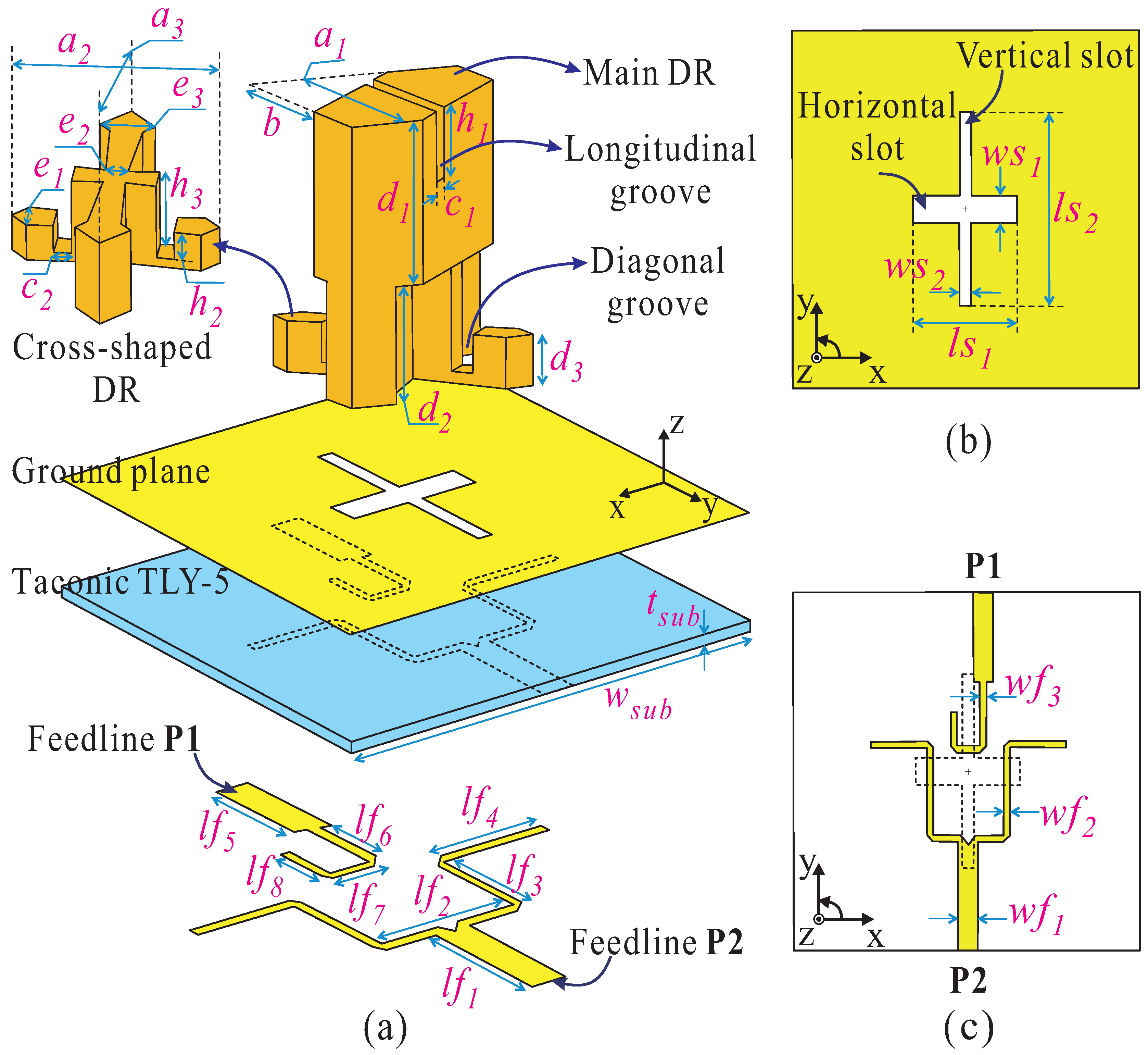
Figure 2.
Evolution toward to the dual-band DRA design.

Figure 3.
Simulated results of (a) and (b) of the dual-band DRA design.

Figure 4.
Evolution toward to the proposed DBDCP DRA.
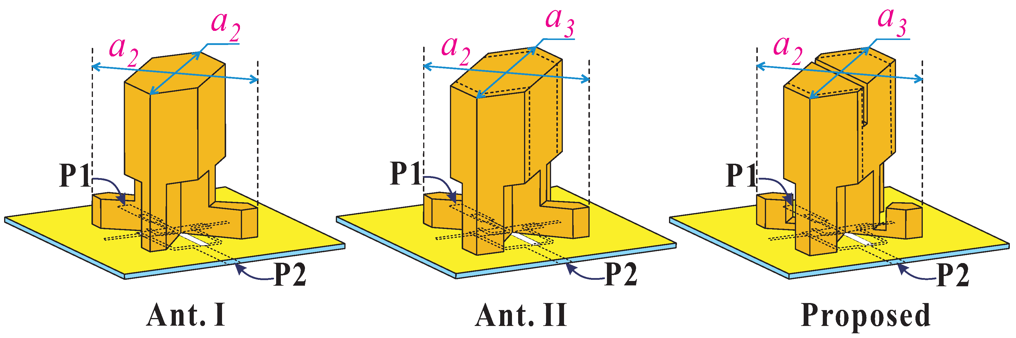
Figure 5.
Simulated results of (a) and AR when P1 excited and (b) and AR when P2 excited of the proposed DBDCP DRA.
Figure 5.
Simulated results of (a) and AR when P1 excited and (b) and AR when P2 excited of the proposed DBDCP DRA.
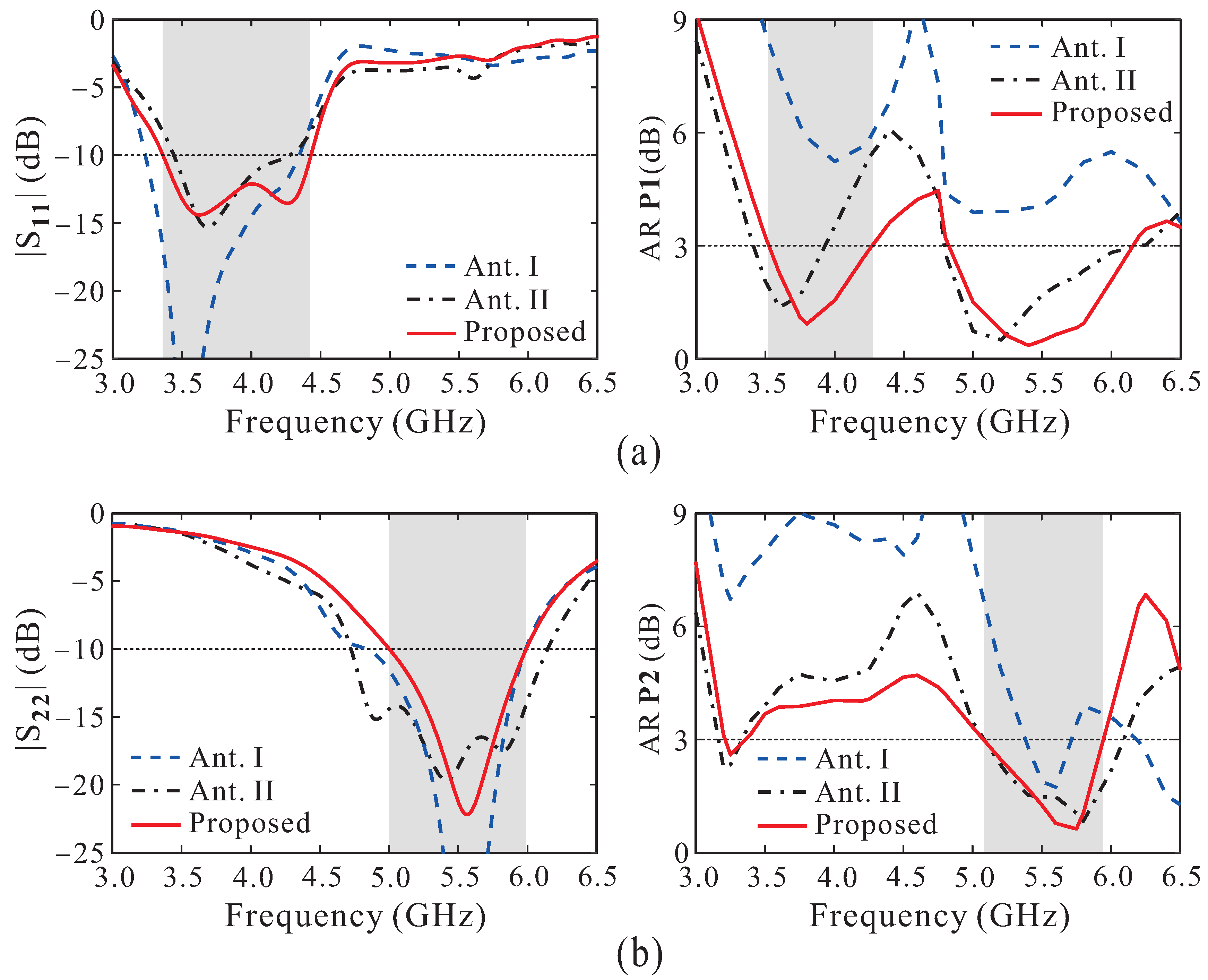
Figure 6.
Simulated E-field distributions inside proposed DRA at 4.0 GHz when excited by P1.

Figure 7.
Simulated E-field distributions inside proposed DRA at 5.5 GHz when excited by P2.

Figure 8.
Simulated results of (a) reflection coefficient, (b) AR when P1 excited and (c) AR when P2 excited for the proposed DBDCP in terms of b.
Figure 8.
Simulated results of (a) reflection coefficient, (b) AR when P1 excited and (c) AR when P2 excited for the proposed DBDCP in terms of b.

Figure 9.
Simulated results of (a) reflection coefficient, (b) AR when P1 excited and (c) AR when P2 excited for the proposed DBDCP in terms of .
Figure 9.
Simulated results of (a) reflection coefficient, (b) AR when P1 excited and (c) AR when P2 excited for the proposed DBDCP in terms of .

Figure 10.
Simulated results of (a) reflection coefficient, (b) AR when P1 excited and (c) AR when P2 excited for the proposed DBDCP in terms of .
Figure 10.
Simulated results of (a) reflection coefficient, (b) AR when P1 excited and (c) AR when P2 excited for the proposed DBDCP in terms of .

Figure 11.
Photographs of the (a) fabricated prototype and (b) radiation pattern measurement setup.

Figure 12.
Measured and simulated S-parameters characteristic of the proposed two-port DBDCP DRA.
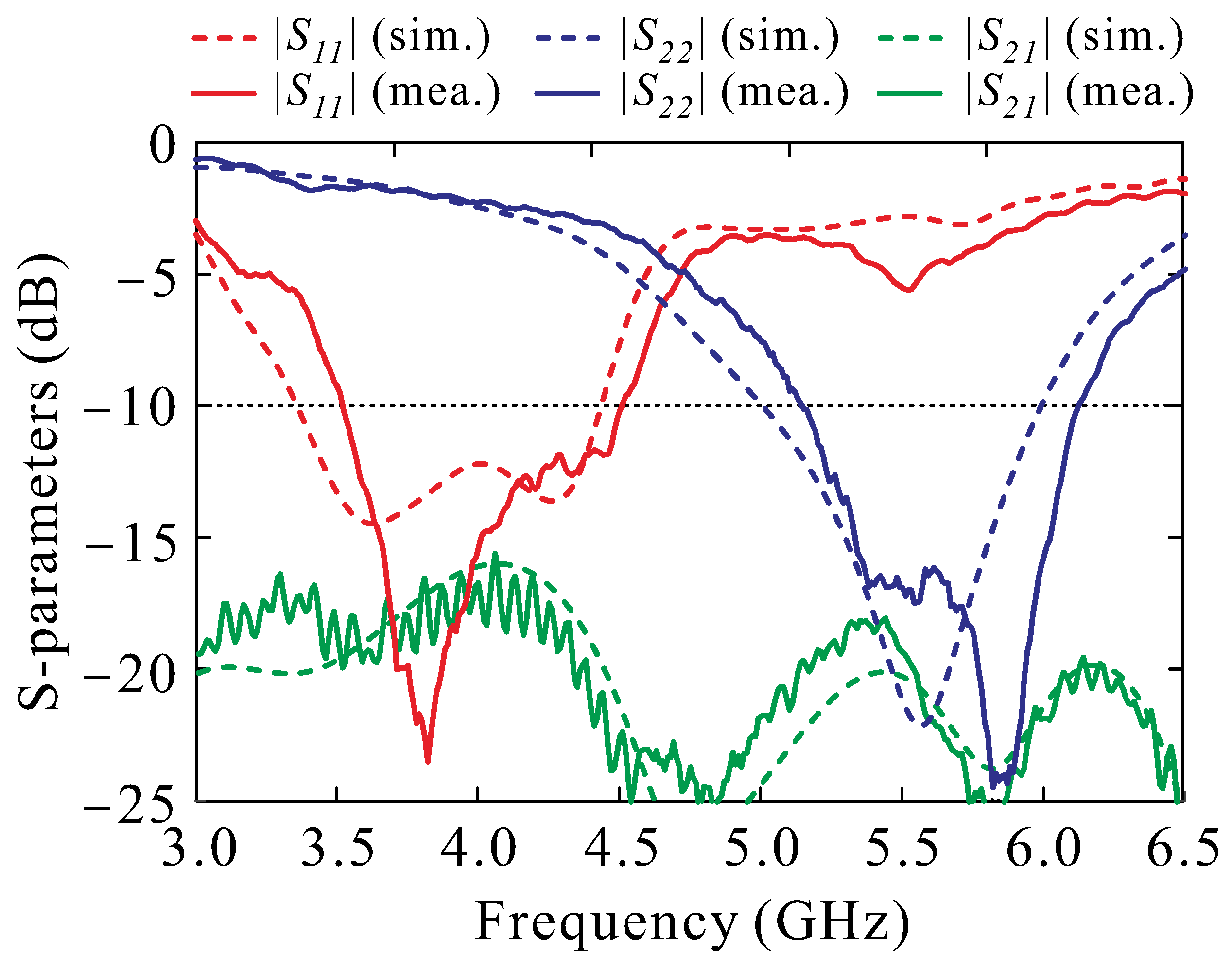
Figure 13.
Measured and simulated (a) ARs and (b) gains of the proposed two-port DBDCP DRA.

Figure 14.
Measured and simulated normalized radiation patterns of the proposed two-port DBDCP DRA at (a) 4.0 GHz, fed by P1 and (b) 5.5 GHz, fed by P2 (Solid lines: measurement. Dotted lines: simulation).
Figure 14.
Measured and simulated normalized radiation patterns of the proposed two-port DBDCP DRA at (a) 4.0 GHz, fed by P1 and (b) 5.5 GHz, fed by P2 (Solid lines: measurement. Dotted lines: simulation).


Table 1.
Optimized parameters of the proposed two-port DBDCP DRA.
| Parameter | Value | Parameter | Value | Parameter | Value |
|---|---|---|---|---|---|
| 22.71 | 7.07 | 4.7 | |||
| 26.46 | 6 | 12.4 | |||
| 32.11 | 8.9 | 22.3 | |||
| b | 15.06 | 3.41 | 3.2 | ||
| 2.26 | 12.49 | 1.3 | |||
| 2.25 | 8.45 | 2.3 | |||
| 19.49 | 10.86 | 0.65 | |||
| 4.41 | 7.31 | 0.73 | |||
| 14 | 10.28 | 0.762 | |||
| 4.24 | 7.33 | 41 | |||
| 2.83 | 2.75 |
Unit: mm.
Table 2.
Performance comparison with other DBDCP DRAs.
| Ref. | IBW | ARBW | Polarization | Peak Gain | Frequency Ratio |
|---|---|---|---|---|---|
| [%] | [%] | [dBic] | |||
| [12] | 23.6 | 9.3 | LHCP | 5.9 | 1.53 |
| 5.3 | 3.6 | RHCP | 4.7 | ||
| [13] | 6.4 | 5.2 | RHCP | 6.6 | 1.36 |
| 12.8 | 4.1 | LHCP | 8.2 | ||
| [14] | 10.75 | 5.5 | LHCP | 3.4 | 1.32 |
| 16.79 | 8.8 | RHCP | 5.8 | ||
| [15] | 27.7 | 15.7 | LHCP | 2.3 | 1.25 |
| 8.5 | 6.0 | RHCP | 4.3 | ||
| [16] | 30.3 | 12.6 | LHCP | 5.0 | 1.38 |
| 4.4 | 11.9 | RHCP | 2.4 | ||
| Proposed | 24.4 | 21.2 | RHCP | 5.64 | 1.51 |
| 17.4 | 16.3 | LHCP | 8.13 |
IBW: Impedance bandwidth. ARBW: Axial ratio bandwidth.
Disclaimer/Publisher’s Note: The statements, opinions and data contained in all publications are solely those of the individual author(s) and contributor(s) and not of MDPI and/or the editor(s). MDPI and/or the editor(s) disclaim responsibility for any injury to people or property resulting from any ideas, methods, instructions or products referred to in the content. |
© 2024 by the authors. Licensee MDPI, Basel, Switzerland. This article is an open access article distributed under the terms and conditions of the Creative Commons Attribution (CC BY) license (https://creativecommons.org/licenses/by/4.0/).
Share and Cite
MDPI and ACS Style
Van Trinh, T.; Trinh-Van, S.; Lee, K.-Y.; Yang, Y.; Hwang, K.C. A Two-Port Dual-Band Dual-Circularly-Polarized Dielectric Resonator Antenna. Appl. Sci. 2024, 14, 4062. https://doi.org/10.3390/app14104062
AMA Style
Van Trinh T, Trinh-Van S, Lee K-Y, Yang Y, Hwang KC. A Two-Port Dual-Band Dual-Circularly-Polarized Dielectric Resonator Antenna. Applied Sciences. 2024; 14(10):4062. https://doi.org/10.3390/app14104062
Chicago/Turabian StyleVan Trinh, Thai, Son Trinh-Van, Kang-Yoon Lee, Younggoo Yang, and Keum Cheol Hwang. 2024. "A Two-Port Dual-Band Dual-Circularly-Polarized Dielectric Resonator Antenna" Applied Sciences 14, no. 10: 4062. https://doi.org/10.3390/app14104062
Note that from the first issue of 2016, this journal uses article numbers instead of page numbers. See further details here.