
Deformation of Existing Shield Tunnel Adjacent to Deep Excavations: Simulation and Monitoring Analysis
Key Laboratory of Road and Traffic Engineering of Ministry of Education, Tongji University, Shanghai 201804, China
*
Author to whom correspondence should be addressed.
Appl. Sci. 2024, 14(10), 4153; https://doi.org/10.3390/app14104153
Submission received: 19 March 2024
/
Revised: 26 April 2024
/
Accepted: 1 May 2024
/
Published: 14 May 2024
(This article belongs to the Special Issue Technical Challenges and Countermeasures for the Construction, Operation and Maintenance of Geotechnical and Underground Engineering for Rail Transit)
Abstract
:Deep excavations near subway tunnels can induce deformation, necessitating a comprehensive investigation into causal factors and mitigation strategies. Field measurements were conducted to assess both vertical and horizontal displacements of existing tunnels near a deep excavation in Shenzhen. Utilizing a validated three-dimensional finite element model that considers structure−strata interactions, this study analyzes tunnel displacements, ground movements, diaphragm wall impacts and the sensitivity of enclosure structure parameters. The results indicate that tunnel deformation correlates with enclosure structure deformation, particularly near the center of the pit. Moreover, shallow soil excavation significantly affects the vertical displacement of shallow-buried tunnels. However, the design parameters of the existing enclosure structures inadequately limit tunnel displacement. Therefore, it is crucial to intensify vertical displacement monitoring in shallow tunnels during early excavation stages and to enhance horizontal displacement monitoring during later phases. Implementing measures such as optimizing central support design or retaining soil at the pit bottom helps control maximum horizontal displacement. While support stiffness plays a greater role than retaining wall thickness, its impact on deep excavation projects is limited.
1. Introduction
Urban subway networks are expanding, leading to the emergence of rail transit hubs that interconnect various lines. Hub stations, with their complex layouts and multiple intersections, significantly influence nearby tunnels during deep excavation activities. Excavation of the foundation pit disrupts the equilibrium of the surrounding soil, causing deformation and displacement, particularly in tunnels parallel to the pit. Significant tunnel deformation can result in cracks and leaks, thereby jeopardizing rail transit safety; therefore, precise analysis and control of the impact of hub construction on adjacent tunnels are crucial. In the field of underground structures and geotechnical engineering, the influence of foundation pit excavation on surrounding tunnels has long captivated researchers. Scholars globally have explored this issue from various angles, including theoretical analysis [1,2], numerical simulation [3,4,5], physical model experiments [6,7], and field monitoring [8,9,10]. Zhang and Wei [11,12] proposed a sidewall unloading model that considers the deformation of retaining structures during excavation, providing essential theoretical support and validating the reliability of their approach. Li [13] offered specific recommendations for optimizing excavation methods through numerical simulations of the divided alternate excavation method, advancing engineering practices. Jin [14] analyzed extensive monitoring data and proposed empirical equations to predict the deformation of existing tunnels, providing valuable insights regarding risk assessment and control in practical engineering. Chen [15] investigated the effects of large excavations in soft soils on existing metro tunnels and proposed effective protective measures, offering practical recommendations for underground engineering safety. Liu and Ye [16,17] conducted thorough studies on the stability of tunnels under excavation through numerical simulations and finite element analyses, suggesting corresponding safety evaluations and protective measures. Liu and Fu [18,19] examined the effects of different support schemes on nearby tunnel deformations through numerical simulations and theoretical calculations, providing technical guidance for engineering practices. Ter-Martirosyan and Lu [5,20] derived regression equations and conducted impact factor analyses to predict tunnel deformations through geological monitoring and finite element modeling, providing important reference points for engineering design and construction. Liu and Xie [21,22] conducted laboratory experiments and numerical simulations, respectively, illustrating the effectiveness of a grouting layer in enhancing the lining resistance to deformation, particularly when tunnels pass through settlement-sensitive zones. Previous research has established a solid foundation for understanding how foundation pit construction impacts tunnel deformation; however, it is crucial to acknowledge the regional and uncertain nature of foundation pit engineering. The impact of different support systems on nearby buildings and structures varies, especially for lateral tunnels close to the site. This paper aims to compare and analyze field monitoring data and numerical simulation results from a hub foundation pit project in Shenzhen, seeking to explore how adjacent lateral foundation pit excavation affects existing tunnels in the project area while analyzing the sensitivity of retaining structure parameters and providing a basis for understanding the impact of foundation pit excavation.
2. Engineering Background
The project is situated in the central urban area of Shenzhen, where the terrain is relatively flat. Geological drilling at the site has revealed the main geological layers, which from top to bottom, include unconsolidated soil, unconsolidated soil (gravel), sand and gravel, gravelly cohesive soil and weathered granite. The tunnel structure’s bottom plate is primarily located within gravelly cohesive soil. The site’s groundwater is classified into two types, which are loose rock pore water, predominantly found in the fluvial and alluvial sand layers and residual gravelly cohesive soil layers, and bedrock fissure water, which is primarily found in blocky, strongly and moderately weathered fracture zones. This water type exhibits slight compressibility, is chiefly replenished by pore water, and is expelled through underground runoff. An existing subway tunnel is adjacent to the site, with the right-side tunnel situated 3.9 m from the north side of the foundation pit. The spatial relationship between the foundation pit and the existing tunnel is illustrated in Figure 1.
During operations, the subway tunnel strictly controls structural deformations, such as settlement, horizontal displacement, and differential deformation. Considering factors such as engineering geology, hydrogeology, and environmental impacts, the foundation pit utilizes a support system that includes a 1000/1200 mm-thick diaphragm wall with internal bracing. Concrete supports are placed at both the north and south ends of the pit, with six concrete supports situated at each end. In the standard section, the first and fifth supports are concrete, with the second, third, fourth, and sixth supports comprising steel pipes with a diameter of 800 mm and a thickness of 20 mm.
Automated monitoring sections are positioned at 5 and 10 m intervals along the alignment of the tunnel section, with intensified monitoring at Area 1. Each section contains five monitoring points to track deformations of the tunnel vault, haunch, and bottom plate. Figure 2 shows the foundation pit profile and the layout of monitoring points. The deformation monitoring control indicators for this project are detailed in Table 1.
3. Numerical Simulation
3.1. Description of the FE Model
Using the finite element method, a numerical model was developed to simulate the interaction between the strata, support, and structure of the project. This three-dimensional model, as depicted in Figure 3, spans 380 m in length, 200 m in width, and 50 m in height, conforming to the construction scheme and boundary effects. The existing tunnel’s right line is located 3.9 m north of the foundation pit and at a depth of 9.3 m. The model features increased mesh density in deformation-sensitive areas such as tunnel structures, retaining walls, and the surrounding strata. The displacement boundary conditions, as illustrated in Figure 3, include no horizontal displacement along all vertical mesh boundaries (in order to simulate a real-world scenario of only settlement deformation without lateral soil movement), no vertical or horizontal displacement at the bottom boundary of the mesh (which mimics a stable bedrock scenario), as well as freedom for displacement along the top boundary. Figure 4 details the structural features of the support system and the specific placement of supports in sections a-a and b-b.
The numerical simulation proceeded as follows: Initially, the geo-stress was balanced, and then the model was rebalanced following the sequential construction of tunnel segments. Subsequently, the retaining structure, which includes the diaphragm wall, grid columns, and pile foundations, was built. The soil was then excavated using the birth-and-death element method and segmented into six layers, as depicted in Figure 2. The excavation continued progressively with support until the bottom of the pit was reached. Throughout the simulation, deformations at the tunnel vault and haunch positions were continuously monitored.
3.2. Model Parameters
The model for the strata utilizes the modified Mohr−Coulomb model, which is an optimized version of the traditional Mohr−Coulomb model incorporating soil hardening characteristics. This model allows the elastic modulus to vary based on loading and unloading conditions, making it highly suitable for simulating foundation pit excavations [23]. The parameters of the soil used in this study are detailed in Table 2 and all derived from laboratory tests. Due to the relatively minor presence of groundwater at the site and preemptive waterproofing measures, groundwater seepage was not incorporated into the numerical model.
Considering the substantially higher strength of concrete and steel compared to soil materials, using elastic materials [15,24] for the simulation is justified. Both the diaphragm wall and internal supports are modeled using elastic parameters based on their actual properties. The tunnel lining is represented as an orthotropic linear elastic material, with detailed parameters being listed in Table 3. The geometric shape of the grid columns is complex; therefore, equivalent cross-sectional dimensions were calculated based on stiffness equivalency. Considering the decrease in stiffness resulting from the joints [25], the rigidity ratios for the lining were adjusted to 0.7 [15,26] in the circumferential direction and 0.1 [27] in the longitudinal direction, resulting in elastic moduli of 24.15 GPa circumferentially and 3.45 GPa longitudinally. Table 3 displays the parameters of the structure and support models.
3.3. Model Validation
During the excavation of the foundation pit, the displacements of the existing tunnel vault and haunch were closely monitored. Field monitoring data from the right-side tunnel, collected after the completion of the excavation, were compared with corresponding numerical simulation results. This comparison allowed for the validation of the numerical model’s rationality by correlating the displacement values of different tunnel sections in the model with the actual measurements.
Figure 5 illustrates the vertical displacement of the right-side tunnel vault, comparing results from both the numerical simulation and field monitoring. Positive values represent uplift, while negative values represent settlement along the vertical axis. The east side of the tunnel corresponds to the existing station, with the horizontal axis representing the distance from the station’s opening. The displacement trend indicates that, upon completion of the foundation pit excavation, the maximum accumulated vertical displacement predominantly occurs at the northern end of the hub area, forming a “spoon” shape along the tunnel axis. This pattern highlights the significant disturbance impacts of the excavation on the tunnel within the hub area. Near the northern end, the increase in the curve’s slope suggests a localized impact from the excavation. The maximum measured vertical settlement is 13 mm, whereas the maximum settlement in the numerical simulation is 8.6 mm, indicating a relatively close agreement between the two results and validating the reliability of the model. However, due to complex factors, such as additional site excavation and dewatering during actual construction, the vertical displacement curve from the simulation in Figure 5 does not perfectly align with the measured data. Nonetheless, both sources exhibit relatively consistent trends in displacement changes, especially near the northern end of the hub area, where the data align more closely.
Figure 6 presents the horizontal displacement of the right-side tunnel, comparing numerical simulation and actual monitoring results. Positive values indicate movement toward the pit. The data show a consistent trend in the horizontal displacement of the tunnel haunch, with greater displacement near the northern end of the hub area and lesser displacement farther away. The maximum values observed in the field were 21 mm, while the simulation showed a maximum of 15.29 mm, with both occurring at the northern end, underscoring the localized impact of the excavation. The simulated horizontal displacement values are generally lower than those measured, likely influenced by other construction activities at the site. However, the close approximation and consistency between the measured and simulated results affirm the model’s reliability.
4. Simulation Results
4.1. Tunnel Vertical Displacement
Figure 7 illustrates the vertical displacement distribution of the existing tunnel vault during the foundation pit excavation, showing that the excavation process disturbs the foundation pit, leading to vertical settlement in the tunnels nearby. A notable increase in the rate of vertical settlement is observed within a specific range of the foundation pit, delineating a significant zone of vertical displacement disturbance.
Vertical displacement is highly sensitive to disturbances from excavation, even with shallow soil excavation. Throughout the excavation, maximum displacement values are primarily concentrated in the central area of the pit. As the excavation depth increases, the increase in vertical displacement is constrained, peaking at 8.60 mm. Significant disturbances to the tunnel’s vertical displacement occur at a depth of 6 m during the excavation of the first soil layer. This disturbance results from the cantilevered distribution of the retaining structure’s displacement, with the maximum displacement occurring at the top. The loose soil behind the retaining structure further contributes to the tunnel’s vertical displacement; therefore, it is crucial to enhance monitoring and early warning systems for vertical displacement in shallow-buried tunnels during the early stages of pit construction. Although the excavation depths of the first three soil layers do not exceed the tunnel’s arch bottom, causing no significant changes in tunnel vertical displacement, once the excavation depth surpasses the arch bottom, the vertical displacement notably increases.
4.2. Tunnel Horizontal Displacement
Figure 8 presents the horizontal displacement distribution of the existing tunnel vault during the foundation pit excavation, showing that all tunnels move toward the pit. A significant increase in the rate of horizontal displacement is observed within a specific range of the foundation pit, indicating a zone of considerable disturbance. The depth of soil excavation significantly impacts the horizontal displacement of the tunnel, with deeper excavations causing greater displacement. This effect is due to the deep soil excavation pushing the lower and middle parts of the enclosure structure into the pit, thereby moving the tunnel further toward the pit. Given the tunnel’s proximity to the pit, enhancing the horizontal displacement monitoring and early warning systems during the middle and late stages of pit construction is essential.
4.3. Ground Displacement
Figure 9a shows the vertical displacement distribution of the ground surface along the B-B section (Figure 3) during the foundation pit excavation. Shallow excavation results in maximum vertical displacement at the pit’s edge. As excavation continues, the location of maximum vertical displacement gradually shifts outward, forming a settlement trough pattern. This shift occurs primarily due to the deformation mode of the retaining structure influencing surface displacement. Initially, with shallow excavation, the retaining structure operates in a cantilevered mode. As excavation deepens, the structure transitions to a compound mode, causing the outer soil to move inward towards the middle of the retaining structure, leading to ground displacement.
Figure 9b shows the vertical displacement distribution of the ground surface along the A-A section (Figure 3) during the foundation pit excavation. Notably, both sections B-B and A-A exhibit traditional settlement trough deformation patterns, though there are differences within a certain range between them. This discrepancy is attributed to the interaction between the existing tunnel and the surrounding soil, resulting in the significant vertical settlement of the tunnel. As a result, the maximum settlement value in section A occurs directly above the existing tunnel, highlighting the differential settlement patterns between the B and A sections and underscoring the interaction between the tunnel structure and the soil. Figure 9c depicts the surface displacement cloud after the completion of the excavation, illustrating the significant disturbance to the surrounding strata caused by the excavation.
5. Analysis of Factors Affecting Tunnel Deformation
In this section, a time-series analysis of field measurements from the A-A section is performed to explore the factors contributing to tunnel displacement. Furthermore, numerical simulations are employed to examine the impact of the foundation pit’s retaining structure on tunnel deformation. Additionally, a sensitivity analysis of the retaining structure parameters is conducted to refine the design and enhance control over tunnel deformation.
5.1. Time Series Analysis of Field Measurements
Throughout construction, an extensive automated monitoring system was implemented to assess the effects of the foundation pit construction on the tunnel. The construction timeline was divided into four stages: ① earthwork excavation; ② support removal, interspersed with the construction of the negative three-layer middle plate of the foundation pit; ③ encompasses various layer floors and middle plate construction; ④ completion of the North Hub project, alongside construction activities in the adjacent area. Figure 10 illustrates these key construction steps.
The previous analysis emphasizes notable displacement near the center of the adjacent foundation pit. Accordingly, Figure 11 shows the horizontal and vertical displacements at Monitoring Point 1, which is located in the tunnel section at the pit’s center. Initial disturbances from constructing the diaphragm wall resulted in significant tunnel deformation. At the start of excavation, the tunnel experienced a horizontal displacement of 13.8 mm and a vertical displacement of −5 mm. In Stage ①, both horizontal and vertical displacements progressively increased with excavation, demonstrating a linear relationship with the excavation process. During Stage ②, while constructing the negative three-layer middle plate, tunnel displacements remained relatively stable. However, displacements increased further during support removal, particularly during the removal of the fifth support, when the vertical displacement rate surged significantly due to the decreased rigidity of the concrete support after removal. In Stage ③, the vertical displacement of the tunnel remained stable, while there was a slight increase in horizontal displacement. Once the floor construction was completed, the foundation pit stabilized. In Stage ④, tunnel displacement initially exhibited a slow upward trend, which then decreased until stabilization. The excavation of the foundation pit was the primary factor causing displacement in the adjacent tunnel. However, the impact of support removal, particularly the removal of the high-rigidity concrete support, was significant. After completing the negative one-layer middle plate construction, the foundation pit and tunnel displacement stabilized.
Figure 11 shows that both horizontal and vertical displacements of the tunnel exceed the deformation monitoring control limit (10 mm), triggering several red alert notifications. This indicates that, under the current support conditions, the displacement of the adjacent tunnel remains uncontrollable. The next section aims to refine the parameters of the retaining structure in order to better control tunnel displacement.
5.2. Enclosure Deformation Pattern Effects
This section explores the various deformation patterns of the retaining structure and their impacts on the existing tunnel outside the pit. Figure 12a illustrates the horizontal displacement of the diaphragm wall’s middle section at different excavation depths, considering displacement towards the pit to be positive. The figure indicates that, during shallow excavations, the retaining structure’s horizontal displacement exhibits a cantilevered distribution, with the maximum displacement at the top. As excavation deepens, this maximum horizontal displacement gradually transitions from the top towards the pit’s bottom, exhibiting a combined cantilever and inward convex distribution pattern.
Figure 12b presents the horizontal displacement of the diaphragm wall at various excavation depths (post-completion) across different cross-sectional positions. The displacement variation at the top of the diaphragm wall is minimal. However, near the pit’s center, the diaphragm wall shows substantial horizontal displacement at the bottom, suggesting a composite distribution pattern. Conversely, the diaphragm wall near the pit’s edges displays a more cantilevered pattern due to significant bending moments at the pit’s center, which result in maximum horizontal displacement. As excavation reaches the pit’s bottom, enhancing monitoring of the retaining structure and adjacent tunnels becomes essential. Strategies such as optimizing support design or employing techniques like soil retention at the pit’s bottom or reinforcement are crucial to mitigate the maximum horizontal displacement at the diaphragm wall’s middle section.
Figure 13 displays the tunnel section’s deformation near the pit’s center post-excavation magnified 200 times. The simulated and measured maximum horizontal displacements of the tunnel are 15.29 mm and 21.1 mm, respectively, both exceeding the 10 mm control limit. Notably, horizontal displacement exceeds vertical displacement, which is consistent with the typical deformation characteristics of shallow-buried tunnels in settlement-prone areas [28]. This pattern results from the composite distribution of the retaining structure, where significant top displacement induces extensive horizontal displacement in the nearby tunnel, causing it to expand and flatten horizontally. Although minimal horizontal convergence deformation occurs relative to the overall movement, the tunnel primarily undergoes a holistic shift. The most significant horizontal and vertical displacements, along with horizontal convergence, are observed at the pit’s center. Given the substantial horizontal displacement of the retaining structure near the pit’s middle, the deformation of the existing tunnel directly relates to that of the adjacent pit retaining structure, highlighting the critical need for diligent monitoring of the tunnel’s deformation near this area.
5.3. Sensitivity Analysis of Enclosure Parameters
Previous research has demonstrated that the depth of the diaphragm wall’s embedding has little impact on tunnel deformation [29]. We adjusted the thickness of the diaphragm wall and the stiffness of the support structures to examine how changes in these retaining structure parameters affect the maximum horizontal displacement of the tunnel.
Figure 14a shows the effect of varying the diaphragm wall’s thickness on tunnel displacement. The data reveal that, although increasing the wall’s thickness can somewhat mitigate tunnel displacement, the degree of control is limited. For instance, a diaphragm wall 1.4 m thick reduces tunnel displacement by only an additional 1.71 mm compared to a 0.6 m wall, which is insufficient to meet deformation control standards. Additionally, the benefit of increasing wall thickness diminishes progressively; it does not enhance deformation control linearly, as it tapers off instead.
Referring to the cross-sectional dimensions in Table 3, we explored the impact of support stiffness on tunnel displacement by modifying the support’s cross-sectional area. As shown in Figure 14b, enhancing the stiffness of the support more effectively controls lateral tunnel displacement than merely increasing the wall’s thickness. A support with 1.4 times the stiffness decreases the displacement by an extra 2.82 mm compared to a support with 0.6 times the stiffness, although the restraining effect remains modest. Furthermore, the effectiveness of controlling deformation reduces as support stiffness increases. It is crucial to recognize that choosing supports with lower stiffness could worsen the tunnel’s horizontal displacement, making it impractical to reduce support stiffness in engineering applications.
6. Conclusions
Based on a deep excavation project near an existing tunnel in Shenzhen, field monitoring data were analyzed and a numerical model of the structure−strata interaction was developed. The validity of the numerical model was confirmed through comparison with the measured data. The following main conclusions were drawn regarding the deformation characteristics of the excavation and the existing tunnel:
(1) Both the numerical simulations and monitoring data indicate that the design parameters of the enclosure structure used in this project inadequately limit the displacement of the adjacent tunnel, especially during the intermediate and later stages of excavation.
(2) Excavating shallow soil layers significantly affects the vertical displacement of shallow-buried tunnels. It is crucial to enhance monitoring and warning systems for vertical displacement early in the excavation process. As the excavation reaches the bottom of the pit, it becomes essential to increase monitoring of the enclosure structure and adjacent tunnels. Measures, such as retaining soil at the bottom of the pit or reinforcing it, effectively reduce the maximum horizontal displacement of the central diaphragm wall, thus managing the displacement of existing tunnels.
(3) The deformation of tunnels directly correlates with the deformation pattern of the enclosure structure. Significant horizontal displacement of the enclosure structure, particularly when showing a composite distribution, leads to pronounced vertical, horizontal, and convergent deformations in the tunnel. The enclosure structure in the middle of the excavation exhibits the greatest horizontal displacement, highlighting the need for special attention to tunnel deformation near the center of the excavation area.
(4) Increasing the thickness of the retaining wall and enhancing the stiffness of the supports can effectively control the lateral displacement of the tunnel. The impact of the support stiffness is more significant than that of the retaining wall thickness. However, even with these measures, the control effect on deep excavation projects remains relatively modest.
Author Contributions
Conceptualization, Y.H. and Q.X.; methodology, Y.H.; software, Y.C.; validation, Y.C.; formal analysis, Y.H.; investigation, Q.X.; resources, Q.X.; data curation, Y.H. and Y.C.; writing—original draft preparation, Y.H.; writing—review and editing, Y.H. and Q.X.; visualization, Y.C.; supervision, Q.X.; project administration, Q.X.; funding acquisition, Q.X. All authors have read and agreed to the published version of the manuscript.
Funding
This research was funded by Key R&D Program of Shandong Province (No. 2021CXGC011203) and National Key Research and Development Program (No. 2023YFC3009400).
Institutional Review Board Statement
Not applicable.
Informed Consent Statement
Not applicable.
Data Availability Statement
The data presented in this study are available on request from the corresponding author. The data are not publicly available due to privacy concerns and ethical restrictions.
Acknowledgments
The authors would like to express their gratitude to Luo Duan, Ge Yang, Tong Huang, Hui Yan, and Linhai Lu for their invaluable contributions to this research project. Luo Duan, Ge Yang, and Tong Huang provided valuable resources and support that greatly facilitated our work. Hui Yan played a pivotal role in data visualization using software, while Linhai Lu’s extensive experience in on-site construction management was instrumental in guiding the analysis of field data. Their contributions have significantly enriched the quality and depth of our study, and we are truly appreciative of their involvement.
Conflicts of Interest
The author declares no conflicts of interest.
References
- Qiu, J.T.; Jiang, J.; Zhou, X.J.; Zhang, Y.F.; Pan, Y.D. Analytical solution for evaluating deformation response of existing metro tunnel due to excavation of adjacent foundation pit. J. Cent. South Univ. 2021, 28, 1888–1900. [Google Scholar] [CrossRef]
- Quan, Y.; Tan, X.; Hu, Z.G.; Huang, M.H. Measurement and Analysis of Deformation of Underlying Tunnel Induced by Foundation Pit Excavation. Adv. Civ. Eng. 2023, 2023, 8897139. [Google Scholar] [CrossRef]
- Bian, X.C.; Hu, H.Q.; Zhao, C.; Ye, J.N.; Chen, Y.M. Protective effect of partition excavations of a large-deep foundation pit on adjacent tunnels in soft soils: A case study. Bull. Eng. Geol. Environ. 2021, 80, 5693–5707. [Google Scholar] [CrossRef]
- Dong, X.; Mei, L.; Yang, S.Y.; He, L. Deformation Response Research of the Existing Subway Tunnel Impacted by Adjacent Foundation Pit Excavation. Adv. Mater. Sci. Eng. 2021, 2021, 5121084. [Google Scholar] [CrossRef]
- Lu, C.R.; Huang, L. Study on the Effect of Foundation Pit Excavation on the Deformation of Adjacent Shield Tunnel. Adv. Civ. Eng. 2022, 2022, 8441758. [Google Scholar] [CrossRef]
- Wang, C.W.; Sun, H.S.; Zhang, J.H.; Lu, Y. Influence of Foundation Pit Excavation on Tunnels at Different Locations. Shock. Vib. 2022, 2022, 4282253. [Google Scholar] [CrossRef]
- Yu, Z.T.; Wang, H.Y.; Wang, W.J.; Ling, D.S.; Zhang, X.D.; Wang, C.; Qu, Y.H. Experimental and Numerical Investigation on the Effects of Foundation Pit Excavation on Adjacent Tunnels in Soft Soil. Math. Probl. Eng. 2021, 2021, 5587857. [Google Scholar] [CrossRef]
- Chen, G.; Zhang, X.H.; Zhang, S.J.; Huang, F.; Xiao, H.; Ma, H.Z.; Luo, L.N.; Bao, H. Response Monitoring and Analysis in Deep Foundation Pit Excavation: A Case Study in Soft Soil at Subway Tunnel Intersections. Buildings 2023, 13, 1286. [Google Scholar] [CrossRef]
- Wei, G. Measurement and analysis of impact of foundation pit excavation on below existed shield tunnels. Rock Soil Mech. 2013, 34, 1421–1428. [Google Scholar]
- Zhao, Y.R.; Chen, X.S.; Hu, B.; Huang, L.P.; Lu, G.H.; Yao, H.L. Automatic monitoring and control of excavation disturbance of an ultra-deep foundation pit extremely adjacent to metro tunnels. Tunn. Undergr. Space Technol. 2023, 142, 105445. [Google Scholar] [CrossRef]
- Zhang, X.H.; Wei, G.; Jiang, C.W. The Study for Longitudinal Deformation of Adjacent Shield Tunnel Due to Foundation Pit Excavation with Consideration of the Retaining Structure Deformation. Symmetry 2020, 12, 2103. [Google Scholar] [CrossRef]
- Zhang, X.H.; Wei, G.; Lin, X.B.; Xia, C.; Wei, X.J. Transverse Force Analysis of Adjacent Shield Tunnel Caused by Foundation Pit Excavation Considering Deformation of Retaining Structures. Symmetry 2021, 13, 1478. [Google Scholar] [CrossRef]
- Li, M.-G.; Chen, J.-J.; Wang, J.-H.; Zhu, Y.-F. Comparative study of construction methods for deep excavations above shield tunnels. Tunn. Undergr. Space Technol. 2018, 71, 329–339. [Google Scholar] [CrossRef]
- Jin, D.; Yuan, D.; Li, X.; Zheng, H. Analysis of the settlement of an existing tunnel induced by shield tunneling underneath. Tunn. Undergr. Space Technol. 2018, 81, 209–220. [Google Scholar] [CrossRef]
- Chen, R.P.; Meng, F.Y.; Li, Z.C.; Ye, Y.H.; Ye, J.N. Investigation of response of metro tunnels due to adjacent large excavation and protective measures in soft soils. Tunn. Undergr. Space Technol. 2016, 58, 224–235. [Google Scholar] [CrossRef]
- Liu, B.H.; Lin, H.; Chen, Y.F.; Liu, J.S.; Guo, C. Deformation Stability Response of Adjacent Subway Tunnels considering Excavation and Support of Foundation Pit. Lithosphere 2022, 2022, 7227330. [Google Scholar] [CrossRef]
- Ye, S.H.; Zhao, Z.F.; Wang, D.Q. Deformation analysis and safety assessment of existing metro tunnels affected by excavation of a foundation pit. Undergr. Space 2021, 6, 421–431. [Google Scholar] [CrossRef]
- Liu, J.W.; Xue, B.S.; Wang, H.B.; Zhang, X.M.; Zhang, Y.X. Numerical Study on the Behavior of an Existing Tunnel during Excavating Adjacent Deep Foundation Pit. Sustainability 2023, 15, 9740. [Google Scholar] [CrossRef]
- Fu, H.L.; Deng, H.S.; Zhao, Y.B.; Chang, X.B.; Yi, H.D. Study on the Disturbance of Existing Subway Tunnels by Foundation Sloping Excavation. Appl. Sci. 2023, 13, 948. [Google Scholar] [CrossRef]
- Ter-Martirosyan, A.Z.; Kivliuk, V.P.; Isaev, I.O.; Rud, V.V. Projected Effects of a Deep Excavation Pit on the Existing Metro Tunnel and Findings of Geotechnical Monitoring: A Comparative Analysis. Buildings 2023, 13, 1320. [Google Scholar] [CrossRef]
- Liu, W.; Liang, J.X.; Xu, T. Tunnelling-induced ground deformation subjected to the behavior of tail grouting materials. Tunn. Undergr. Space Technol. 2023, 140, 105253. [Google Scholar] [CrossRef]
- Xie, X.Y.; Yang, Y.B.; Ji, M. Analysis of ground surface settlement induced by the construction of a large-diameter shield-driven tunnel in Shanghai, China. Tunn. Undergr. Space Technol. 2016, 51, 120–132. [Google Scholar] [CrossRef]
- Jia, S.; Chen, W.; Yang, J.; Chen, P. An elastoplastic constitutive model based on modified Mohr-Coulomb criterion and its numerical implementation. Rock Soil Mech. 2010, 31, 2051–2058. [Google Scholar]
- Simic-Silva, P.T.; Martínez-Bacas, B.; Galindo-Aires, R.; Simic, D. 3D simulation for tunnelling effects on existing piles. Comput. Geotech. 2020, 124, 103625. [Google Scholar] [CrossRef]
- Lin, X.T.; Chen, R.P.; Wu, H.N.; Cheng, H.Z. Deformation behaviors of existing tunnels caused by shield tunneling undercrossing with oblique angle. Tunn. Undergr. Space Technol. 2019, 89, 78–90. [Google Scholar] [CrossRef]
- Huang, X.; Schweiger, H.F.; Huang, H.W. Influence of Deep Excavations on Nearby Existing Tunnels. Int. J. Geomech. 2013, 13, 170–180. [Google Scholar] [CrossRef]
- Zhong, X.; Zhang, J.; Qin, J.; Zhu, W. Simplified calculation model for longitudinal equivalent bending stiffness of shield tunnel and its influence factors’ analysis. Rock Soil Mech. 2011, 32, 132–136. [Google Scholar]
- Zheng, G.; Du, Y.; Diao, Y.; Deng, X.; Zhu, G.; Zhang, L. Influenced zones for deformation of existing tunnels adjacent to excavations. Chin. J. Geotech. Eng. 2016, 38, 599–612. [Google Scholar]
- He, Z.; Wang, P.; Wang, L.; Qiu, J. Influence of deep foundation pit construction on adjacent subway tunnel deformation and parameter sensitivity analysis. J. Chang. Univ. Nat. Sci. Ed. 2022, 42, 63–72. [Google Scholar]
Figure 1.
Plane position of foundation pit and tunnel.

Figure 2.
Cross-section of the pit and tunnel with monitoring points and staged excavation depths.

Figure 3.
Finite element model.
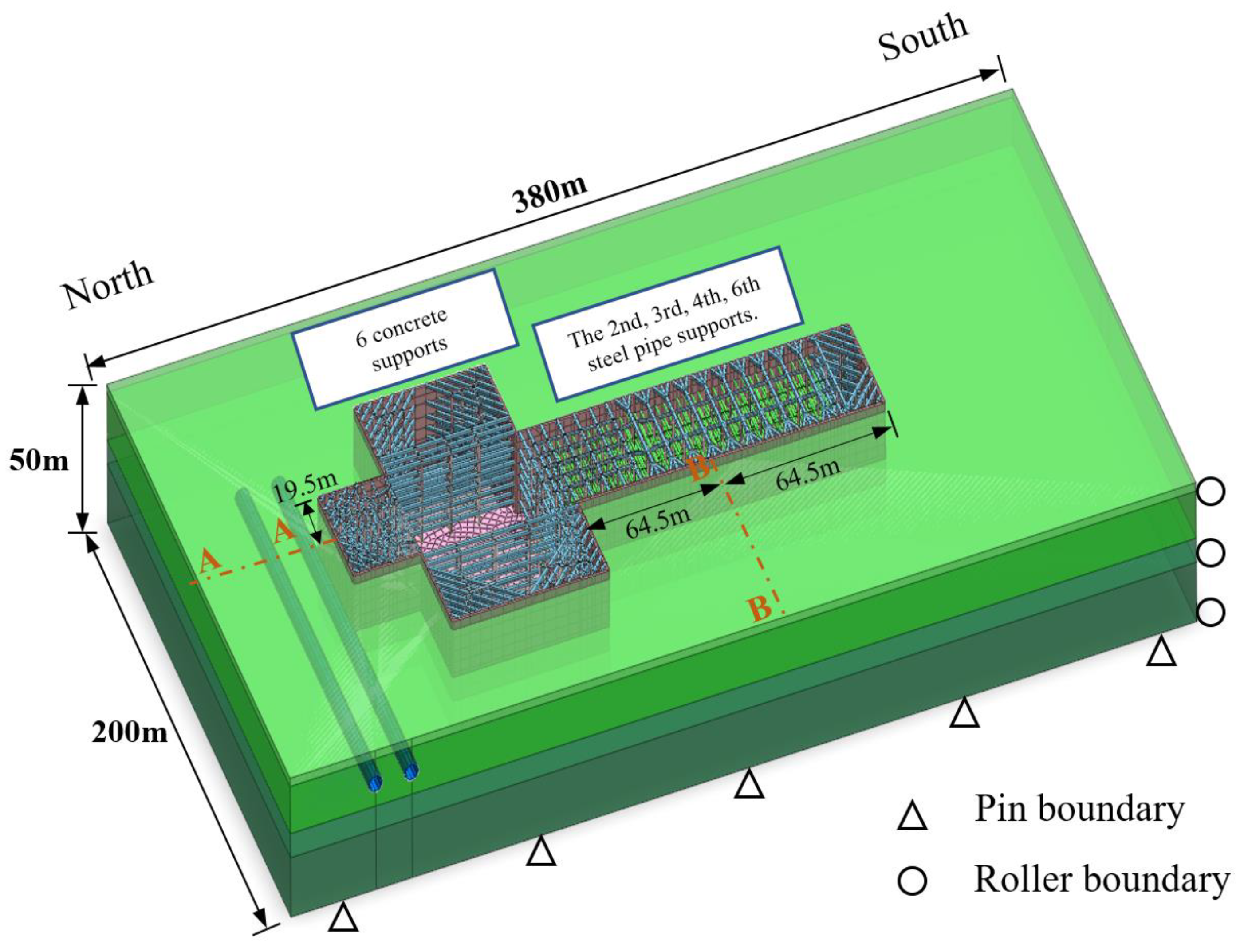
Figure 4.
Layout of support structure.

Figure 5.
Vertical displacement of tunnel vault.

Figure 6.
Horizontal displacement of tunnel haunch.

Figure 7.
Vertical displacement distribution of tunnel vault.
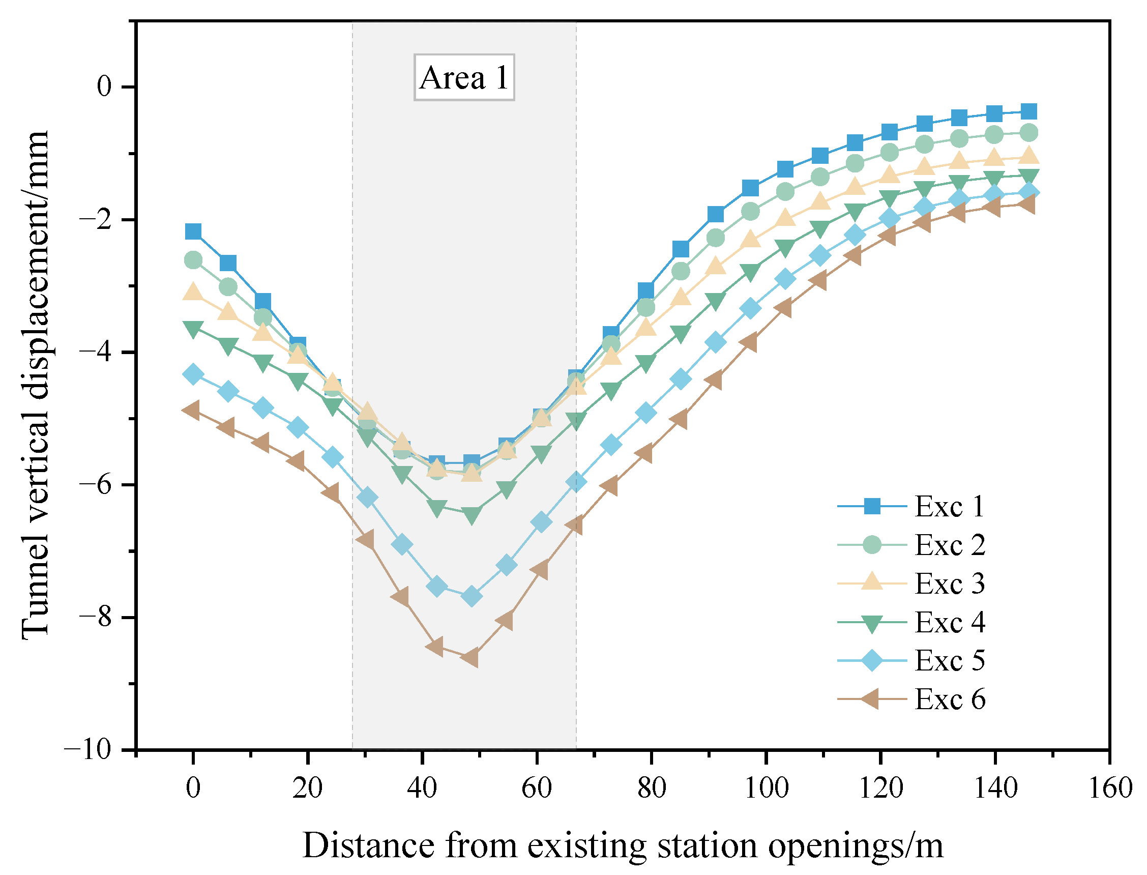
Figure 8.
Horizontal displacement distribution of tunnel vault.
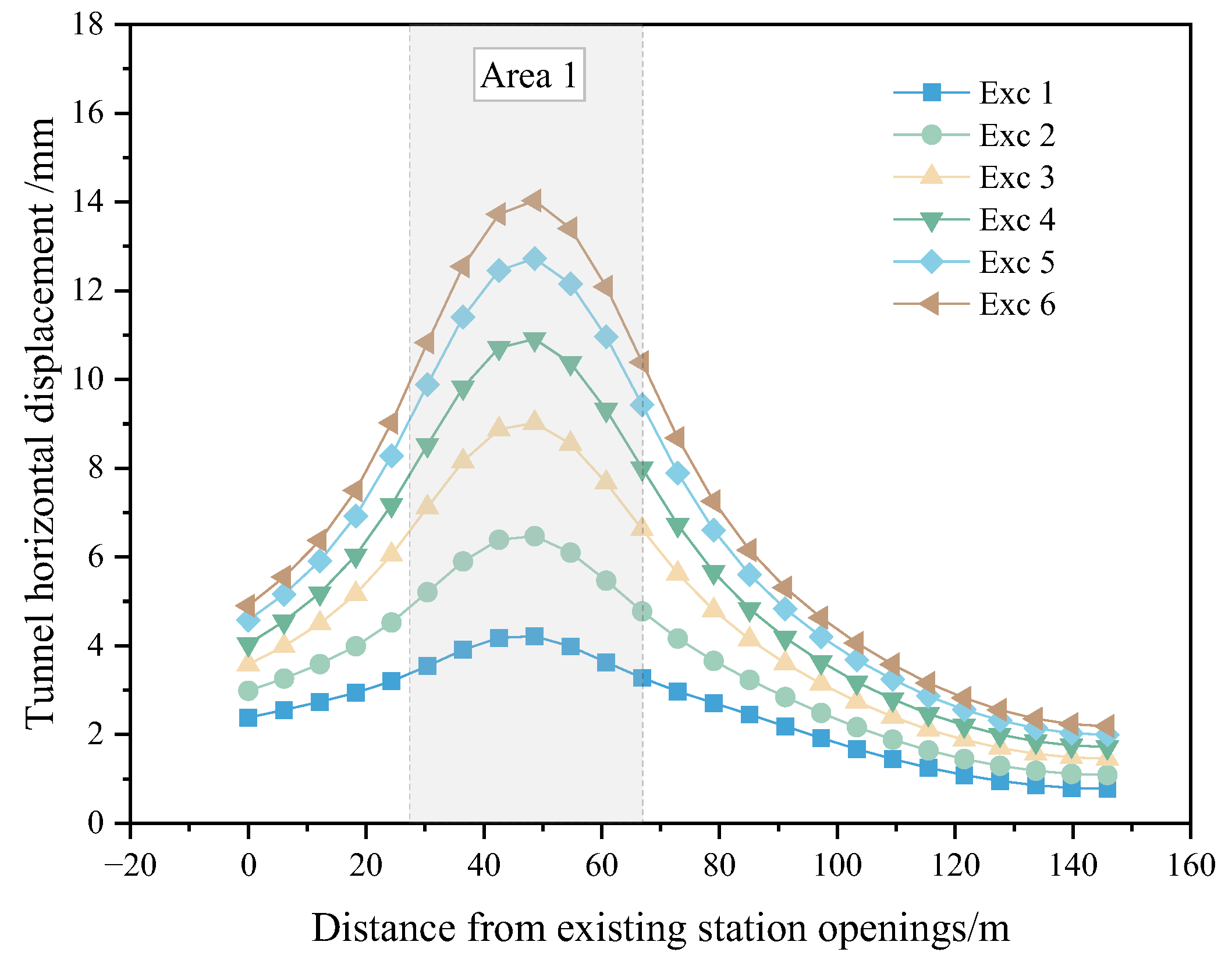
Figure 9.
Vertical displacement distribution of ground surface.

Figure 10.
Key construction steps.

Figure 11.
Time history curve of tunnel displacement (A-A section).

Figure 12.
Horizontal displacement of diaphragm wall.

Figure 13.
Tunnel deformation (×200).
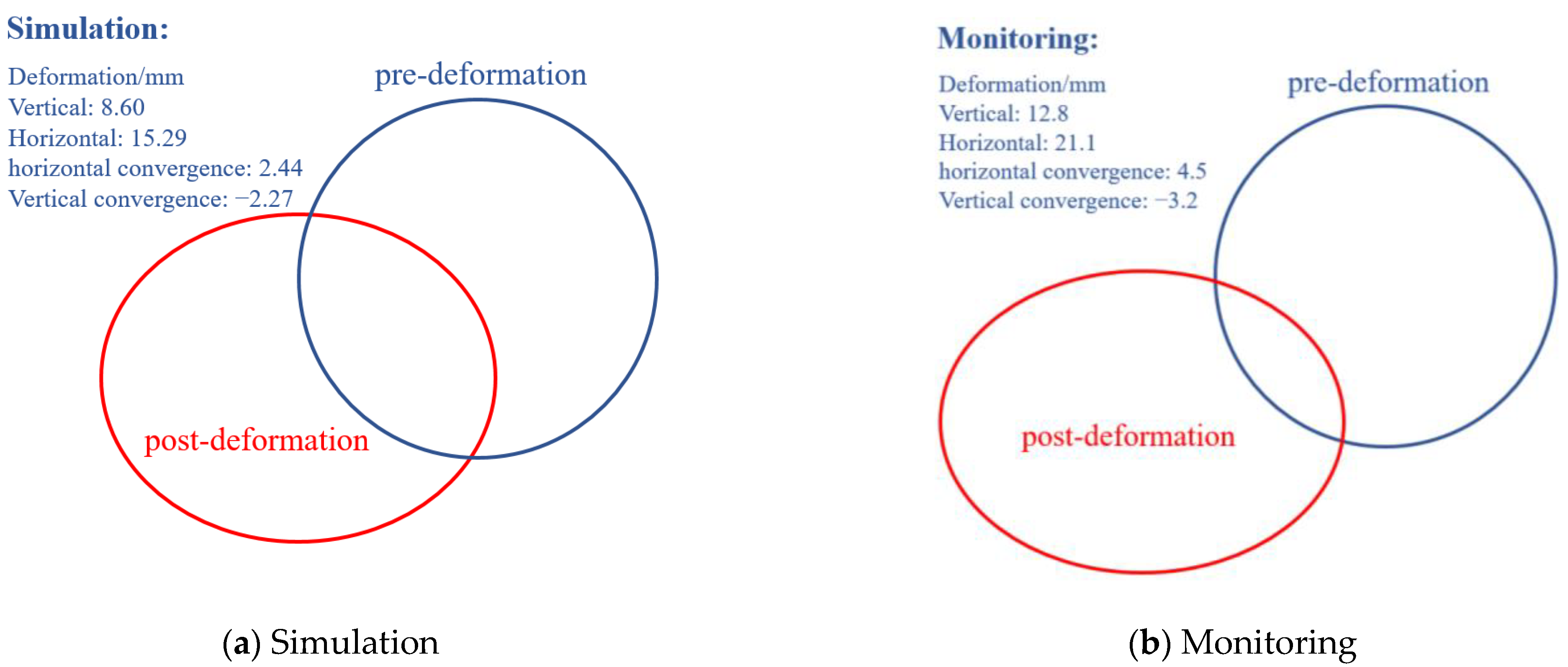
Figure 14.
Sensitivity analysis of retaining structure parameters.


Table 1.
Deformation monitoring control indicators.
| Monitoring Projects | Preliminary Alert Threshold | Alert Threshold | Control Limit |
|---|---|---|---|
| Absolute structural deformation | 6.0 mm | 8.0 mm | 10.0 mm |
Table 2.
Physical and mechanical properties of soil.
| Stratigraphic Sequence | Unit Weight (kN/m3) | Compression Modulus (MPa) | Direct Shear | |
|---|---|---|---|---|
| Friction Angle (°) | Cohesion (kPa) | |||
| Stockpile soil | 18.2 | 5 | 15.0 | 12.0 |
| Gravelly clay | 18.1 | 6 | 23.0 | 22.0 |
| Strongly weathered granite | 18.9 | 12 | 27.0 | 25.5 |
| Fully weathered granite | 18.6 | 8 | 24.0 | 24.5 |
Table 3.
Simulation model parameter description.
| Parameters | Basic Size/mm | Unit Weight (kN/m3) | Elastic Modulus (GPa) | Poisson’s Ratio | Element Type |
|---|---|---|---|---|---|
| lining | Diameter 6000 Thickness 300 | 24 | 34.5 | 0.1 | Plate |
| diaphragm wall | 1000/1200 | 24 | 31.5 | 0.2 | Plate |
| Bracing I | 600 × 600 | 24 | 31.5 | 0.2 | implantable truss |
| Bracing II | 1000 × 1200 | 24 | 31.5 | 0.2 | implantable truss |
| pipe support | Diameter 800 Thickness 20 | 76 | 250 | 0.25 | implantable truss |
| lattice column | 400 × 400 hollow | 76 | 250 | 0.25 | implantable beam |
| pile | 1200 | 24 | 31.5 | 0.2 | implantable truss |
Disclaimer/Publisher’s Note: The statements, opinions and data contained in all publications are solely those of the individual author(s) and contributor(s) and not of MDPI and/or the editor(s). MDPI and/or the editor(s) disclaim responsibility for any injury to people or property resulting from any ideas, methods, instructions or products referred to in the content. |
© 2024 by the authors. Licensee MDPI, Basel, Switzerland. This article is an open access article distributed under the terms and conditions of the Creative Commons Attribution (CC BY) license (https://creativecommons.org/licenses/by/4.0/).
Share and Cite
MDPI and ACS Style
Han, Y.; Xu, Q.; Cui, Y. Deformation of Existing Shield Tunnel Adjacent to Deep Excavations: Simulation and Monitoring Analysis. Appl. Sci. 2024, 14, 4153. https://doi.org/10.3390/app14104153
AMA Style
Han Y, Xu Q, Cui Y. Deformation of Existing Shield Tunnel Adjacent to Deep Excavations: Simulation and Monitoring Analysis. Applied Sciences. 2024; 14(10):4153. https://doi.org/10.3390/app14104153
Chicago/Turabian StyleHan, Yufeng, Qianwei Xu, and Yuebang Cui. 2024. "Deformation of Existing Shield Tunnel Adjacent to Deep Excavations: Simulation and Monitoring Analysis" Applied Sciences 14, no. 10: 4153. https://doi.org/10.3390/app14104153
Note that from the first issue of 2016, this journal uses article numbers instead of page numbers. See further details here.