


The Effect of Resin Interleafing on the Wedge Peel Strength of CF/PEEK Manufactured by Laser-Assisted In Situ Consolidation
College of Materials Science and Technology, Nanjing University of Aeronautics and Astronautics, Nanjing 210016, China
*
Author to whom correspondence should be addressed.
Coatings 2024, 14(5), 635; https://doi.org/10.3390/coatings14050635
Submission received: 21 April 2024
/
Revised: 12 May 2024
/
Accepted: 15 May 2024
/
Published: 17 May 2024
(This article belongs to the Special Issue Surface Science of Degradation and Surface Protection)
Abstract
:In this work, a novel approach involving coating fine PEEK powder on prepreg is introduced to improve wedge peel strength and reduce interlaminar voids. CF/PEEK laminates with resin interleaving are in situ consolidated by laser-assisted fiber placement. The morphology of the powdered surface is obtained using an optical profilometer, and the surface roughness and volume of added resin are calculated accordingly. Interface and surface temperature are measured during the layup process. Thermal history indicates that very short bonding time is the dominating factor for voids and limited interlayer strength. Laminate porosity and microscopic features are characterized with an optical microscope. The porosity of resin-interleaved laminates decreases to 3.7%, while the resin content only increases by 4.5% in the meantime. This is because interlayer resin particles rapidly melt under laser heating and quickly fill the voids between layers. The wedge peel strength of resin-interleaved laminates can increase by 30.1% without a repass treatment. This could be attributed to the increase in resin intimate contact and reduction in interlayer voids.
1. Introduction
The application of thermoplastic composites is gradually expanding. Their advantageous properties, including lightweight, short cycle time, and recyclability, have attracted attention in the aerospace industry [1,2,3]. Laser-assisted fiber placement (LAFP) is a promising additive technique that the thermoplastic prepreg can be consolidated in situ during the layup process. However, the performance of laminates manufactured by AFP currently lags behind those produced by traditional methods like molding and autoclaving. Minimizing this performance gap is the focus of recent studies [4,5].
The impact of processing parameters in LAFP has been thoroughly investigated, including laser power, nip-point temperature, compaction force, laying speed, mold temperature, etc. [6,7,8,9,10]. However, the lower strength is essentially attributed to interlayer voids, because the consolidation time between layers is usually less than 1 s during layup. This characteristic of LAFP cannot be altered.
According to the fusion bonding model proposed by Lee W. et al. [11,12], a low degree of resin contact leads to interlaminar voids and consequently lower bonding strength. The exposed dry fibers on the thermoplastic tape surface are obstacles between layers [13,14,15]. A direct manner to reduce such voids is by adding resin between layers. In the work of Qureshi [4], Hulcher [16], and Miao [17], resin film interleaved thermoplastic laminates manufactured by AFP have shown better properties in peel strength and interlaminar shear strength (ILSS), respectively. However, further thermal treatment like repass treatment is needed to melt the added resin film. Repass treatment means reheating and pressing the current layer by the AFP machine without laying new tape [18,19]. This process comes at the cost of production efficiency. Moreover, the resin film used usually has a thickness of 15–100 μm [17,20]. Fiber-dominated properties are weakened because of the increase in resin volume content [21].
In this work, a novel approach involving coating fine PEEK powder on prepreg is introduced to enhance wedge peel strength and reduce interlaminar voids. Unlike resin films, the added resin powder melts more rapidly during laser heating, eliminating the necessity for subsequent heat treatment. Moreover, minimal amounts of resin powder can be added, ensuring the mechanical properties of the laminate. This study investigates the surface morphology of prepreg with coated PEEK powder and explores the thermal history during layup. The feasibility of adding PEEK powder to improve the wedge peel strength is discussed.
2. Materials and Methods
2.1. Material and Equipment
A unidirectional thermoplastic prepreg Cetex TC1200 AS-4D/PEEK (TenCate Co., Ltd., Nijverdal, The Netherland)was used in this work. CF/PEEK has excellent mechanical and heat resistance properties. It has been commonly used for LAFP-related research work [6,8,9,10]. The tape is 12 inches in width when received and is slit to 6.35 mm for fiber placement. The relevant properties of the as-received tape are listed in Table 1.
Placement trials were performed using a laser ATP system designed by the authors, as depicted in Figure 1.
The laser ATP head was mounted on an industrial robot (KUKA KP2700). A 2 kW near-infrared laser source (Raycus Fiber Laser Technology Co., Wuhan, China) ensured the energy needed for the layup process. The laser power was sufficient to heat the material to its melting temperature (343 °C). A customized integrating lens caused the laser beam to focus on the nip point with spot sizes of 7 × 20 mm. A coaxial temperature sensor (Sensortherm sensor, Steinbach, Germany) was integrated into the lens to detect laser spot temperature. Due to the high energy density of the laser, the material heating rate was rapid, so the laser power was close-loop-regulated by a control system (Sensortherm M serious controller) according to its rapid PID algorithm. In this way, the nip-point temperature remained constant during the layup process.
A Fluoro rubber roller with 55 shore hardness (Yangzhong Rubber and Plastics Co., Yangzhong, China) was used to provide sufficient consolidation force at elevated temperatures. A torque motor attached to the feeding reel could adjust the tow tension to the set value. The prepreg surface temperature and interlaminar temperature during the layup process were measured with an infrared camera (FOTRIC Infrared Technology Co., Dallas, TX, USA) and a K-type thermocouple (0.1 mm in diameter), respectively.
The key parameters of the LAFP equipment are listed in Table 2.
2.2. Resin Powder Interleafing
Resin film (15–100 μm) could be added between layers to enhance interlaminar strength. However, resin-rich interleaves reduce fiber-related properties such as tensile strength, as the fiber fraction is relatively decreased. In preliminary experiments, it was observed that the resin film applied to the surface of the prepreg was not easily melted during laser heating. This was attributed to the significantly higher absorption rate of carbon fibers compared to the resin, resulting in the rapid heating of the fibers and the slower heating of the resin film. Consequently, the film hindered interlaminar bonding rather than facilitating this process. Therefore, additional thermal treatment like repass treatment is necessary for film interleafing. However, such additional thermal treatment sacrifices laydown efficiency. Using powder coating helps reduce the amount of resin added, contributing to the mechanical properties of the component. Moreover, resin particles have a large surface area, making them more prone to melting under laser irradiation without any further treatment.
Victrex 90G PEEK powder was selected due to its low viscosity. This type of resin is produced by Victrex Company (Lancashire, UK) in the UK and is commonly used in injection molding. It exhibits the ability to rapidly fill interlayer voids once melted [22,23]. It is a high-performance thermoplastic polymer, semi-crystalline, depth-filtered granules for injection molding and other processes, with very easy flow properties. Typical application areas include complex geometries with thinner cross-sections or long flow lengths. It is also suitable for aggressive environments and food contact applications. The relevant properties of the PEEK powder are listed in Table 3. The average diameter of the powder was about 20 μm when received. The small size of the particles facilitated a large specific surface area, enabling rapid melting under laser heating.
The PEEK powder was coated onto the prepreg surface using an electrostatic spraying device. As shown in Figure 2, due to electrostatic attraction, the powder can stably adhere to the film surface. The amount of added powder was controlled by the air pressure during spraying. The weight of added power is calculated according to the mass difference of the prepreg before and after powder coating. Three different coating levels, namely low, medium, and high coating amounts, were set as experimental variables, designated as P1, P2, and P3, respectively. The control group in the experiment, which consisted of prepreg without resin addition, is labeled as NP (no powder). The precise quantities of powder addition are displayed in Table 4.
2.3. Placement Trials
According to studies in the literature, higher temperatures, increased pressure, and appropriate fiber tension can yield optimal bonding strength. Based on the author’s preliminary experiments, the optimal layup process parameters were a layup speed of 100 mm/s, a fixed nip temperature of 400 degrees, a layup pressure of 100 N, and a fiber tension of 8 N. These process parameters were compatible with the layup equipment in this paper and closely align with the recommendations in the literature [6,9,10,24].
A schematic diagram of laser-assisted forming with PEEK powder coating is shown in Figure 3a. A thermal insulation board was placed on the mold to prevent heat loss and promote interlayer bonding. The first prepreg layer was double-sided-taped onto a thermal insulation board, followed by subsequent layers being sequentially laid up to form a [0]4 laminate. To facilitate peel testing, a small piece of aluminum foil was placed between the second and third layers as a pre-cut crack. Ultimately, an interleaved laminate with a size of 6.35 × 300 mm was produced, as depicted in Figure 3b.
Multiple specimens were prepared for each set of experimental parameters. Among these, five were used for peel testing, while one was used for cross-sectional profiles. After trimming the edges of the specimens, their widths were measured using a vernier caliper, with the specimen width maintained at 6.35 mm.
2.4. Interlaminar Strength Characterization
The quality of the interlaminar bond is essential to product quality. Composite interlaminar properties are usually evaluated by short beam strength (SBS, ASTM D2344 [25]) and double-cantilever beam (DCB, ASTM D5528 [26]) tests. Both are sensitive to resin properties and are often utilized for benchmarking. However, plastic deformation in thermoplastic laminates during SBS testing may lead to complex failure modes and inaccurate interlaminar strength [6]. This is thought to be due to the voids and poor fiber–resin bonding in laminates.
The wedge peel test has been employed to evaluate the interlaminar properties of samples made by the AFP process [24,27]. The wedge peel test requires a specimen only 4–6 layers thick, while the DCB test requires the thickness to be between 3 and 5 mm, which means 24 to 40 layers, so the specimen preparation and testing of the peel test is more time-saving. The wedge peel test shares similar failure modes with the DCB test and shows a high correlation with test results. Peaks in both the wedge peel strength and DCB fracture toughness data are observed to occur well [28]. These favorable factors make it a commonly used quality indicator in AFP studies.
The wedge peel test equipment used in this study is illustrated in Figure 4. It has a clamp attached to a universal testing machine and a peeling blade separating the specimen. The peeling blade has a thickness of 3.2 mm and an angle of 30 degrees. The peel force was measured using a 200 N force sensor, while peel displacement was obtained through position sensors in the universal testing machine, both sampled at a frequency of 50 Hz. During the peel test, significant variability in peel force was observed at the initial and final peel ends of the specimen, and these data were discarded. Data from the relatively stable peel region in the middle of the specimen were selected for statistical analysis.
A SENSOFAR-SNEOX 3D optical profiler (Sensofar, Barcelona, Spain)was used to evaluate surface morphology so that the as-received tape surface and the coated surface morphology were compared. Furthermore, according to surface profile data, the average thickness of interleaved powder resin was calculated. The precise quantities of powder addition are displayed in Table 4. An integrated SNEOX 3D optical microscope (Sensofar, Barcelona, Spain)was used for the micrographs of the material surface and for observing the resin particle size.
Samples made by laser-assisted consolidation were ground and polished, and the polished surfaces of cross-sections were observed with an optical microscope to analyze the characteristics of voids and fiber–resin distribution. The optical microscope used for cross-section observation was Leica DVM5000 (Heidelberg, Germany). Porosity was calculated according to micrographs, with the help of ImageJ software v1.53.
PEEK resin within the raw material undergoes fusion with the added PEEK powder during laser consolidation. To discern the interface between these constituents, a polarizing filter with a yellow color was attached to the optical microscope. Due to the optical differences between the two resins, the interface between them can be distinguished. This allows for the study of the flow behavior of PEEK powder during the forming process.
3. Results and Discussion
3.1. Surface Micrographs
For the experiment, different resin coating amounts were set as experimental variables, labeled P1, P2, P3, and NP (no resin added). Their 3D surface morphology images are shown in Figure 5. Figure 5a depicts the surface without coating, and it can be seen that the surface consists of many exposed fibers, while resin-covered areas are only 12.7%. Although the raw material contains 34% resin, these resins are concentrated within the material rather than on its surface. Therefore, the exposed fibers on the surface become obstacles to the molding process. It is these areas of exposed fibers that cause interlayer voids and lower interlayer strength. Figure 5b–d correspond to different levels of PEEK powder coating, with resin particle sizes approximately 20 μm. It can be observed that with the increase in PEEK powder coating amount, the size of exposed fibers decreases continuously, and the average thickness of resin on the prepreg surface increases.
Based on the surface morphology data, the average resin thickness and the proportion of resin-covered area on the surface of the prepreg under different coating amounts were calculated, as demonstrated in Table 4. This suggests that as the PEEK powder content increases, the proportion of exposed fibers on the prepreg surface decreases. Powder coating has a relatively minor impact on laminate resin fraction. The average thickness of the resin interleaf of samples P1 and P2 are only 6.1 and 9.3 μm, significantly thinner than the resin films reported in the literature. According to the measurement, the average resin thickness of P3 samples is 16.6 μm, which is close to the resin film thickness reported in the literature. This powdered interleaf has a relatively minor impact on the fiber content of the laminate while maintaining fiber-related mechanical properties, such as tensile strength.
According to the fusion bonding model, close contact between interlayer resins is essential for interlayer bonding. However, this process is impeded by exposed fibers in the LAFP process. In regions with abundant fibers on the prepreg surface, the resin must be squeezed into the interlayer from the interior of the prepreg. Achieving this squeezed resin flow is challenging for LAFP due to the resistance of fiber and the very limited process time. Powder coating dramatically increases the resin content on the surface of the prepreg, rising from 12.7% (as-received prepreg) to 81.2% in the P3 sample. Therefore, adding interlayer powder helps improve the intimate contact of the prepreg and enhances the interlayer bonding strength.
3.2. Thermal History
In order to analyze the thermal history during the forming process, an infrared thermal imager and K-type thermocouples were used to measure the surface temperature of the prepreg and the interlayer temperature, respectively. The measurement results indicate that interlayer powder coating has no significant impact on the thermal history during processing. This thermal history test was conducted using a 1080 nm laser source (provided by LASERLINE Company Munich, Germany), and very similar results were achieved. This phenomenon can be attributed to two reasons. Firstly, the surface temperature of the prepreg was controlled in a closed-loop manner using the layup equipment, and the irradiation point temperature remained stable at the set value of 400 °C. Secondly, the amount of added powder particles was minimal, which had little effect on the thermal properties of the laminate.
The surface temperature of the P1 sample measured with the infrared thermal imager is shown in Figure 6a. Surface temperature data for the first, second, third, and fourth layers were recorded. The temperature rapidly increases with laser irradiation, and the heating rate and peak temperature are regulated with the laser heating controller. Since the processing parameters for each layer are exactly the same, the thermal histories are almost identical. Figure 6 also shows that the temperature before and after roller contact is 370 °C and 290 °C, respectively. This indicates that the resin remains in a molten state for approximately 1 s.
Figure 6b shows the temperature at a spot between the first and second layers during the process obtained with a K-type thermocouple. As shown in Figure 6b, the thermal couple was attached to the first layer. When laying the second layer, the spot temperature matches the set temperature at 400 °C, higher than the Tm of PEEK(343 °C). When laying the third and fourth layers, laser heat conduction occurred downwards, causing the peak temperature at the spot to reach 315 °C and 230 °C, respectively. The transferred heat increased the local temperature above the resin’s Tg point (251 °C).
Although the interlayer bonding time for in situ consolidation was very short, when laying subsequent layers, heat and pressure conduction occurred downwards, causing the substrate prepreg to undergo extra heating and compaction. The interlayer resin of the substrate prepreg cannot melt during this process, nor can it fill the interlayer voids. However, the additional heat and pressure facilitate the segment movement of the resin [29], which positively affects the interlayer bonding strength.
3.3. Wedge Peel Strength
The wedge peel strength of all samples was tested to assess the effect of coated powder on interlayer strength. The test results are shown in Figure 7. The unstable peeling force was induced at the beginning and end of a sample. This may be attributed to the change in the speed of the universal test machine and interlayer defects. Unstable data were excluded from the analysis, and the average wedge peel force of each group of samples was calculated accordingly.
The wedge peel strengths of the samples were calculated as S = F/w, where S, F, and w mean the wedge peel strength, wedge peel force, and sample width, respectively. To make the results more reliable, the width of every sample was measured and trimmed to 6.35 mm. Therefore, the defects on the edges of the samples did not affect the experimental results. The wedge peel strength of each experimental group is shown in Figure 8.
As shown in Figure 8, when the prepreg surface is uncoated, the peel strength is 2.6 N/mm. As the powder coating amount increases, the peel strength increases, reaching 3.4 ± 0.3 N/mm and 3.2 ± 0.4 N/mm, respectively. This indicates that a small amount of resin powder can melt at a laying speed of 100 mm/s, and the melted resin quickly flows to fill the interlayer voids, resulting in tighter interlayer bonding. However, when the average thickness of the coated powder increases to 21.6 g/m2, the peel strength decreases. Due to the significant difference in laser absorption between resin particles and carbon fibers, carbon fibers primarily absorb the radiation heat of the laser beam. The heat is then transferred to the surrounding resin through thermal conduction. When the powder coating is too much, or the resin layer thickness is too thick, the energy transferred by thermal conduction is insufficient to melt all the coated resin. The unmelted resin particles instead greatly hinder interlayer bonding, resulting in lower peel strength and larger scatter values.
3.4. Porosity and Microstructure
The microscopic cross-sectional images of the specimens prepared under different experimental conditions are shown in Figure 9. And the effect of the weight of coated powder on porosity in shown in Figure 10.
Figure 9a depicts a specimen without surface powder coating, where noticeable voids are present. The porosity content of the sample is 7.2% as shown in Figure 10. Figure 9b,c show micrographs of specimens with 7.9 g/m2 and 12.2 g/m2 coated PEEK powder, and sample porosity is 3.4% and 2.1% respectively. In Figure 9b, regions with higher resin content can be observed. Despite the lower resin addition, there are still voids between the layers, but the dispersion of fibers and resin becomes relatively more uniform. This indicates that the added resin melts and flows during the layup process, which fills the interlayer voids under compaction force. At this point, the interlayer wedge peel strength is also the highest, reaching 3.3 N/mm. As shown in Figure 9c, as the amount of added powder increases to 12.2 g/m2, a clear resin-rich area appears between the layers.. If the resin coating amount continues to increase and reaches 21.6 g/m2, as shown in Figure 9d, voids begin to appear again in the interlayer resin region. According to Figure 10, sample porosity rises to 8.0%. This indicates that the resin is not fully melted at this point and that resin particles impede interlayer bonding.
Upon zooming in on Figure 9b, it can be observed that the coated resin particles not only fill the interlayer voids after melting but also infiltrate along the voids toward the thickness direction of the prepreg. This is because the resin inside the prepreg experiences the hindrance effect of fibers, resulting in weaker flowability in the thickness direction, making it difficult to fill the interlayer voids [13]. However, the resin coated between layers exhibits strong fluidity, filling the interlayer voids and infiltrating “backward” into the prepreg. The added resin powder effectively reduced the porosity of the laminate.
If the powder coating is excessive, for example, exceeding 20 g/m2, it becomes difficult to melt during the laying process. This results in longer defect areas along the interface. In Figure 9d, aggregated resin was found in the microscopic image of the specimen parallel to the fiber direction. Although the resin is heated and deformed into an oval shape, it does not fully melt. As a result, the surrounding fibers form “eye-shaped” defect areas. This discovery suggests that for resin interlayers thicker than 30 μm, achieving in situ consolidation by LAFP becomes impracticable.
The schematic diagram of interlayer void formation and the void filling of coated resin during layup are shown in Figure 11. There are some dry fibers and fiber-rich areas on the tape surface as depicted in Figure 11a. Laser heating cannot increase the resin content on the surface; instead, it tends to soften and roughen the surface. Due to the short processing time of high temperature and consolidation force, it is not possible to let resin flow completely [8], which causes many interlaminar voids and dry fibers, as depicted in Figure 11a. The added resin particles can rapidly melt during laser heating, flow under pressure, and fill the interlayer voids. This mechanism elucidates how powder coating can reduce the interlayer porosity and enhance peel strength, as depicted in Figure 11b. However, if excessive PEEK powder is added between the layers, it may not fully melt during the consolidation process. The unmelted PEEK particles are heated and compressed by compaction force, forming an “eye-shaped” defect area. This is shown in Figure 11c.
4. Conclusions
In this study, a novel approach involving the coating of fine PEEK powder on prepreg was introduced to enhance wedge peel strength and reduce interlaminar voids in CF/PEEK laminates consolidated in situ by laser-assisted fiber placement. Morphological analysis revealed a decrease in dry fiber and more uniform fiber–resin distribution. The thermal history during layup indicated a short bonding time as a dominant factor influencing void formation and limited interlayer strength. Furthermore, wedge peel strength significantly increased with the addition of a small quantity of resin, attributed to improved resin contact and reduced interlayer voids.
The successful implementation of this novel approach highlights its potential for improving the mechanical properties of thermoplastic composites manufactured by laser-assisted fiber placement. By optimizing resin powder coating levels, it is possible to achieve enhanced interlayer bonding strength while maintaining fiber-related mechanical properties. Future research could explore the applicability of this method across various thermoplastic composite systems and processing conditions, further advancing the field of additive manufacturing in aerospace.
Author Contributions
Conceptualization, methodology, and writing—original draft preparation, R.W.; validation, R.W. and E.X.; resources, R.W. and L.W.; project administration, L.W. All authors have read and agreed to the published version of the manuscript.
Funding
This research received no external funding.
Institutional Review Board Statement
Not applicable.
Informed Consent Statement
Not applicable.
Data Availability Statement
The data presented in this study are available upon request from the corresponding author.
Conflicts of Interest
The authors declare no conflicts of interest.
References
- Mills, A. Automation of carbon fibre preform manufacture for affordable aerospace applications. Compos. Part A Appl. Sci. Manuf. 2001, 32, 955–962. [Google Scholar] [CrossRef]
- Bandaru, A.K.; Clancy, G.; Peeters, D.; O’Higgins, R.M.; Weaver, P.M. Properties of a thermoplastic composite skin-stiffener interface in a stiffened structure manufactured by laser-assisted tape placement with in situ consolidation. Compos. Struct. 2019, 214, 123–131. [Google Scholar] [CrossRef]
- Penumakala, P.K.; Santo, J.; Thomas, A. A critical review on the fused deposition modeling of thermoplastic polymer composites. Compos. Part B Eng. 2020, 201, 108336. [Google Scholar] [CrossRef]
- Qureshi, Z.; Swait, T.; Scaife, R.; El-Dessouky, H.M. In situ consolidation of thermoplastic prepreg tape using automated tape placement technology: Potential and possibilities. Compos. Part B Eng. 2014, 66, 255–267. [Google Scholar] [CrossRef]
- Comer, A.J.; Ray, D.; Obande, W.O.; Jones, D.; Lyons, J.; Rosca, I.; O’ Higgins, R.M.; McCarthy, M.A. Mechanical characterisation of carbon fibre–PEEK manufactured by laser-assisted automated-tape-placement and autoclave. Compos. Part A Appl. Sci. Manuf. 2015, 69, 10–20. [Google Scholar] [CrossRef]
- Stokes-Griffin, C.M.; Compston, P. The effect of processing temperature and placement rate on the short beam strength of carbon fibre–PEEK manufactured using a laser tape placement process. Compos. Part A Appl. Sci. Manuf. 2015, 78, 274–283. [Google Scholar] [CrossRef]
- Chen, J.; Fu, K.; Li, Y. Understanding processing parameter effects for carbon fibre reinforced thermoplastic composites manufactured by laser-assisted automated fibre placement (AFP). Compos. Part A Appl. Sci. Manuf. 2021, 140, 106160. [Google Scholar] [CrossRef]
- Liu, H.; Li, Y.; Huan, D.; Wang, W.; Li, Y.; Li, L. Influence of Curvature Feature on Laser Heating during Tape Placement Process for Carbon Fiber Reinforced Polyether Ether Ketone Composite. Polymers 2023, 15, 289. [Google Scholar] [CrossRef]
- Song, Q.; Liu, W.; Chen, J.; Zhao, D.; Yi, C.; Liu, R.; Geng, Y.; Yang, Y.; Zheng, Y.; Yuan, Y. Research on void dynamics during in situ consolidation of CF/high-performance thermoplastic composite. Polymers 2022, 14, 1401. [Google Scholar] [CrossRef]
- Miao, Q.; Dai, Z.; Ma, G.; Niu, F.; Wu, D. Effect of consolidation force on interlaminar shear strength of CF/PEEK laminates manufactured by laser-assisted forming. Compos. Struct. 2021, 266, 113779. [Google Scholar] [CrossRef]
- Lee, W.I.; Springer, G.S. A model of the manufacturing process of thermoplastic matrix composites. J. Compos. Mater. 1987, 21, 1017–1055. [Google Scholar] [CrossRef]
- Kim, Y.H.; Wool, R.P. A theory of healing at a polymer-polymer interface. Macromolecules 1983, 16, 1115–1120. [Google Scholar] [CrossRef]
- Çelik, O.; Peeters, D.; Dransfeld, C.; Teuwen, J. Intimate contact development during laser assisted fiber placement: Microstructure and effect of process parameters. Compos. Part A Appl. Sci. Manuf. 2020, 134, 105888. [Google Scholar] [CrossRef]
- Çelik, O.; Choudhary, A.; Peeters, D.; Teuwen, J.; Dransfeld, C. Deconsolidation of thermoplastic prepreg tapes during rapid laser heating. Compos. Part A Appl. Sci. Manuf. 2021, 149, 106575. [Google Scholar] [CrossRef]
- Slange, T.K.; Warnet, L.L.; Grouve, W.J.B.; Akkerman, R. Deconsolidation of C/PEEK blanks: On the role of prepreg, blank manufacturing method and conditioning. Compos. Part A Appl. Sci. Manuf. 2018, 113, 189–199. [Google Scholar] [CrossRef]
- Hulcher, A.B.; Banks, W.I., III; Pipes, R.B.; Tiwari, S.N.; Cano, R.J.; Johnston, N.J. Automated fiber placement of PEEK/IM7 composites with film interleaf layers. In Proceedings of the 46th International SAMPE Symposium and Exhibition, Covina, CA, USA, 6–10 May 2001; pp. 1998–2012. [Google Scholar]
- Miao, Q.; Dai, Z.; Ma, G.; Niu, F.; Wu, D. CF/PEEK interleaved laminates with PEEK film interleaving manufactured by laser-assisted forming: Microstructure and interlaminar shear strength. Compos. Part A Appl. Sci. Manuf. 2023, 172, 107592. [Google Scholar] [CrossRef]
- Wang, X.; Chen, C.; Hu, S.; Chen, Z.; Jiang, W.; Shen, G.; Huang, Z.; Zhou, H. In-situ infrared annealing for laser-assisted automated fiber placement to enhance interlaminar properties without sacrificing laydown efficiency. Compos. Part A Appl. Sci. Manuf. 2024, 183, 108214. [Google Scholar] [CrossRef]
- Chanteli, A.; Bandaru, A.K.; Peeters, D.; O’Higgins, R.M.; Weaver, P.M. Influence of repass treatment on carbon fibre-reinforced PEEK composites manufactured using laser-assisted automatic tape placement. Compos. Struct. 2020, 248, 112539. [Google Scholar] [CrossRef]
- Kim, J.W.; Lee, J.S. Influence of interleaved films on the mechanical properties of carbon fiber fabric/polypropylene thermoplastic composites. Materials 2016, 9, 344. [Google Scholar] [CrossRef]
- de Souza, G.; Tarpani, J.R. Interleaving CFRP and GFRP with a thermoplastic ionomer: The effect on bending properties. Appl. Compos. Mater. 2021, 28, 559–572. [Google Scholar] [CrossRef]
- Ourahmoune, R.; Salvia, M.; Mathia, T.G.; Mesrati, N. Surface morphology and wettability of sandblasted PEEK and its composites. Scanning J. Scanning Microsc. 2014, 36, 64–75. [Google Scholar] [CrossRef] [PubMed]
- Abbasnezhad, N.; Khavandi, A.; Fitoussi, J.; Arabi, H.; Shirinbayan, M.; Tcharkhtchi, A. Influence of loading conditions on the overall mechanical behavior of polyether-ether-ketone (PEEK). Int. J. Fatigue 2018, 109, 83–92. [Google Scholar] [CrossRef]
- Zhang, C.; Duan, Y.; Xiao, H.; Wang, B.; Ming, Y.; Zhu, Y.; Zhang, F. The effects of processing parameters on the wedge peel strength of CF/PEEK laminates manufactured using a laser tape placement process. Int. J. Adv. Manuf. Technol. 2022, 120, 7251–7262. [Google Scholar] [CrossRef]
- ASTM D2344; Standard Test Method for Short-Beam Strength of Polymer Matrix Composite Materials and Their Laminates. ASTM: West Conshohocken, PA, USA, 2016.
- ASTM D5528; Standard Test Method for Mode I Interlaminar Fracture Toughness of Unidirectional Fiber-Reinforced Polymer Matrix Composites. ASTM: West Conshohocken, PA, USA, 2013.
- Stokes-Griffin, C.M.; Kollmannsberger, A.; Compston, P.; Drechsler, K. The effect of processing temperature on wedge peel strength of CF/PA 6 laminates manufactured in a laser tape placement process. Compos. Part A Appl. Sci. Manuf. 2019, 121, 84–91. [Google Scholar] [CrossRef]
- Johnston, N.J.; Belvin, H.L.; Cano, R.J.; Marchello, J.M.; Hulcher, A.B. A prototype research laboratory for automated fabrication of high performance composites. In Proceedings of the 12th International Conference on Composite Materials ICCM12, Paris, France, 5–9 July 1999. [Google Scholar]
- Stokes-Griffin, C.M.; Compston, P. Investigation of sub-melt temperature bonding of carbon-fibre/PEEK in an automated laser tape placement process. Compos. Part A Appl. Sci. Manuf. 2016, 84, 17–25. [Google Scholar] [CrossRef]
Figure 1.
Laser AFP equipment used in this study.

Figure 2.
Schematic diagram of prepreg slit and powder spray.

Figure 3.
Schematic diagram of laser-assisted forming with PEEK powder coating (a) and manufactured samples (b).
Figure 3.
Schematic diagram of laser-assisted forming with PEEK powder coating (a) and manufactured samples (b).

Figure 4.
Image of wedge peel test device.2.5. Other Characterization Tests.

Figure 5.
The 3D surface morphology images of the sample: (a) NP, (b) P1, (c) P2, and (d) P3.
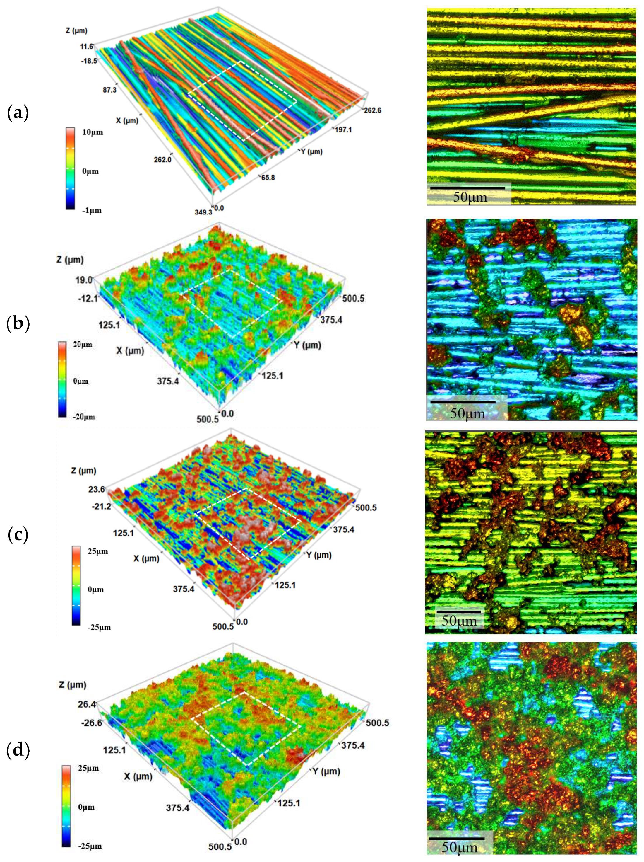
Figure 6.
Thermal history of prepreg during layup. surface temperature (a); interface temperature (b).
Figure 6.
Thermal history of prepreg during layup. surface temperature (a); interface temperature (b).

Figure 7.
Force–displacement graphs for wedge peel test: NP (a), P1 (b), P2 (c), and P3 (d).

Figure 8.
The effect of the weight of coated powder on wedge peel strength and resin mass fraction.
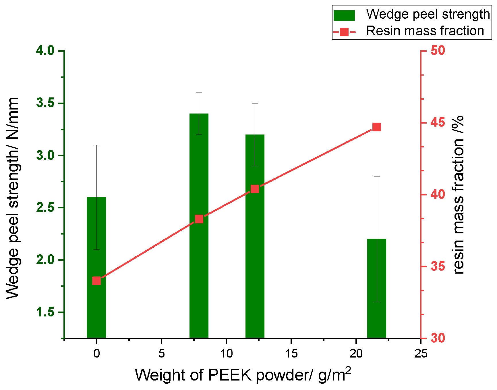
Figure 9.
Microstructure of interleaved laminates: (a) NP, (b) P1, (c) P2, and (d) P3. White ellipses indicate voids and green rectangles indicate resin-rich areas.
Figure 9.
Microstructure of interleaved laminates: (a) NP, (b) P1, (c) P2, and (d) P3. White ellipses indicate voids and green rectangles indicate resin-rich areas.
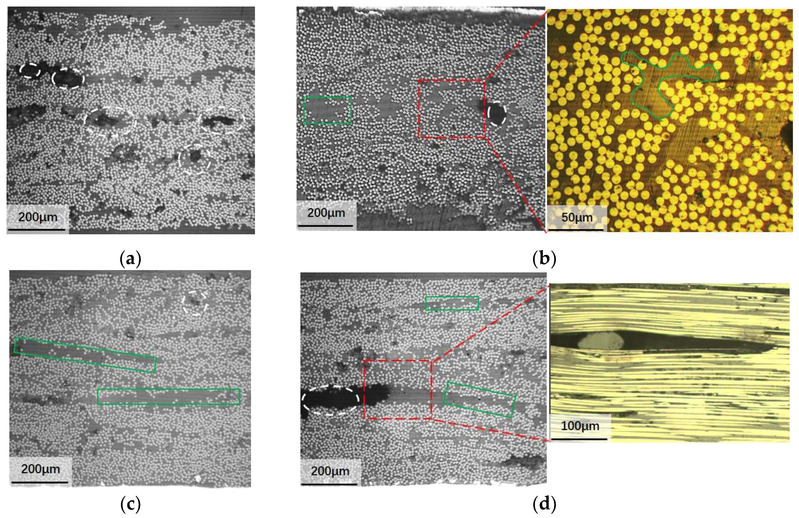
Figure 10.
The effect of the weight of coated powder on porosity and resin mass fraction.

Figure 11.
Schematic diagram of resin/fiber distribution: (a) during the LAFP process; (b) with coated PEEK powder; (c) excessive PEEK powder.
Figure 11.
Schematic diagram of resin/fiber distribution: (a) during the LAFP process; (b) with coated PEEK powder; (c) excessive PEEK powder.


Table 1.
Properties of the as-received AS4D/PEEK tape.
| Area Density/g/m2 | Resin Mass Content/% | Thickness/mm | Glass Transformation Temperature/°C | Melting Temperature/°C | Void Content/% |
|---|---|---|---|---|---|
| 223 | 34 | 0.143 | 143 | 343 | 0.7 |
Table 2.
Key parameters of the LAFP equipment.
| Part Name | Part Parameter |
|---|---|
| Roller diameter | 34 mm |
| Compaction force | 10–150 N |
| Layup speed | 10–200 mm/s |
| Laser wavelength | 1064 nm |
| Laser irradiation area | 7 × 20 mm |
| Lens focal length | 400 mm |
Table 3.
Relevant properties of the PEEK powder.
| Material Data | Conditions | Typical Value |
|---|---|---|
| Melting temperature/°C | 343 | |
| Glass transition (Tg)/°C | 143 | |
| Thermal conductivity/Wm−1K−1 | At 23 °C | 0.29 |
| Density g/cm3 | Crystalline | 1.30 |
| Density g/cm3 | Amorphous | 1.27 |
| Melt viscosity/pa·s | at 400 °C | 90 |
| Tensile strength/MPa | 110 | |
| Tensile Modulus/GPa | 3.9 |
Table 4.
The amount of resin powder coated on prepreg.
| Samples | Powder Layer Thickness in Average (μm) | Powder Weight (g/m2) | Resin Mass Fraction (%) | Surface Area Covered by Resin (%) |
|---|---|---|---|---|
| NP | 0 | 0 | 34 | 12.7 |
| P1 | 6.1 | 7.9 | 38.5 | 25.5 |
| P2 | 9.3 | 12.2 | 40.4 | 50.6 |
| P3 | 16.6 | 21.6 | 44.7 | 81.2 |
Disclaimer/Publisher’s Note: The statements, opinions and data contained in all publications are solely those of the individual author(s) and contributor(s) and not of MDPI and/or the editor(s). MDPI and/or the editor(s) disclaim responsibility for any injury to people or property resulting from any ideas, methods, instructions or products referred to in the content. |
© 2024 by the authors. Licensee MDPI, Basel, Switzerland. This article is an open access article distributed under the terms and conditions of the Creative Commons Attribution (CC BY) license (https://creativecommons.org/licenses/by/4.0/).
Share and Cite
MDPI and ACS Style
Wang, R.; Xu, E.; Wen, L. The Effect of Resin Interleafing on the Wedge Peel Strength of CF/PEEK Manufactured by Laser-Assisted In Situ Consolidation. Coatings 2024, 14, 635. https://doi.org/10.3390/coatings14050635
AMA Style
Wang R, Xu E, Wen L. The Effect of Resin Interleafing on the Wedge Peel Strength of CF/PEEK Manufactured by Laser-Assisted In Situ Consolidation. Coatings. 2024; 14(5):635. https://doi.org/10.3390/coatings14050635
Chicago/Turabian StyleWang, Ruozhou, Entao Xu, and Liwei Wen. 2024. "The Effect of Resin Interleafing on the Wedge Peel Strength of CF/PEEK Manufactured by Laser-Assisted In Situ Consolidation" Coatings 14, no. 5: 635. https://doi.org/10.3390/coatings14050635
Note that from the first issue of 2016, this journal uses article numbers instead of page numbers. See further details here.