

A Study of a Cornering Braking Control System for a Motorcycle

1
Department of Vehicle Engineering, National Taipei University of Technology, Taipei 10608, Taiwan
2
School of Information and Mechatronics Engineering, Ningde Normal University, Ningde 352100, China
*
Author to whom correspondence should be addressed.
Appl. Sci. 2022, 12(24), 12575; https://doi.org/10.3390/app122412575
Submission received: 13 November 2022
/
Revised: 27 November 2022
/
Accepted: 6 December 2022
/
Published: 8 December 2022
(This article belongs to the Topic Vehicle Dynamics and Control)
Abstract
:Featured Application
The proposed control system can effectively maintain motorcycle stability during cornering braking, which contributes to enhancing the safety of motorcycles and other single-track vehicles.
Abstract
Motorcycles are widely used in people’s daily lives for their convenience. Due to their characteristic of static instability, they have a larger roll angle than cars when turning, which brings the hidden danger of overturning. When a motorcycle is turning and braking simultaneously, the overturn risk rises dramatically. This study presents a novel control system that can ensure stability and braking performance during turning and braking. Given the direct impact of tires on a motorcycle’s behavior, a motorcycle tire model was created via Magic Formula to determine the kinematic parameters that have correlated effects on the longitudinal and lateral characteristics of tires. The slip ratio was defined as the manipulated variable, and a constrained optimization model that aimed to maximize the braking performance and took the stability as the constraint condition was created and solved through the gold section method. The obtained optimal slip ratio was then used as the input for the proposed cornering braking control system that adopted the Fuzzy PID algorithm. Finally, the feasibility of the proposed controller was tested via a co-simulation method, and the simulation results were compared with an ordinary anti-lock braking system. The results demonstrate that the proposed cornering braking control system can take both motorcycle stability and braking performance into consideration at the same time, effectively increasing the security of a motorcycle during braking in a turn.
1. Introduction
It is well known that motorcycles are still popular in more and more crowded cities due to their flexibility and practicability. A general motorcycle can travel at speeds of up to 80–100 km/h, but it occupies half the space of a car, allowing them to avoid traffic jams and parking difficulties. However, the dynamics of a motorcycle are similar to an inverted pendulum system, and they have static instability. When a motorcycle is cornering, the roll angle appears to offset the centrifugal effect. If a motorcycle is cornering and braking concurrently, the risk of overturn increases greatly. With the progress of intelligent control systems in recent years, active safety systems, such as the electronic stability program (ESC), vehicle stability control (VSC) have been widely used in cars, which also provide a good reference point for improving the safety of motorcycles. Overall, given the wide application and inherent instability of motorcycles, researching and developing active safety systems for motorcycles to improve their security has great significance [1].
Previous research mainly focused on the dynamics model and stability control of motorcycles. Regarding the dynamics model, Sharp and Vittore Cossalter conducted a systematic and comprehensive study. Sharp et al. [2] primarily simplified a two-wheeler as two rigid bodies that are connected by a revolute pair and derived the dynamic equations using the Lagrange method to determine characteristics such as wobble, weave, and capsizing. In [3,4], Sharp et al. used a parametric modeling tool, Autosim, to create a nonlinear model of a motorcycle to determine its stability under braking and acceleration. Vittore Cossalter [5,6] proposed an 11-DOF nonlinear dynamic model using a Cartesian method and analyzed the kinematics, tires, steady turning, vibration, and handling characteristics of a motorcycle systematically. In [7], Cossalter et al. linearized the dynamic model from [5] and then analyzed the eigenvalue and model characteristics. In [8], by combining suspension stiffness, Cossalter et al. conducted time-domain simulation, nonlinear steady-state analysis, linear stability analysis, and frequency domain analysis. Andrea Bonci et al. [9] conducted a comparative analysis of the linear roll dynamics and nonlinear roll dynamics models of motorcycles under turning conditions. Costa L et al. [10] developed a multibody model of a Honda VFR that consisted of six bodies and eleven degrees of freedom. Vincenzo Maria Arricale et al. [11] derived a mathematical model of a motorcycle using the Lagrange method, which was a non-linear second-order ordinary differential equation (ODE). Jalti, F. et al. [12] presented longitudinal and lateral models focusing on the dynamics of powered two-wheelers.
In terms of active safety, the roll angle and tires have critical effects, so Mara et al. [13] proposed an active braking control system that determines the best slip using the roll angle as the input to control the braking behavior on a curve. Pierpaolo De Filippi et al. [14] proposed an electronic stability-control system that modulates braking and traction torque using a full-authority saturated controller with time-varying saturations. The robustness of the control systems with respect to different maneuvers was tested using BikeSim, which is a multibody motorcycle simulator. Thomas et al. [15] proposed a motorcycle stability control (MSC) system that combines ABS, an electronic braking system, traction control, and inertial sensors. This system uses an algorithm that considers the vehicle state and controls the braking and traction force to increase safety. Baumann et al. [16] used a model predictive control algorithm (MPCA) to distribute the braking force between the front and rear wheels to reduce unwanted brake steer torque during cornering. Melnikov [17] presented a braking control algorithm that could identify the negative sign of the time derivative of the lateral force that acts on the wheels. The control algorithm ensures the maximum use of friction coefficients considering the grip, which increases the stability and controllability of a motorcycle. In [18], considering the effect of sprung and upsprung mass, Arjun Phalke et al. presented the optimal brake force distribution for straight-line braking.
Previous studies [2,3,4,5,6] devised a dynamic model of a motorcycle, which lays a good foundation for vehicle control. In terms of stability-control systems, some studies [13,14,15,16] used a control strategy for cornering under braking by simplifying the tire model. A tire is an important part of a vehicle and the contact force between the tire and the ground plays a key role in vehicle stability under braking. The tire dynamics for a motorcycle [19] dictate that, while a motorcycle is braking on a curve, besides the longitudinal braking force, there is a lateral force exerted by the ground to counteract the centrifugal force. Sufficient lateral force is important for assuring vehicle stability. However, longitudinal, and lateral forces are subject to a frictional ellipse and they are affected by many parameters, such as the slip ratio, the camber angle, the vertical force, and so on. Motivated by the above discussion, this study involved building an optimization model to determine the optimal slip ratio by taking several tire parameters into consideration and proposed a braking control system based on a fuzzy PID algorithm to stop a turning motorcycle steadily, which is an improvement of the work in [14]. The major contribution is to improve the security of motorcycles under cornering in turn.
This paper is organized as follows. In Section 2, Magic Formula is used to establish a motorcycle tire model and to determine the major factors for the longitudinal and lateral characteristics. In Section 3, a constrained optimization model that generates the best slip is solved using the gold section method. Section 4 details the structure of the cornering braking control system, for which the control input is the best slip ratio from the optimization stage. The braking performance of the proposed cornering braking controller is simulated using a co-simulation with MATLAB/Simulink and BikeSim. Section 5 draws conclusions.
2. Motorcycle Tire Model
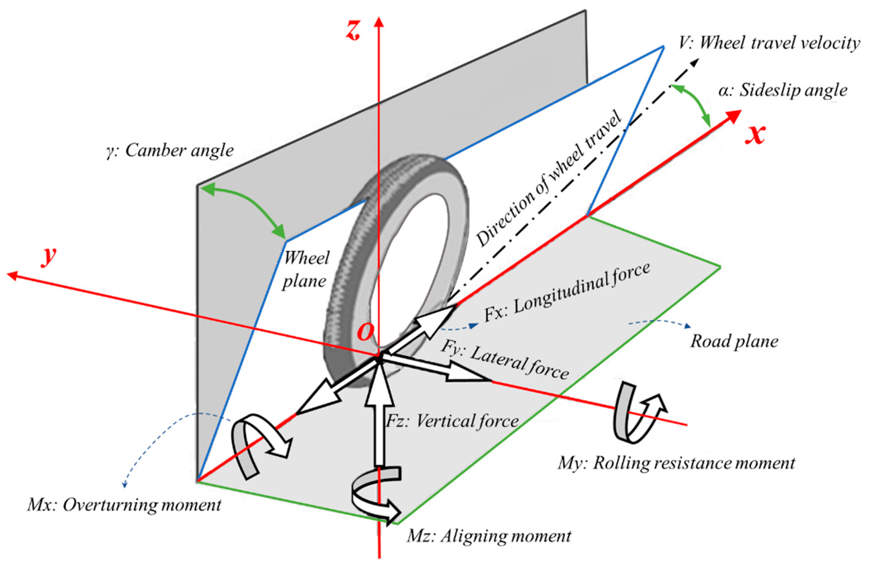
ISO coordinates were used to define the model parameters, as shown in Figure 1. The origin of coordinate O was the intersection point of the wheel plane and the ground. The intersecting line between the wheel plane and the ground was the x-axis and the forward direction was positive. The z-axis was perpendicular to the ground and was positive in the upward direction. The right-hand rule was used to determine the y direction.
The respective projections of the wheel travel velocity V on the x and y-axes were the longitudinal velocity Vx and the lateral velocity Vy, respectively. There is slippage in the longitudinal and lateral directions when braking in a turn. Vsx and Vsy represent the slip velocity in two directions and Vsy is equal to Vy, as shown in Figure 2. The longitudinal slip ratio κ and the slip angle α are defined as:
The tire kinematic parameters, ground forces, and torque are shown in Figure 1 and Figure 2. The tire model describes the relationship between the kinematics and the forces that are applied by the ground, as shown in Figure 3. There are several types of tire model: the Brush model, Magic Formula, UniTire, and Flexible Ring Tire Model. Most are for car tires. Unlike a car tire, a motorcycle tire apex has a large camber angle and a small sideslip angle during turning. The Magic Formula tire model is widely used because it features high precision and a uniform form. It is also suitable for motorcycle tires with a large camber angle [19,20]. This study uses Magic Formula PAC2012 to establish the tire model.
In Figure 3, longitudinal force directly determines the acceleration and braking deceleration and the lateral force significantly affects controllability and stability. When a motorcycle is braking on a curve, there is a longitudinal force and the road exerts a lateral force to counteract the centrifugal force, which is a feature of circular motion. This study uses the longitudinal and lateral characteristics of a motorcycle tire to determine the effect of specific parameters on the longitudinal and lateral forces.
If there is only longitudinal slip, the sideslip angle α is zero and the longitudinal force is expressed as:
In the above equation, Bx is the stiffness factor, Cx is the shape factor, Dx is the peak factor, and Ex is the curvature factor. The horizontal shift SHx and vertical shift SVx represent the effects of ply-steer, conicity, and the rolling resistance.
If there is combined slip, a weighting function is used to represent the interaction effect of the sideslip angle α on Fx. The longitudinal force for combined slip is:
If there is only sideslip, the longitudinal slip ratio κ is zero and the lateral force is expressed as:
For combined sideslip, a weighting function is used to represent the effect of the slip ratio κ on Fy. The lateral force in a combined sideslip situation is expressed as:
In Equations (3)–(6), the stiffness factor, the shape factor, the peak factor, and the curvature factor are affected by kinematic and dynamic parameters, such as the slip ratio, the sideslip angle, the camber angle, and the velocity. This study took a 180/55ZR17 motorcycle tire as the research object. The longitudinal and lateral characteristics were determined for different sideslip angle, longitudinal velocity, yaw rate, vertical load, and camber angle values. Diagrams of the longitudinal and lateral characteristics of a tire are shown in Figure 4 and Figure 5.
From the longitudinal characteristics of a tire in Figure 4, we could arrive at the conclusion that the slip ratio κ, the sideslip angle α, the travel velocity V, and the vertical load have significant effects on the longitudinal force, but the yaw rate and camber angle have little effect.
The lateral characteristics of a tire are shown in Figure 5. The slip ratio κ, the sideslip angle α, the vertical load, and the camber angle γ have significant effects on the lateral force, but the velocity and yaw rate have little effect on the lateral force. The last plot in Figure 5 shows that the greater the longitudinal force, the smaller the lateral force. The longitudinal and lateral forces are subject to a frictional ellipse.
The slip ratio κ, the sideslip angle α, and the vertical load affect the longitudinal and lateral characteristics; therefore, the longitudinal and lateral forces can be controlled by changing these three kinematic parameters. The slip ratio κ changes using the brake actuator, which controls the wheel speed. Therefore, the slip ratio κ is the input for the cornering braking control system that controls the longitudinal and lateral forces.
3. Optimization Model for the Best Slip Ratio
As shown in Figure 6, when a motorcycle is turning, there is a roll angle to offset the centrifugal force and maintain vehicle balance. This roll angle creates a camber angle for the tires. If a tire slides in the lateral direction, the vehicle becomes unstable and rolls, so there must be sufficient lateral force from the ground to allow a safe turn.
When a motorcycle brakes during a turn, a lateral force and a longitudinal force act on two wheels to brake the vehicle, so the longitudinal and lateral forces act on the tires concurrently. The longitudinal force is the braking force, which defines the braking performance, and the lateral force is related to the vehicle’s stability. The tire model for this study shows that the longitudinal and lateral forces are affected by the slip ratio, so these two forces are controlled by changing the slip ratio. An appropriate slip ratio provides the best braking efficiency and the vehicle is stable, so there is a constrained optimization problem for which the design variable is the slip ratio, the optimization object is to maximize the longitudinal braking force, and the constraint is that the lateral force must be sufficient to overcome the centrifugal force and ensure stability. In terms of the principle of force balance, the centrifugal force acting on a wheel is expressed as:
where FC is the centrifugal force and Fz is the vertical force. γ is the camber angle of the tire, and its value is approximately equal to the vehicle roll angle.
The mathematical expression for the constrained optimization problems is:
where κ* represents the best slip ratio and is the optimization result. κ is the current slip ratio. The possible value for the slip ratio κ is −1 to 0 during braking. If the slip ratio κ is −1, the wheel is locked. A slip ratio of zero denotes a freely rolling wheel. According to the longitudinal characteristic in Figure 4, the longitudinal force has unimodality in the slip ratio range of −1 to 0.
Given the unimodality, the gold section method was used to solve the optimization problem. The gold section method, or 0.618 method, is a tentative optimization method that uses the principle of interval elimination. By inserting two points to create an interval and computing these two function values, the interval is divided into three sections. By comparing these values, one of three sections is deleted so the region of the search is reduced in size. Two points are then inserted into the reduced interval and this process iterates until the interval is smaller than the convergence precision. The median of the final interval is the optimal solution. This study adds a step to determine whether the interval meets the constraints after inserting two points. The algorithm flow chart is shown in Figure 7.
The optimal slip ratio depends on the vertical force, the camber angle, the travel velocity, and the sideslip angle. For a sideslip angle of −2° and a wheel travel velocity of 100 km/h, the optimal slip ratio is shown in Figure 8. This value changes with the camber angle and the vertical force.
During braking, these four parameters change quickly. We plugged many sets of the tire parameter values into the optimization model and tabulated the results. The lookup table is shown in Figure 9. The input parameters were the vertical force, the camber angle, the travel velocity, and the sideslip angle, and the output was the optimal slip ratio. This 4-D lookup table shows the optimal slip ratio for the cornering braking controller during braking.
4. The Design of a Cornering Braking Control System
The controller structure is shown in Figure 10. There are three parts: an optimal slip ratio lookup table, a control system, and the motorcycle dynamics. It controls the motorcycle’s dynamic state and four dynamic parameters are used for the optimal slip ratio via the lookup table to determine the best slip ratio. The current slip ratio is fed back to the controller. The difference between the current and the best slip ratio is the input for the controller, which forms a closed-loop control to regulate the slip ratio for both tires.
A motorcycle is unstable when it is static. The roll angle can be 45 degrees during turning. This is a highly nonlinear, time-varying system. BikeSim is used to simulate the motorcycle’s dynamics. The control algorithm must learn, reason, and make decisions and adjustments to account for changes in the dynamic information. Artificial intelligence technology, such as fuzzy logic control, neural networks, self-adaptation, and so on, provides a theoretical basis.
Among them, the principle of fuzzy logic control is shown in Figure 11. This combines the artificial experience and knowledge in a database and a rule base. The controller can simulate the fuzzy reasoning and make decisions, similarly to humans, to give the control command to the controlled object. This control method is robust for a highly nonlinear system. However, the precision of fuzzy control greatly depends on the database and the rule base being tested repeatedly. It is also difficult to eliminate static errors.
To address the disadvantages of fuzzy control, a Fuzzy PID control strategy was used to control the motorcycle, which consisted of fuzzy logic and a PID controller. Owing to their simplicity and accuracy, PID controllers have been widely applied in many fields. However, for a nonlinear and hysteretic system whose mathematical model is unknown, a traditional PID controller cannot achieve good performance because it cannot adapt its parameters, including the proportionality, the integral, and the differential coefficient, if the process changes. Fuzzy logic provides an effective way to make PID adaptive. The principle of a fuzzy PID is shown in Figure 12. Fuzzy logic was used to adapt the PID parameters based on the error and error rate input, so the control parameter was self-learning and self-adjusting.
In order to test the effect of the proposed control system, this study applied the method of co-simulation via BikeSim and MATLAB. BikeSim, a mature motorcycle dynamics software, can perfectly simulate many kinds of motorcycle behavior conveniently, which offers a new approach to control and simulate complicated mechanisms. More importantly, BikeSim has an interface with MATLAB, which means it can exchange data with MATLAB. In this simulation experiment, a motorcycle tire and vehicle dynamics model was created, and the vehicle kinematic data were transferred to the MATLAB/Simulink environment. The braking control system, including the optimal slip ratio and Fuzzy PID controller, was established by Simulink and provided the control torque for two tires according to the vehicle’s kinematic parameters. As shown in Figure 13a, in the beginning, the motorcycle was turning with an initial speed of 100 km/h and an initial roll angle of 30°. After one second, the motorcycle began to brake during turning and the cornering braking control system started to work. The motorcycle dynamics parameters changed, as shown in Figure 13b–h.
The vertical forces (shown In Figure 13b), the camber angles (shown in Figure 13c), and the sideslip angles (shown in Figure 13d) changed, so the optimal slip ratio for both tires changed. The proposed control system automatically adjusted the optimal slip ratio. As shown in Figure 13e,f, the optimal slip ratios for the front tire and the rear tire were different because the tires had different kinematic parameters. The slip ratio followed the optimal slip ratio during braking to maintain the best braking performance.
As shown in Figure 13g,h, the roll angle decreased to about 0° and the speed also decreased to zero within 3.2 s, so the motorcycle stopped stably. When the velocity is very small, locking the tires is more effective than anti-lock braking. This control system had a velocity threshold value of 5 km/h, so the two tires were locked if the velocity was less than 5 km/h. Figure 13e,f,h shows that there was a sudden change in the slip ratio and the tire velocity in the fourth second because the vehicle’s velocity was less than 5 km/h. The sideslip angle for the tires was between −2° and 2°, so the direction stability was excellent during braking. These results solidly verify the feasibility of the proposed cornering braking control system.
According to tire dynamics analysis, in most cases, the maximum adhesion coefficient occurred at the slip ratio of −0.15 to −0.2, and a traditional anti-lock braking system always sets the reference slip ratio value between −0.15 and −0.2. For contrast, we applied a traditional ABS from [21], whose reference slip ratio was a fixed value of −0.15, to stop a turning motorcycle. The simulation conditions were the same as before: the initial speed was 100 km/h and the initial roll angle was 30°. After one second, it began to brake; the simulation results are shown in Figure 14. According to Figure 14a, the roll angle increased rapidly to about 80 degrees within 1 s, which meant that the motorcycle overturned suddenly. According to Figure 14b, due to insufficient lateral force, the sideslip angle of two tires changed on a large scale, which caused a side skid and overturn.
By comparing the braking performance of two braking control systems, it was proven that the proposed cornering braking control system could effectively maintain vehicle stability during cornering braking.
5. Conclusions
A motorcycle is a commonly used and convenient means of transportation in our daily life. Its inherent instability leads to hidden safety hazards during turning and braking. Therefore, it is meaningful to research and develop an active safety system for it. This study systematically analyzed the tire model characteristics and created an optimization procedure for the optimal slip ratio, and proposed a cornering braking control system based on Fuzzy PID. The control efficiency was verified by a co-simulation, and a comparative study was conducted with a traditional ABS. This research achieved the following:
1. The kinematic influences on the characteristic of a tire were identified: the slip ratio, the sideslip angle, and the vertical force could affect the longitudinal and lateral characteristics. The slip ratio was selected as the manipulated variable for the braking control system in consideration of its operability.
2. Based on the kinematic influences on tires, a constrained optimization model was created and solved. The obtained slip ratio was the optimal solution that could pursue excellent braking performance and ensure vehicle stability. It could change with the change in the motorcycle kinematic parameters, contributing to an improvement in the braking efficiency at any time.
3. The proposed cornering braking control system based on Fuzzy PID could perfectly follow the changing optimal slip ratio. The motorcycle would stop steadily and promptly, and the sideslip angles for the tires would be very small, meaning that the direction stability would be excellent during braking. The comparative study results verified the feasibility of the proposed cornering braking control system further.
The proposed braking control system required several motorcycle kinematic parameters, such as the roll angle, vehicle velocity, sideslip angle, and vertical forces. Obtaining these variables was the prior condition of the experiment. However, it is difficult to accurately measure some kinematic parameters directly using traditional sensors. For example, the roll angle, a crucial variable that determines a motorcycle’s behavior, need to be obtained via a state-estimation method. After obtaining the kinematic parameters via measurement or the state-estimation method, experiments should be conducted in the following research to test the proposed control system.
Author Contributions
Conceptualization, X.-D.Z. and C.-K.C.; methodology, X.-D.Z.; formal analysis, X.-D.Z.; investigation, C.-K.C.; writing—original draft preparation, X.-D.Z.; writing—review and editing, X.-D.Z. and C.-K.C.; supervision, C.-K.C. All authors have read and agreed to the published version of the manuscript.
Funding
This work was supported by the Ministry of Science and Technology of Taiwan, ROC, under grant number MOST 110-2622-E-027-008.
Institutional Review Board Statement
Not applicable.
Informed Consent Statement
Not applicable.
Data Availability Statement
Not applicable.
Acknowledgments
I would like to thank my supervisor, Chih-Keng Chen, for his guidance through each stage of the process.
Conflicts of Interest
The authors declare no conflict of interest.
References
- Savino, G.; Lot, R.; Massaro, M.; Rizzi, M.; Symeonidis, I.; Will, S.; Brown, J. Active safety systems for powered two-wheelers: A systematic review. Traffic Inj. Prev. 2020, 21, 78–86. [Google Scholar] [CrossRef] [PubMed] [Green Version]
- Sharp, R.S. The stability and control of motorcycles. J. Mech. Eng. Sci. 1971, 13, 316–329. [Google Scholar] [CrossRef] [Green Version]
- Sharp, R.S.; Limebeer, D.J. A motorcycle model for stability and control analysis. Multibody Syst. Dyn. 2001, 6, 123–142. [Google Scholar] [CrossRef]
- Limebeer, D.J.; Sharp, R.S.; Evangelou, S. The stability of motorcycles under acceleration and braking. Proc. Inst. Mech. Eng. Part C J. Mech. Eng. Sci. 2001, 215, 1095–1109. [Google Scholar] [CrossRef]
- Cossalter, V.; Lot, R. A Motorcycle Multi-Body Model for Real Time Simulations Based on the Natural Coordinates Approach. Veh. Syst. Dyn. 2002, 37, 423–447. [Google Scholar] [CrossRef]
- Cossalter, V. Motorcycle Dynamics, 2nd ed.; Lulu.com: Raleigh, NC, USA, 2006. [Google Scholar]
- Cossalter, V.; Lot Roberto, R.; Sartori, R.; Massaro, M. A motorcycle riding simulator for the improvement of the rider safety. In FISITA World Automotive Congress 2008, Congress Proceedings—Mobility Concepts, Man Machine Interface, Process Challenges, Virtual Reality; Citeseer: University Park, PA, USA, 2008; Volume 1, pp. 553–560. [Google Scholar]
- Cossalter, V.; Lot, R.; Massaro, M. An advanced multibody code for handling and stability analysis of motorcycles. Meccanica 2011, 46, 943–958. [Google Scholar] [CrossRef]
- Bonci, A.; De Amicis, R.; Longhi, S.; Lorenzoni, E.; Scala, G.A. Motorcycle’s lateral stability issues: Comparison of methods for dynamic modelling of roll angle. In Proceedings of the 2016 20th International Conference on System Theory, Control and Computing (ICSTCC), Sinaia, Romania, 13–15 October 2016; pp. 607–612. [Google Scholar]
- Costa, L.; Perrin, C.; Dubois-Lounis, M.; Serre, T.; M’Sirdi, N.K. Modelling of the powered two-wheeler dynamic behavior for emergency situations analysis. In Proceedings of the 16th International Conference Vehicle System Dynamics, Identification and Anomalies, Budapest, Hungary, 5–7 November 2018; pp. 231–238. [Google Scholar]
- Arricale, V.M.; Brancati, R.; Carputo, F.; Maiorano, A.; Dell’Annunziata, G.N. Non-linear Motorcycle Dynamic Model for Stability and Handling Analysis with Roll Motion and Longitudinal Speed Regulation. In Proceedings of the International Conference on Vehicle Technology and Intelligent Transport Systems, VEHITS, Online, 28–30 April 2021; Science and Technology Publications, LDA (SciTePress): Setubal, Portugal, 2021; Volume 2021, pp. 292–300. [Google Scholar]
- Jalti, F.; Hajji, B.; Mbarki, A. New Approach for Controlling PTW Vehicle Dynamics: Characterization of Critical Scenarios; Springer: Singapore, 2022; Volume 745. [Google Scholar]
- Tanelli, M.; Corno, M.; Boniolo, I.; Savaresi, S.M. Active braking control of two-wheeled vehicles on curves. Int. J. Veh. Auton. Syst. 2009, 7, 243–269. [Google Scholar] [CrossRef]
- De Filippi, P.; Tanelli, M.; Corno, M.; Savaresi, S.M.; Santucci, M.D. Electronic Stability Control for Powered Two-Wheelers. IEEE Trans. Control Syst. Technol. 2013, 22, 265–272. [Google Scholar] [CrossRef]
- Lich, T.; Block, W.G.; Prashanth, S.N.; Heiler, B. Motorcycle stability control-the next generation of motorcycle safety and riding dynamics. SAE Int. J. Engines 2016, 9, 491–498. [Google Scholar]
- Baumann, M.; Bächle, T.; Buchholz, M.; Dietmayer, K. Model-based corner braking control for electric motorcycles. IFAC-PapersOnLine 2016, 49, 291–296. [Google Scholar] [CrossRef]
- Melnikov, A.S.; Kim, V.A.; Melnikov, A.A. Increasing efficiency of braking control algorithm for a two-wheeled motorcycle. IOP Conf. Ser. Mater. Sci. Eng. 2020, 760, 012043. [Google Scholar] [CrossRef]
- Phalke, A.; Agrewale, M.R.B. Optimal brake force distribution in motorcycle for straight-line braking. Mater. Today Proc. 2022. [Google Scholar] [CrossRef]
- Pacejka, H. Tire and Vehicle Dynamics, 3rd ed.; Elsevier: Amsterdam, The Netherlands, 2012. [Google Scholar]
- Shang, Q.; Wang, G. Tire dynamics analysis based on PAC2002 Magic Formula. J. Beijing Inf. Sci. Technol. Univ. 2019, 34, 76–81. [Google Scholar]
- Dankan Gowda, V.; Ramachandra, A.C. Slip Ratio Control of Anti-Lock Braking System with Bang-Bang Controller. Int. J. Comput. Tech. 2017, 4, 97–104. [Google Scholar]
Figure 1.
Motorcycle tire coordinates and parameters.

Figure 2.
Tire velocity diagram.

Figure 3.
Input/output variables for the tire model.

Figure 4.
Longitudinal characteristics of a tire.


Figure 5.
Lateral characteristics of a tire.


Figure 6.
Force diagram for a motorcycle turning.

Figure 7.
Algorithm flow chart for the optimal slip ratio.

Figure 8.
Optimal slip ratio κ*.

Figure 9.
Optimal slip ratio lookup table.

Figure 10.
Block diagram for a cornering braking controller.

Figure 11.
Principle of fuzzy logic control.

Figure 12.
Fuzzy PID control system.

Figure 13.
Braking performance for optimal slip ratio input.


Figure 14.
Braking performance for a fixed slip ratio input.

Publisher’s Note: MDPI stays neutral with regard to jurisdictional claims in published maps and institutional affiliations. |
© 2022 by the authors. Licensee MDPI, Basel, Switzerland. This article is an open access article distributed under the terms and conditions of the Creative Commons Attribution (CC BY) license (https://creativecommons.org/licenses/by/4.0/).
Share and Cite
MDPI and ACS Style
Zhang, X.-D.; Chen, C.-K. A Study of a Cornering Braking Control System for a Motorcycle. Appl. Sci. 2022, 12, 12575. https://doi.org/10.3390/app122412575
AMA Style
Zhang X-D, Chen C-K. A Study of a Cornering Braking Control System for a Motorcycle. Applied Sciences. 2022; 12(24):12575. https://doi.org/10.3390/app122412575
Chicago/Turabian StyleZhang, Xiao-Dong, and Chih-Keng Chen. 2022. "A Study of a Cornering Braking Control System for a Motorcycle" Applied Sciences 12, no. 24: 12575. https://doi.org/10.3390/app122412575
Note that from the first issue of 2016, this journal uses article numbers instead of page numbers. See further details here.