
Process Stability Analysis during Trochoidal Milling of AZ91D Magnesium Alloy Using Different Toolholder Types

1
Department of Production Engineering, Mechanical Engineering Faculty, Lublin University of Technology, Nadbystrzycka 36, 20-618 Lublin, Poland
2
Department of Applied Mechanics, Faculty of Mechanical Engineering, Lublin University of Technology, Nadbystrzycka 36, 20-618 Lublin, Poland
3
Department of Manufacturing and Automation Technologies, Rzeszow University of Technology, Powstańców Warszawy 12, 35-959 Rzeszów, Poland
*
Author to whom correspondence should be addressed.
Appl. Sci. 2024, 14(9), 3616; https://doi.org/10.3390/app14093616
Submission received: 25 March 2024
/
Revised: 19 April 2024
/
Accepted: 22 April 2024
/
Published: 24 April 2024
(This article belongs to the Special Issue Processing, Manufacturing and Machining of Advanced Alloy Materials: Latest Advances and Prospects)
Abstract
:Featured Application
The conducted research constitutes valuable information for the manufacturing industry. Based on the obtained results, it is possible to select appropriate cutting conditions and equipment that allow for vibration reduction. This is an important issue because it improves the stability of machining processes, which may also result in an improvement in the quality of the manufactured parts. Vibrations mitigation also increases machining safety. The conducted research confirmed that the milling process of the AZ91D magnesium alloy can be carried out with relatively high stability over a wide range of cutting parameters.
Abstract
Trochoidal milling is one of the solutions for increasing the efficiency of machining processes. A decreased cutting tool’s arc of contact leads to a reduction in the generated cutting forces, thus improving process stability. Vibration is an inherent part of any machining process, affecting the accuracy and quality of the manufactured components, but it can also pose a danger to machine operators. Chatter is particularly detrimental, leaving characteristic marks on shaped surfaces and potentially leading to catastrophic tool damage. Therefore, it is important to ensure the stability of machining and also reduce vibration. The primary purpose of the conducted research is to evaluate the stability of the milling process of the AZ91D magnesium alloy performed through a trochoidal strategy. An additional objective is to establish the effect of the variation in machining parameters and toolholder types on milling stability. Three types of toolholders most commonly used in industry are used in the study. The basis of the investigation is the measurement of vibration displacement and acceleration analysed in the time domain. A spectral analysis of the signals is also performed based on Fast Fourier Transform, to identify signal components and detect the susceptibility to chatter occurrence. An important part of the study is also an attempt to use the Composite Multiscale Entropy as an indicator to determine the stability of the machining processes. Entropy does not exceed the values of 1.5 for cutting speed and 2.5 for feed per tooth, respectively. Vibration acceleration does not exceed (in most cases) the value of 20 m/s2 for the peak-to-peak parameter and the shrinkfit toolholder. For vibration displacement (peak-to-peak parameter), there are oscillations around the value of 0.9 mm for all kinds of toolholders.
1. Introduction
Chatter as a type of self-excited vibration constitutes some of the main impediments to the machining process. That vibration type can significantly affect the machining efficiency, destabilising the process and therefore significantly reducing both process and overall machining system reliability and safety. In critical circumstances, this could cause a loss of control of the entire manufacturing operation. The result can be the inability to obtain the required properties of the manufactured part (dimensional accuracy or surface quality) [1]. The described problem may occur during rough machining [2,3,4], while it may be particularly relevant during finishing [5] and precision and ultraprecision machining, especially for low-rigidity parts. There can be multiple causes of instability during machining. Among the most important and significant ones, the following are often mentioned [6,7]: varying undeformed chip thickness caused by vibration (trace regeneration phenomenon), the coupling of two natural modes of vibration, and excessive friction in the cutting zone at the contact area between the cutting tool and the machined layer of the workpiece. The vibration may result in characteristic marks (vibration effect between tool and workpiece), the so-called chatter marks, which usually results in a quality reduction in the machined surfaces [8,9]. In addition, vibration may cause adverse effects in the form of tool wear (reduced tool life), damage to the toolholders and even the entire machining assemblies (as a result of high vibration amplitudes), and health hazards for machine operators (as a result of excessive noise and its high frequencies) [10,11,12].
The presence of vibrations, unfortunately, quite often necessitates a limitation of the applied machining parameters, and thus considerably reduces the productivity of the machining and consequently increases the time of manufacturing. In order to avoid this, diverse methods of vibration reduction are applied. Paper [13] presents different ways and types of damping of chatter vibration, and also includes a description of damping method selection with regard to the machinability of the workpiece and machining system rigidity, that is, the different conditions existing during machining. In the Stability Lobe Diagram (SLD), it is possible to consider tool diameter importance, as a bigger tool diameter can positively extend the stable areas. Moreover, it is also advantageous to use tools with a greater number of cutting edges, as this can result in an increase in the usable range of rotational speed (shifting the SLD to the right) [14,15]. Unfortunately, the use of SLD plots also has some disadvantages. Among the most commonly mentioned ones are the static approach to input data acquisition and the creation of SLD curves, during the standstill of the machining machine. Such a test therefore does not consider the key process dynamics parameters of the spindle system (for example, thermal expansion or system stiffness), or various other factors related to the characteristics of the workpiece (for example, changes in undeformed chip thickness cross-section, material defects, or damping properties) [13,16]. The process stability studies often also use [17,18] spectra analysis, the Poincare method, and the chase plane method, which allows, e.g., to discuss the relationship between the milling parameters and the maximum Lyapunov exponent. Using the Lyapunov exponent criterion, it is possible to determine the vibration stability zone for machining operations (0.61 in this case). An interesting analysis was also performed in paper [7], where external forcing was used to enable the control of the milling process. Tests and numerical analyses were executed with the use of the Runge–Kutta method. The susceptibility of the tool and workpiece to vibration and other non-linear phenomena was considered. An SLD was determined and an analysis of the influence of external forcing was performed. In addition, a proportional–integral controller was used to make closed-loop control possible. The application of the presented methodology allowed for the observation of a decrease in vibration levels during machining.
Trochoidal milling is a machining strategy that involves the cutting tool’s movement along circular paths. This method is much less popular than the commonly used milling along straight paths. The current development of software and control systems for machining centres enables a much simpler generation of these types of paths. A significant advantage of this milling strategy is mainly the reduced load on the cutting tool, which periodically goes in and out of the workpiece material. It also reduces the cutting force and temperature generated during cutting. This can significantly extend the tool’s life, as well as increasing process stability. In [19], the effect of changing two parameters, specifically the cutting speed and trochoid pitch, on the cutting forces and vibration acceleration and displacement was analysed. Selected surface roughness parameters (Sa and Sz) were also presented for comparison. The magnesium alloys used in this study were AZ91D and AZ31. The research findings indicated a significant impact of cutting speed on the components of cutting force as well as machining vibration. Simulations with artificial neural networks were also performed in this study. Meanwhile, in [20], a trochoidal milling study was performed using the popular EN-AW 7075-T651 aluminium alloy. Chip thickness and cutting force modelling were analysed for the low speed range. Current chip thickness was related to the actual cutting force, which demonstrated quite good correlation with the simulated results. A similar study was performed in [21], where the trochoidal milling of EN-AW 7075-T651 and the cutting force coefficients were analysed. The outcomes revealed that lower values of cutting force components were obtained using trochoidal milling than slotting. An analysis of aluminium alloys, specifically the EN-AW 7039 alloy, was also carried out in [22]. To increase the efficiency of trochoidal milling, a double trochoidal milling path was used. An analytical model was created to determine engagement, which enabled the prediction of the cutting forces. Additionally, a numerical model of the engagement was developed. In all applications, the results indicated a good correlation between the measured and predicted forces. In [23], the five-axis rough trochoidal machining of the EN-AW 5086 aluminium alloy was analysed. Two interpolation models were examined and evaluated (trochoidal and zigzag toolpaths). In this study, maximum values of the cutting force component were recorded. The research results obtained from the simulation and the experiment were very close, which validated the correctness of the proposed approach. This attitude led to a slight overestimation, but the calculation times were very short (a rapid assessment of tool load and a rapid selection of toolpath parameters). Paper [24] presented the trochoidal milling of the EN-AW 2024 and EN-AW 6082 aluminium alloys. Selected surface roughness parameters were analysed. Some interdependencies between roughness parameters, torque, and cutting forces were observed. Varying radial depth of cut and two different machining strategies were used in the study. Meanwhile, paper [25] involved the use of the EN-AW 6061-T6 alloy. It conducted a simulation based on a coupled Eulerian–Lagrangian method and a verification of the trochoidal milling processes was performed. The presented model exhibited quite good suitability for predicting the cutting force (error within 12%). It also gave highly reliable predictions about chip morphology. A continuous remeshing algorithm was omitted, providing information on contact forces and interfacial stresses.
Considering the above review of scientific research on the stability evaluation during machining, there are certain deficiencies regarding the broader analysis. However, in recent years, there has been a slight trend of scientific interest in such research and subsequent publications. For instance, in paper [26], the material removal mechanism was evaluated while micro-milling the AZ31B magnesium alloy. It was noticed that the machining mechanism was affected by vibration frequency. However, these studies are only concerned with the milling process referred to as micro-milling, and hence it is difficult to extrapolate and compare with traditional rough or finishing processes performed in typical industrial-grade production procedures. A significant amount of available research is focused on the analysis of the machining stability of aluminium alloys [27,28,29,30,31]. On the other hand, difficult-to-machine materials are very popular in scientific research [32,33]. Research in the field of magnesium alloys is performed much less often and is carried out along standard straight paths [34,35,36]. Moreover, publications mainly only concern the analysis of vibration amplitude. It is quite evident that this approach is rather inadequate for describing machining vibration. The number of publications concerning the impact of toolholder types on the occurrence of vibration during magnesium alloy machining is also very limited. This state of knowledge indicates a continuing need to improve and expand expertise on the milling stability of magnesium alloys.
The AZ91D magnesium alloy is used in many industries. Most often, it is employed in the automotive and aviation industries, but other industries, such as the sports industry, electronics, and computing, also make use of this alloy. For example, the AZ91D alloy can be used to produce elements such as gear housings, small cockpit elements, car rims, car engine components, laptop and telephone casings, and bicycle or motorcycle frames.
A major novelty of the performed study is the application of a trochoidal strategy to the machining of magnesium alloy. Based on the completed literature review, that strategy has not yet been thoroughly analysed in relation to this group of materials. However, it enables a significant increase in the milling process efficiency and a reduction in cutting temperature, which is crucial when it comes to safety for magnesium alloys, which are prone to ignition. This study extensively investigates machining stability based on the different parameters and the tools used for signal analysis. The main goal of this research was to determine how the trochoidal strategy affects the stability of the machining of the AZ91D magnesium alloy. An additional objective was to analyse the influence of the toolholder type on vibrations during trochoidal milling. When using different types of holders, the stability may differ in relation to machining the magnesium alloy along straight paths.
2. Materials, Methods, and Experiment Procedure
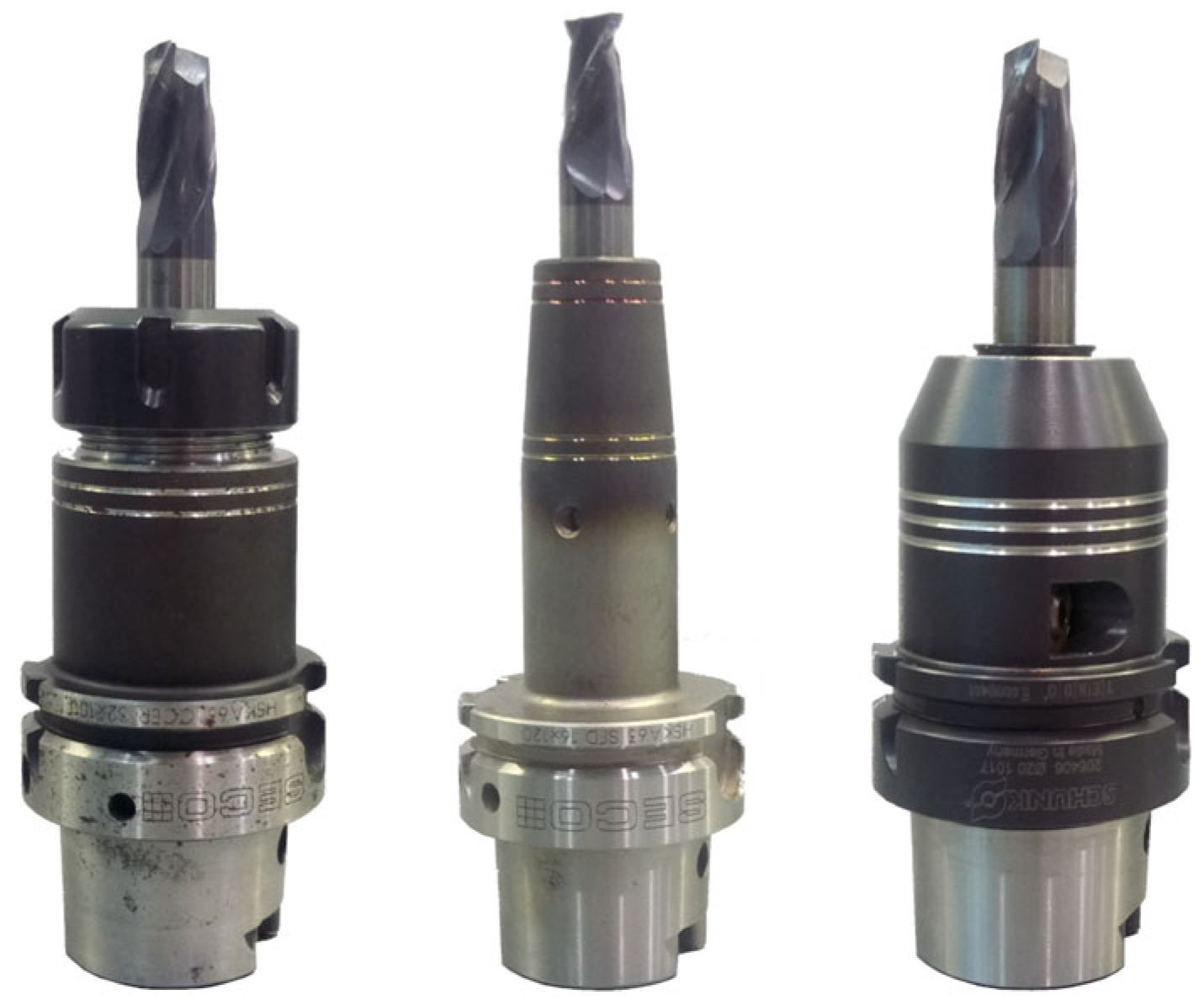
The workpiece material examined during this study was the AZ91D (MgAl9Zn1) magnesium alloy. Milling operations were realised on an AVIA VMC 800 HS milling centre. Three different types of HSK-A63 toolholders were tested: ER, shrinkfit, and hydraulic toolholders. The unbalance of the holder–tool set was verified on a CIMAT RT 610 balancing machine according to the ISO 21940-11 standard [37].
A view of the toolholders with the mounted cutting tool is shown in Figure 1.
The research was performed at variable milling parameters including a cutting speed vc = 400–1000 m/min and feed per tooth fz = 0.05–0.30 mm/tooth, while the axial depth of cut ap = 6 mm and the radial depth of cut ae = 25 mm were constant. This parameter selection was determined by the milling centre spindle speed, experience in magnesium alloys machining, and the generated Stability Lobe Diagrams. A carbide end mill with TiAlN coating was selected for the realisation of the milling tests. The tool had a diameter of 16 mm and two cutting edges. The machining process was conducted through a trochoidal strategy. Siemens NX 10 software was used to generate the toolpaths and the trochoidal pitch was set at 15%. A view of the generated trochoidal toolpaths is shown in Figure 2.
During machining tests, vibration measurements were taken in the feed direction. The vibration sensors used were the optoNCDT LD1605-2 laser sensor (displacement measurements) and the PCB 352B10 accelerometer (acceleration measurements). Vibration sensors are characterised by their high universality and ease of application. The accelerometer was fixed directly in the centre of the front surface of the machined workpiece. The laser beam of the displacement sensor was also directed at the same front surface of the workpiece. This sensor was positioned at a distance of less than 2 mm from the workpiece. CutPro 9 software was used to generate SLDs based on the signal recorded with the modal hammer.
The signals registered during machining were analysed according to the following indicators: peak-to-peak and root mean square (RMS). The value of the peak-to-peak indicator was determined as the difference between the maximum and minimum values of the recorded vibrations signal. The RMS values of the vibration displacement and acceleration were determined according to Equations (1) and (2).
where x(t)—displacement; a(t)—acceleration; and T—time.
The Composite Multiscale Entropy (CMSE) algorithm, which enables a detailed insight into its concept and computational steps, was described extensively in [38]. It is an enhanced solution to other methods based on the entropy phenomenon used so far. The complete calculation procedure was carried out in Matlab R2019b software.
3. Results and Discussion
The milling process was preceded by a modal analysis to determine stable zones. The SLDs generated for individual toolholders with mounted cutting tool are shown in Figure 3.
The course of the curves differed for individual toolholders. Nevertheless, for all toolholder types, the stability limit was approx. 6 mm, which was comparable with the applied depth of cut ap. On this basis, it can be concluded that chatter should not occur during machining, or its impact should be relatively low, which allows the milling process to be carried out safely without a loss of stability. At a low spindle speed n, the curves are most dense, which increases the risk of chatter vibration, while at a higher spindle speed, the spaces between the curves significantly increase, making it easier to reach a region of greater stability. Analysing the obtained curves, it can be concluded that the least risk of chatter vibration with the applied technological parameters will occur when using a hydraulic toolholder, as it mostly fits the stable areas of the curves.
Figure 4 shows example signals of vibration displacement and acceleration obtained when applying a hydraulic toolholder.
The displacement signal has a similar course to the signals usually recorded during conventional straight-path milling. No abrupt changes of value are apparent in the signal waveform and it is distributed approximately symmetrically. However, the course of the vibration acceleration signal significantly differs in shape. It shows systematic amplitude peaks due to the cyclic tool entering into the sample. After the tool has exited the workpiece, the magnitude of the signal significantly decreases.
3.1. Vibration Displacement Analysis
The signals acquired during machining were considered according to peak-to-peak and RMS indicators. The resulting parameter values for different toolholder types, depending on the change in technological parameters, are shown in Figure 5 and Figure 6.
Increasing the cutting speed led to a progressive growth in both peak-to-peak and RMS values, irrespective of which type of toolholder was applied. At the highest cutting speed vc = 1000 m/min, a minor reduction in peak-to-peak values was also observed when using the shrinkfit and hydraulic toolholders. At the minimum cutting speed, the lowest vibration displacement occurred using the ER toolholder, while within vc = 600–1000 m/min, the lowest values for both parameters were obtained using the hydraulic toolholder. Regardless of a change in cutting speed, the highest vibration displacement occurred when using the shrinkfit toolholder.
When changing the feed per tooth, the trend in parameter changes was less conclusive. The peak-to-peak parameter values obtained when machining with the ER and hydraulic toolholders increased as a result of increasing the feed within fz = 0.05–0.15 mm/tooth, while decreasing thereafter. In case of the shrinkfit toolholder, the decrease in values only occurred at the highest feed. The lowest peak-to-peak values were achieved in most cases using the ER toolholder. For the RMS parameter, the trend in changes due to a varying feed per tooth was inconclusive, irrespective of the toolholder used. Within fz = 0.05–0.20 mm/tooth, indicator values were similar for all toolholders, while for the highest feed values, the ER toolholder proved to be the most beneficial one.
Comparing the obtained results with other studies carried out on magnesium alloys showed that higher vibration displacement values were obtained during trochoidal milling. The differences were not relatively large, but machining along straight paths proved more advantageous.
3.2. Vibration Acceleration Analysis
The effect of the change in cutting parameters and toolholder types on vibration acceleration is shown in Figure 7 and Figure 8. A change in cutting speed caused a roughly linear rise in peak-to-peak and RMS values, irrespective of the toolholder type in which the tool was mounted. However, several times lower values were obtained with the shrinkfit toolholder, which was also sensitive to changes in cutting speed.
A similar relationship was observed when milling with variable feed per tooth. Peak-to-peak and RMS values progressively increased throughout the range of feed change. Once again, the smallest values were observed using the shrinkfit toolholder, whose change due to feed variation was small. For the other toolholders, several times higher parameter values were obtained, and their increase due to increase in feed was much greater.
The outcome of the investigations demonstrates that the implementation of trochoidal milling made it possible to obtain comparable or even lower values of vibration acceleration than in the case of magnesium alloy milling along straight paths, previously described in other papers.
3.3. Composite Multiscale Entropy (CMSE) Analysis
The signals registered during the experimental studies were also subjected to Composite Multiscale Entropy (CMSE) analysis. Using this method, dynamic experimental signals can be verified. The entropy level determines the degree of disorder in the measured signals. The findings of the analysis by this method are given in Figure 9, Figure 10, Figure 11 and Figure 12.
The CMSE was determined for τ = 50; however, due to the lack of apparent variation in the further scale factor range, the plot area was restricted to τ = 0–20. The concept of CMSE is based on the coarse-graining procedure that uses a coarse-grained time series, as an average of the original data points within non-overlapping windows by increasing the scale factor τ. The length of each coarse-grained time series is N⁄τ. For τ = 1, the coarse-grained time series is simply the original time series itself. From a practical point of view, for τ < 20, the error made is very small and does not affect the accuracy of the determined CMSE value.
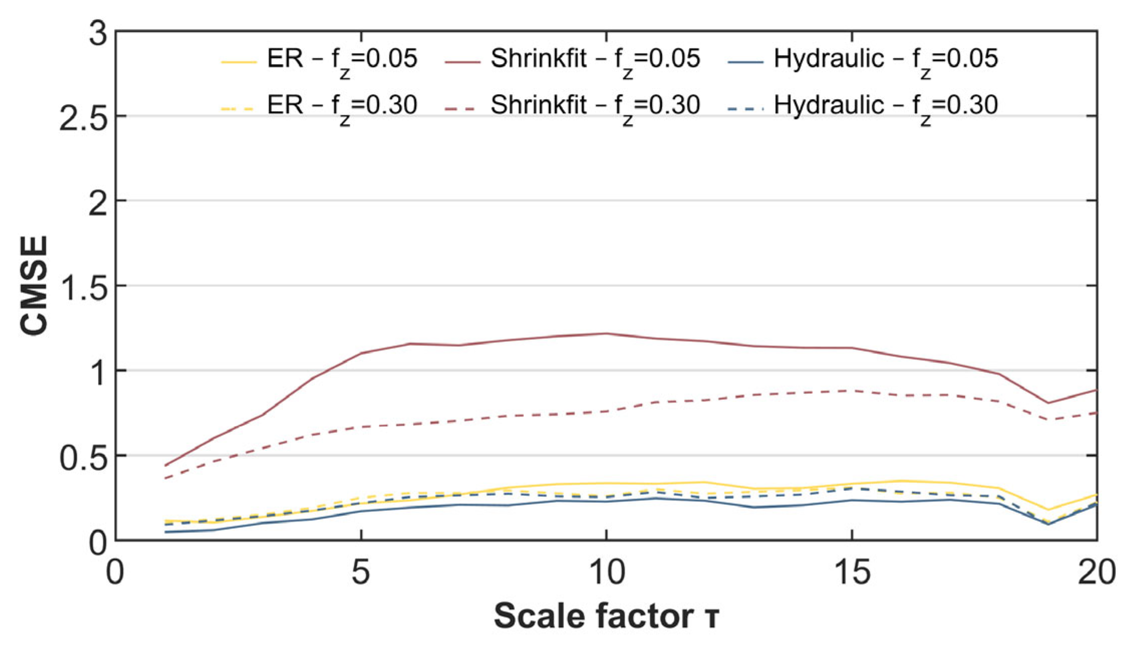
In the first instance, the displacement signals were analysed considering the impact of cutting speed vc (Figure 9) and feed per tooth fz (Figure 10). In both cases, a significantly lower level of CMSE was observed when milling with an ER toolholder. In contrast, the highest level of CMSE was obtained using the shrinkfit toolholder, which is particularly evident above τ = 10. The level of CMSE was practically equal for the displacement signals recorded during milling with the ER and hydraulic toolholders. Changing the cutting speed vc did not alter this trend. It was also observed that the increase in cutting speed vc causes a reduction in entropy level, which implies an increase in the ordering of the signal. This phenomenon was observed for all three toolholders used in the experiment. This phenomenon is particularly beneficial as it provides more stable cutting conditions.
A similar behaviour of the Composite Multiscale Entropy level was observed when the feed fz was increased (Figure 10). However, a trend of displacement signal ordering increase with increasing feed per tooth fz was only found for milling with the use of the ER and hydraulic toolholder types. By analysing the displacement signal in the case of milling with the shrinkfit toolholder, it may be concluded that changing the feed value had almost negligible impact on the CMSE level in the analysed parameter range.
The acceleration signals were further analysed also considering the influence of the cutting speed vc (Figure 11) and the feed per tooth fz (Figure 12). In both cases, it was observed that a significantly higher level of CMSE was obtained when the milling process was performed with the shrinkfit toolholder. The other two toolholders used in this study exhibited similar (lower) levels of Composite Multiscale Entropy.
Changing the cutting speed vc can significantly affect the reduction in the entropy level when the acceleration signal of the shrinkfit test toolholder is analysed (Figure 11). The other two toolholders exhibited a lower effect of changing the cutting speed vc, although this was noticeable. As well as displacement signal analysis, the beneficial effects of the increased cutting speed vc on the stability of the milling process were also apparent. Increasing the feed fz value had the strongest effect on the change in level of CMSE for the shrinkfit toolholder (Figure 12). To a small extent, such changes could be observed for the ER and hydraulic toolholders. However, the use of the ER and hydraulic toolholder types was much more favourable in this case due to the significantly lower level of signal disorder compared to the shrinkfit toolholder. The presented results lead to the conclusion that the ER and hydraulic toolholder types can be used over a wider range of feed per tooth fz changes with stability maintained during the milling process.
Comparing vibration displacement and acceleration signals, a significantly lower level of Composite Multiscale Entropy was observed for the latter. The higher level of CMSE in the case of the displacement signal is a consequence of the milling strategy (trochoidal milling). The acceleration signal reflects the rapidity of the milling process dynamics. A lower level of CMSE for the acceleration signal indicates a more stable milling process. Thus, in the context of the signal analysis carried out using Composite Multiscale Entropy, it can be concluded that trochoidal milling shows a lower abruptness of dynamic changes. This has a more advantageous effect on the stability of the milling process.
3.4. Fast Fourier Transform (FFT) Analysis
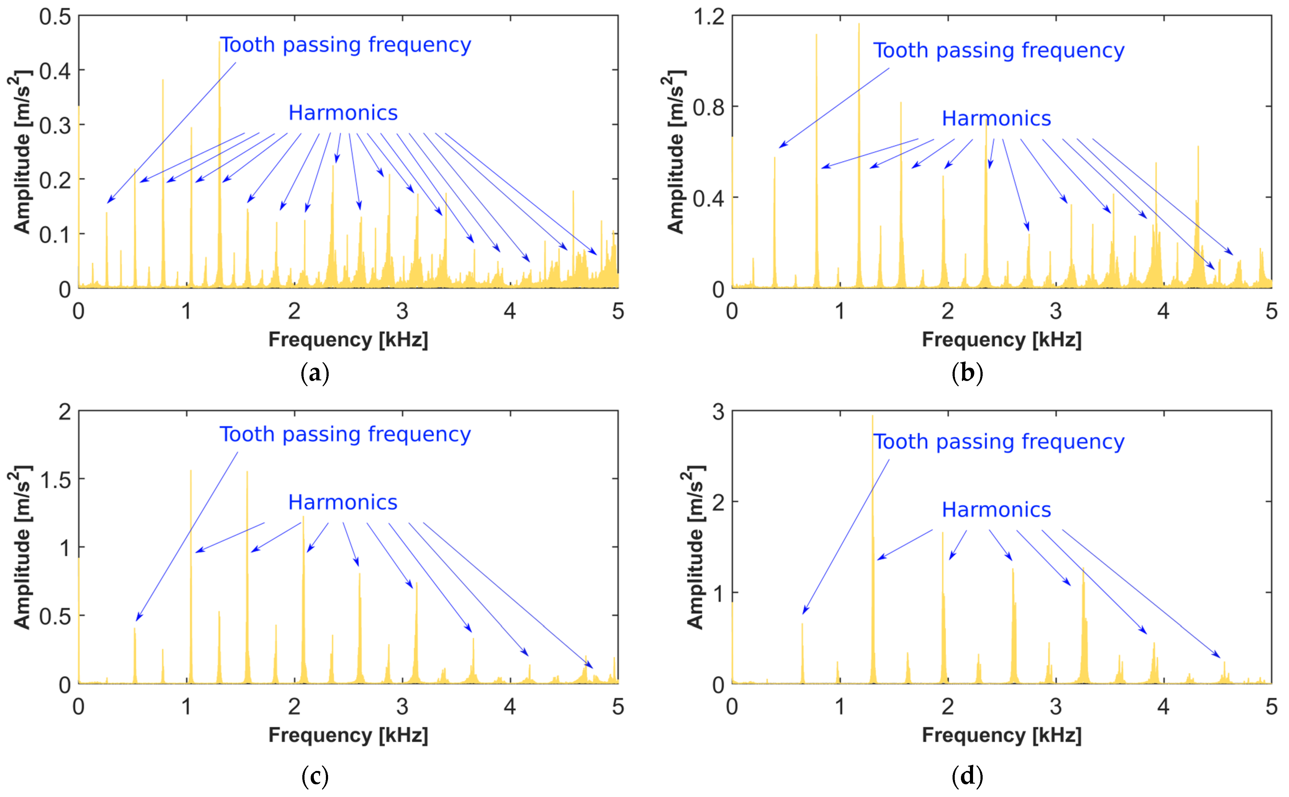
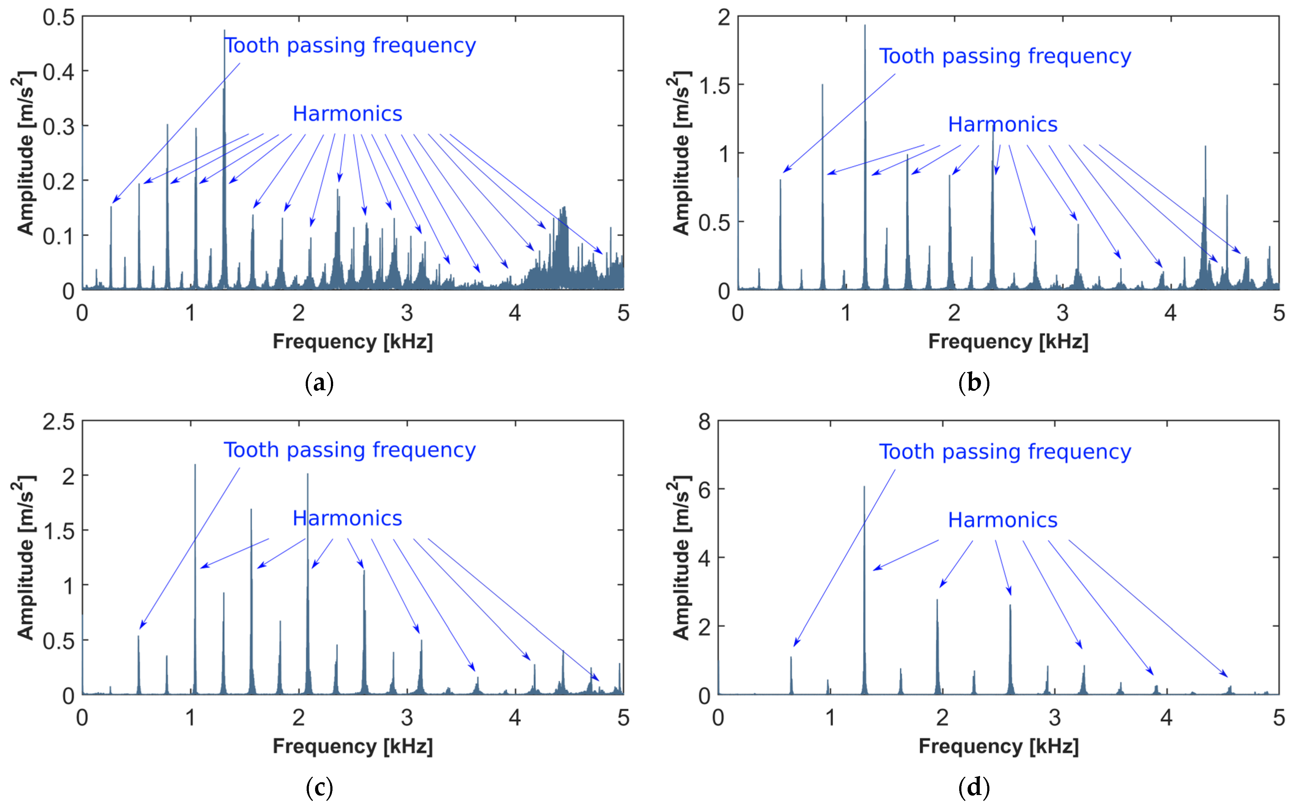
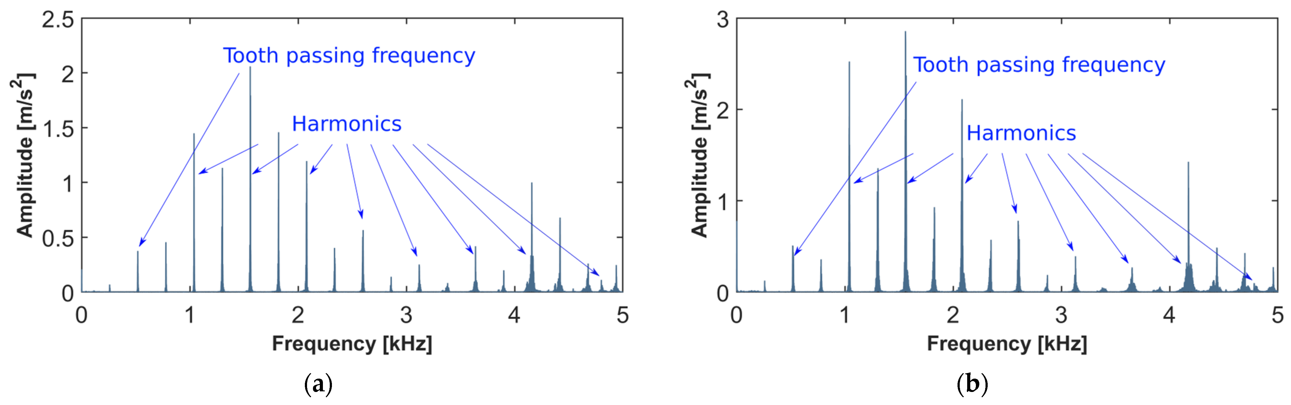
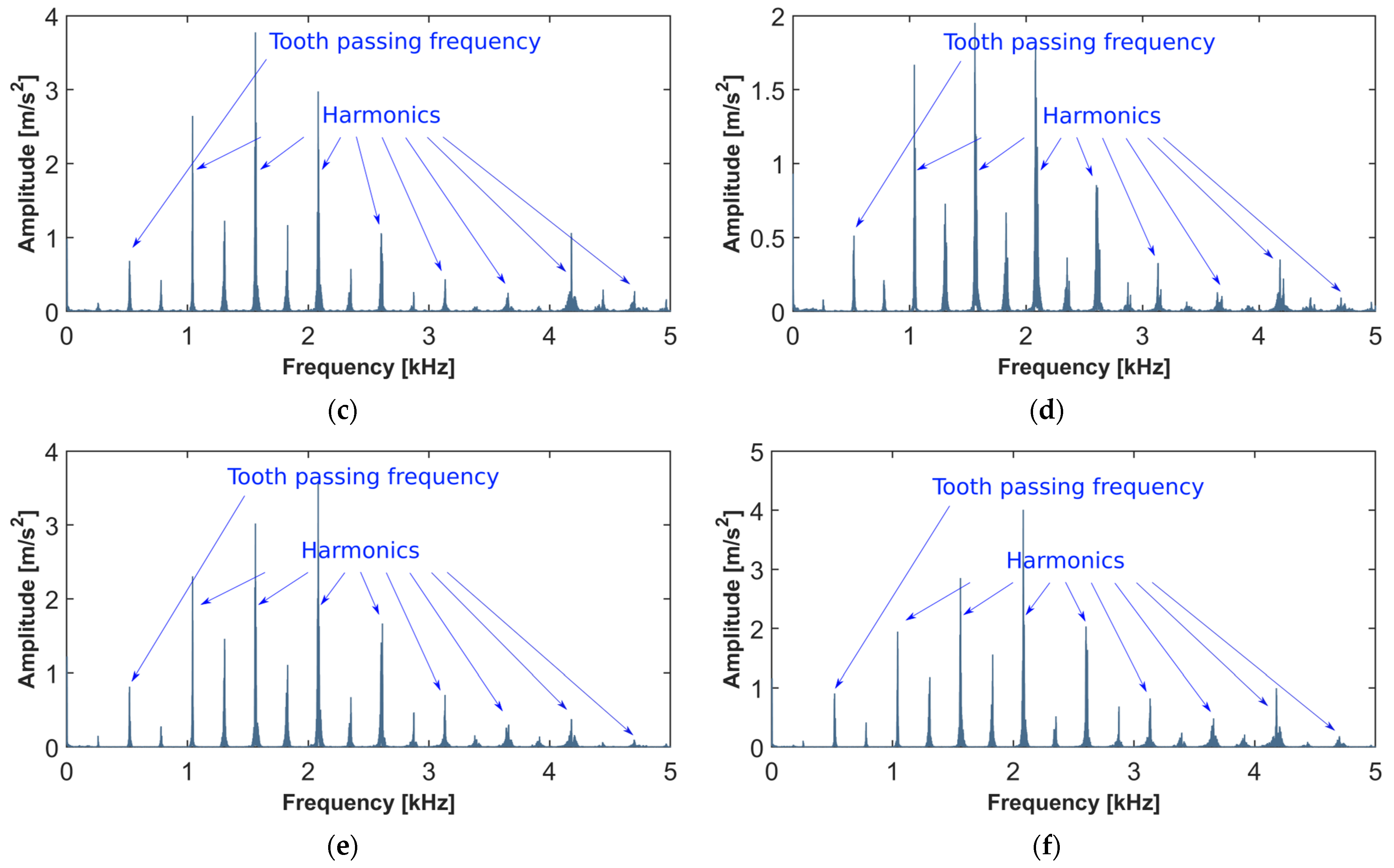
Acceleration signals acquired during machining were analysed in the frequency domain by applying a Fast Fourier Transform (FFT). This enables the determination of the frequencies at which the components of the vibration signal occur. This approach facilitates the detection of chatter vibration that is a potential risk during the milling process. The analysis was carried out for signals obtained when changing the cutting speed (Figure 13, Figure 14 and Figure 15) and feed per tooth (Figure 16, Figure 17 and Figure 18). Tooth passing frequencies and harmonics, which are multiplications of tooth passing frequencies, were marked on the obtained diagrams and are presented in Table 1.
On the waveforms achieved for milling with the ER toolholder (Figure 13), the largest peaks occurred at frequencies corresponding to harmonics. These are multiples of the tooth passing frequencies, which correspond to the considered cutting speeds, namely, 265, 398, 531, and 663 Hz, respectively. At a lower cutting speed vc = 400–600 m/min, an initial decrease in harmonics amplitude height was observed, followed by a subsequent increase. This indicates some instability in the process and a tendency towards self-excited vibration. At a higher cutting speed vc = 800–1000 m/min, harmonics were gradually extinguished, but the amplitudes at other frequencies also increased. However, their values were not very high, so machining can be considered fairly stable. When increasing cutting speed, the amplitude of vibration magnitude also increased.
The harmonics were dominant again when machining was performed with the tool clamped in the shrinkfit toolholder (Figure 14), except vc = 800 m/min, where the passing frequency had the highest peak. Their amplitudes gradually decreased at higher frequencies. The exception was the harmonics at vc = 400 m/min, where the amplitudes again increased around 3 kHz, but the increase was relatively slight. Within the range vc = 800–1000 m/min, peaks also appeared at frequencies other than the harmonics and their values were lower than the harmonics. However, they were higher than the results obtained when using the ER holder. There was no clear effect of changing the cutting speed on the magnitude of the vibration as the maximum amplitudes were comparable at cutting speeds vc = 600 and 1000 m/min, which may be associated with the fact that these speeds were in the unstable machining area of the SLD. The amplitude decreased at vc = 800 m/min, as that speed was at the limit of the stable machining area.
In the case of the hydraulic toolholder (Figure 15), the greatest difference could be seen at the lowest cutting speed, where the number of frequencies at which chatter occurred was considerably higher compared to the other toolholders. This indicates a fairly high susceptibility to the chatter vibration occurrence. Machining stability considerably improved at the other cutting speed vc, where vibration occurred at fewer frequencies and was gradually weakened. At a cutting speed vc = 800–1000 m/min, amplitudes at non-harmonics frequencies could also be seen, but their value was several times lower. With increasing cutting speed, the magnitude of the vibration also increased and was the highest of all the toolholders used, especially at the highest cutting speed.
From the conducted analysis, it can be considered that the obtained results corresponded fairly well with the predictions that could be made from the SLDs (Figure 1). When the milling process was carried out at cutting speeds that were in the unstable machining area, there was a temporary increase in the vibration magnitude. However, if the assumed technological parameters were in the stable machining area, increasing the cutting speed caused a gradual growth in vibration amplitude.
The rotational speed did not change when the feed per tooth was changed, and therefore the tooth passing frequency was approximately 531 Hz for all cases. When using the ER toolholder (Figure 16), the amplitude value on the tooth passing frequencies was much lower than the harmonics, similarly as for cutting speed changing. In most cases, a gradual extinction of the subsequent harmonics could be observed as the frequency increased. Amplitudes at frequencies that are not multiples of the tooth passing frequencies can also be seen in the charts, but their values were much lower than the harmonics, indicating relatively good process stability. There was also an increase in the vibration magnitude as the feed increased, but the change was very slight within the range fz = 0.15–0.30 mm/tooth.
In contrast to the other toolholder types, when using the shrinkfit toolholder (Figure 17), the peak heights at the tooth passing frequencies were comparable to the harmonics. In most cases, the highest amplitudes occurred at the frequency corresponding to the second harmonic, but in the further frequency range, the vibration spectrum became extinct. Amplitudes at frequencies other than harmonics can also be seen on the chart. These were only slightly lower than the harmonics, which is probably related to the very low values of the vibration amplitude, which were several times lower than when using the ER and hydraulic toolholders. In addition, the change in feed had no great effect on machining stability, as the change in vibration magnitude due to an increase in feed was negligible.
When using a hydraulic toolholder (Figure 18), the tooth passing frequencies were also again lower than the initial harmonics. The largest peaks appeared at the second harmonic for a feed fz = 0.05–0.20 mm/tooth and the third harmonic for a feed fz = 0.25–0.30 mm/tooth, indicating a certain tendency for vibration occurrence. However, the amplitudes gradually decreased in the further range. A renewed increase in vibration magnitude occurred above 4 kHz, but this was relatively small, especially at higher feed values. The recorded amplitude values were the highest of all the toolholders used, rising to the highest values at the highest feed per tooth.
The research conducted so far mainly concerned milling using straight tool paths. The influence of the type of toolholder during the milling of magnesium alloys was previously analysed for AZ91D [34] and AZ31B [35]. The test results contained in [34] carried out for the AZ91D alloy allowed for the formulation of important conclusions: all values of the vibration displacement and acceleration increased with the cutting speed and feed per tooth (except vc 1000 m/min—a decrease in the vibration displacement). For a heat shrink holder, several times lower values of the vibration acceleration and the lowest entropy value. For vc 400 m/min, the lowest values of vibration displacement and amplitude (below 0.02 mm) were observed. However, an increase in fz caused an increase in the value of vibration displacement and amplitudes. For the range 0.05–0.2 mm/tooth, the vibration displacement range and amplitudes were equal to approx. 0.015–0.025 mm. The maximum values of vibration acceleration were the lowest for vc 400 m/min and for heat shrink chuck—4.9 m/s2. The lowest ay vibration values were obtained for fz 0.05 mm/tooth, and for heat shrink chuck—5.7 m/s2. However, in the case of the AZ31B alloy [35], it was observed that the increase in vc and fz had a significant impact on the vibrations. A vibration increase with an increasing vc (approx. linear) was observed; however, fz caused the greatest increase in vibrations, especially visible and noticeable for vibration acceleration. A relatively low level of signal irregularity for CMSE was observed, and the value of vibration acceleration entropy decreased for higher values of the scale factor. During FFT analysis, a high stability of milling processes was observed; however, for the highest vc and low fz, the process showed susceptibility to chatter vibration. However, the use of trochoidal paths [19] when milling with a tool with a shrink holder allowed us to notice that with the increase in cutting speed, the values of the analysed machinability indicators decreased. Better stability and milling effectiveness (lower values of vibrations) were obtained for high-speed machining (vc 1000–1200 m/min). The character of vibrations depends on the milling parameters; moreover, stable milling conditions may be obtained by increasing the vc and reducing the trochoidal step.
4. Conclusions
Trochoidal milling is an appealing machining strategy for increasing the process efficiency. As indicated by the performed studies, it may be effectively employed for the machining of the AZ91D magnesium alloy. The milling process can be considered as relatively stable, since the vibration generated during its performance is low. Furthermore, the following conclusions could be derived from the achieved results:
- The changes in cutting speed and feed per tooth have substantial impact on the displacement and acceleration of machining vibration generated during the milling process. This applies to both the intensity of the vibration and the sensitivity of the process on their appearance. The selection of appropriate machining parameters can therefore significantly increase the stability and safety of milling.
- Considering vibration displacement, the ER or hydraulic toolholder is the most favourable type (depending on the change in technological parameters), while when analysing the vibration acceleration, the most beneficial type is the shrinkfit toolholder. The advantages of using the shrinkfit toolholder were also observed when analysing the signals in the frequency domain, as it generated the lowest vibration magnitude and was the least sensitive type to changes in cutting parameters.
- Based on the analysis of the signals using Composite Multiscale Entropy, it can be concluded that trochoidal milling exhibits less abrupt changes in dynamics, which has good influence on the stability of the cutting process.
- It was observed that increasing the cutting speed causes a reduction in the Composite Multiscale Entropy level, which implies an increase in signal ordering. Milling performed at a higher cutting speed vc therefore has a positive impact on the machining process’ stability. That phenomenon was observed for all three toolholders used. The ER and hydraulic toolholders can be applied over a wider range of feed per tooth while maintaining stability in milling processes.
- The increase in cutting speed caused an increase in amplitude, as well as a decrease in the number of the harmonic frequencies at which peaks occurred. At the highest cutting speed, vibration occurred only at frequencies resulting from the tooth passing frequency and its harmonics. A similar behaviour occurred when changing the feed per tooth.
- The results of the FFT analysis corresponded reasonably well with the information available from the generated Stability Lobe Diagram. This confirms that with their use, it is possible to pre-determine the machining condition under which an unfavourable vibration should not occur.
- The results of displacement and vibration acceleration measurements varied considerably, and therefore the selection of a suitable measurement sensor is of particular importance.
- Entropy did not exceed the values of 1.5 for cutting speed and 2.5 for feed per tooth, respectively. Vibration acceleration did not exceed (in most cases) the value of 20 m/s2 for the peak-to-peak parameter and the shrinkfit toolholder. For vibration displacement (peak-to-peak parameter), there were oscillations around the value of 0.9 mm for all kinds of toolholders.
The trochoidal strategy yielded satisfactory results. Nevertheless, further research is required to fully assess its benefits. In subsequent studies, it is planned to apply trochoidal machining to other magnesium alloys. Not only vibration but also other machinability indices will need to be investigated and evaluated.
Author Contributions
Conceptualization, J.K. and I.Z.; methodology, J.K., I.Z. and A.W.; software, J.K.; validation, J.K., I.Z., A.W. and W.H.; formal analysis, J.K., I.Z., A.W. and W.H.; investigation, J.K., I.Z. and A.W.; resources, I.Z. and A.W.; data curation, J.K.; writing—original draft preparation, J.K., I.Z., A.W. and W.H.; writing—review and editing, J.K., I.Z., A.W. and W.H.; visualization, J.K.; supervision, J.K. and I.Z.; project administration, J.K. and I.Z.; funding acquisition, I.Z. All authors have read and agreed to the published version of the manuscript.
Funding
The research leading to these results has received funding from the commissioned task entitled “VIA CARPATIA Universities of Technology Network named after the President of the Republic of Poland Lech Kaczyński” contract no. MEiN/2022/DPI/2575 action entitled “In the neighborhood-inter-university research internships and study visits”.
Data Availability Statement
The data presented in this study are available on request from the corresponding author. The data are not publicly available due to restrictions of the study being on-going.
Conflicts of Interest
The authors declare no conflicts of interest.
References
- Yue, C.; Gao, H.; Liu, X.; Liang, S.Y.; Wang, L. A review of chatter vibration research in milling. Chin. J. Aeronaut. 2019, 32, 215–242. [Google Scholar] [CrossRef]
- Salehi, M.; Blum, M.; Fath, B.; Akyol, T.; Haas, R.; Ovtcharova, J. Epicycloidal Versus Trochoidal Milling-Comparison of Cutting Force, Tool Tip Vibration, and Machining Cycle Time. Procedia CIRP 2016, 46, 230–233. [Google Scholar] [CrossRef]
- Niaki, F.A.; Pleta, A.; Mears, L.; Potthoff, N.; Bergmann, J.A.; Wiederkehr, P. Trochoidal milling: Investigation of dynamic stability and time domain simulation in an alternative path planning strategy. Int. J. Adv. Manuf. Technol. 2019, 102, 1405–1419. [Google Scholar] [CrossRef]
- Oleksik, M.; Dobrota, D.; Tomescu, M.; Petrescu, V. Improving the Performance of Steel Machining Processes through Cutting by Vibration Control. Materials 2021, 14, 5712. [Google Scholar] [CrossRef] [PubMed]
- Seguy, S.; Insperger, T.; Arnaud, L.; Dessein, G.; Peigné, G. On the stability of high-speed milling with spindle speed variation. Int. J. Adv. Manuf. Technol. 2009, 48, 883–895. [Google Scholar] [CrossRef]
- Quintana, G.; Ciurana, J. Chatter in machining processes: A review. Int. J. Mach. Tools Manuf. 2011, 51, 363–376. [Google Scholar] [CrossRef]
- Weremczuk, A.; Rusinek, R.; Warmiński, J. The concept of active elimination of vibrations in milling process. Procedia CIRP 2015, 31, 82–87. [Google Scholar] [CrossRef]
- Dikshit, M.K.; Puri, A.B.; Maity, A. Chatter and dynamic cutting force prediction in high-speed ball end milling. Mach. Sci. Technol. 2017, 21, 291–312. [Google Scholar] [CrossRef]
- Biermann, D.; Kersting, P.; Surmann, T. A general approach to simulating workpiece vibrations during five-axis milling of turbine blades. CIRP Ann. 2010, 59, 125–128. [Google Scholar] [CrossRef]
- Bejaxhin, A.B.H.; Paulraj, G. Experimental investigation of vibration intensities of CNC machining centre by microphone signals with the effect of TiN/epoxy coated tool holder. J. Mech. Sci. Technol. 2019, 33, 1321–1331. [Google Scholar] [CrossRef]
- Dimla, E.; Dimla, S. Sensor signals for tool-wear monitoring in metal cutting operations—A review of methods. Int. J. Mach. Tools Manuf. 2000, 40, 1073–1098. [Google Scholar] [CrossRef]
- Jauregui, J.C.; Resendiz, J.R.; Thenozhi, S.; Szalay, T.; Jacso, A.; Takacs, M. Frequency and Time-Frequency Analysis of Cutting Force and Vibration Signals for Tool Condition Monitoring. IEEE Access 2018, 6, 6400–6410. [Google Scholar] [CrossRef]
- Munoa, J.; Beudaert, X.; Dombovari, Z.; Altintas, Y.; Budak, E.; Brecher, C.; Stean, G. Chatter suppresion techniques in metal cutting. CIRP J. Manuf. Sci. Technol. 2016, 65, 785–808. [Google Scholar] [CrossRef]
- Hsiao, T.C.; Huang, S.C. The Effect of Cutting Process Parameters on the Stability in Milling. Adv. Mater. Res. 2014, 887, 1200–1204. [Google Scholar] [CrossRef]
- Ahmadi, K.; Ismail, F. Analytical stability lobes including nonlinear process damping effect on machining chatter. Int. J. Mach. Tools Manuf. 2011, 51, 296–308. [Google Scholar] [CrossRef]
- Le Lan, J.V.; Marty, A.; Debongnie, J.F. Providing stability maps for milling operations. Int. J. Mach. Tools Manuf. 2007, 47, 1493–1496. [Google Scholar] [CrossRef]
- Wu, S.; Li, R.; Liu, X.; Yang, L.; Zhu, M. Experimental study of thin wall milling chatter stability nonlinear criterion. Procedia CIRP 2016, 56, 422–427. [Google Scholar] [CrossRef]
- Lauro, C.H.; Brandao, L.C.; Baldo, D.; Reis, R.A.; Davim, J.P. Monitoring and processing signal applied in machining processes—A review. Measurement 2014, 58, 73–86. [Google Scholar] [CrossRef]
- Zagórski, I.; Kulisz, M.; Kłonica, M.; Matuszak, J. Trochoidal Milling and Neural Networks Simulation of Magnesium Alloys. Materials 2019, 12, 2070. [Google Scholar] [CrossRef]
- Pleta, A.; Niaki, F.A.; Mears, L. Investigation of chip thickness and force modelling of trochoidal milling. Procedia Manuf. 2017, 10, 612–621. [Google Scholar] [CrossRef]
- Pleta, A.; Niaki, F.A.; Mears, L. A comparative study on the cutting force coefficient identification between trochoidal and slot milling. Procedia Manuf. 2018, 26, 570–579. [Google Scholar] [CrossRef]
- Otkur, M.; Lazoglu, I. Trochoidal milling. Int. J. Mach. Tools Manuf. 2007, 47, 1324–1332. [Google Scholar] [CrossRef]
- Rauch, M.; Duc, E.; Hascoet, J.Y. Improving trochoidal tool paths generation and implementation using process constraints modelling. Int. J. Mach. Tools Manuf. 2009, 49, 375–383. [Google Scholar] [CrossRef]
- Józwik, J. Analysis of the Effect of Trochoidal Milling on the Surface Roughness of Aluminium Alloys after Milling. Manuf. Technol. 2019, 19, 772–779. [Google Scholar] [CrossRef]
- Gao, Y.; Ko, J.H.; Lee, H.P. 3D Eulerian Finite Element Modelling of End Milling. Procedia CIRP 2018, 77, 159–162. [Google Scholar] [CrossRef]
- Chen, W.; Zheng, L.; Teng, X.; Yang, K.; Huo, D. Finite element simulation and experimental investigation on cutting mechanism in vibration-assisted micro-milling. Int. J. Adv. Manuf. Technol. 2019, 105, 4539–4549. [Google Scholar] [CrossRef]
- Burek, J.; Żyłka, L.; Płodzień, M.; Gdula, M.; Sułkowicz, P. The influence of the cutting edge shape on high performance cutting. Aircr. Eng. Aerosp. Technol. 2018, 90, 134–145. [Google Scholar] [CrossRef]
- Zawada-Michałowska, M.; Kuczmaszewski, J.; Pieśko, P. Influence of pre-machining on post-machining deformation of thin-walled elements made of aluminium alloy EN AW-2024. IOP Conf. Ser. Mater. Sci. Eng. 2018, 393, 012100. [Google Scholar] [CrossRef]
- Yusoff, A.R. Identifying bifurcation behavior during machining process for an irregular milling tool geometry. Measurement 2016, 93, 57–66. [Google Scholar] [CrossRef]
- Sivasakthivel, P.S.; Velmurugan, V.; Sudhakaran, R. Prediction of vibration amplitude from machining parameters by response surface methodology in end milling. Int. J. Adv. Manuf. Technol. 2011, 53, 453–461. [Google Scholar] [CrossRef]
- Karkalos, N.E.; Karmiris-Obratański, P.; Kurpiel, S.; Zagórski, K.; Markopoulos, A.P. Investigation on the Surface Quality Obtained during Trochoidal Milling of 6082 Aluminum Alloy. Machines 2021, 9, 75. [Google Scholar] [CrossRef]
- Kluz, R.; Habrat, W.; Bucior, M.; Krupa, K.; Sęp, J. Multi-criteria optimization of the turning parameters of Ti-6Al-4V titanium alloy using the Response Surface Methodology. Eksploat. I Niezawodn.–Maint. Reliab. 2022, 24, 668–676. [Google Scholar] [CrossRef]
- Li, N.; Chen, Y.; Kong, D. Effect of cutter body geometry in Ti-6Al-4V face-milling process. Int. J. Adv. Manuf. Technol. 2019, 100, 1881–1892. [Google Scholar] [CrossRef]
- Zagórski, I.; Korpysa, J.; Weremczuk, A. Influence of Tool Holder Types on Vibration in Rough Milling of AZ91D Magnesium Alloy. Materials 2021, 14, 2517. [Google Scholar] [CrossRef] [PubMed]
- Korpysa, J.; Zagórski, I. Vibration analysis during AZ31 magnesium alloy milling with the use of different toolholder types. Eksploat. I Niezawodn.–Maint. Reliab. 2022, 24, 489–501. [Google Scholar] [CrossRef]
- Gobivel, K.; Vijay Sekar, K.S. Influence of cutting parameters on end milling of magnesium alloy AZ31B. Mater. Today Proc. 2022, 62, 933–937. [Google Scholar] [CrossRef]
- ISO 21940-11:2016; Mechanical Vibration—Rotor Balancing—Part 11: Procedures and Tolerances for Rotors with Rigid Behavior. ISO: Geneva, Switzerland, 2016.
- Rusinek, R.; Borowiec, M. Stability analysis of titanium alloy milling by multiscale entropy and Hurst exponent. Eur. Phys. J. Plus 2015, 130, 194. [Google Scholar] [CrossRef]
Figure 1.
View of ER, shrinkfit, and hydraulic toolholders with mounted cutting tool.

Figure 2.
View of trochoidal toolpaths.

Figure 3.
Stability Lobe Diagram for different toolholders.

Figure 4.
(a) Vibration displacement and (b) vibration acceleration signals.

Figure 5.
(a) Peak-to-peak and (b) RMS values for vibration displacement with different cutting speeds.
Figure 5.
(a) Peak-to-peak and (b) RMS values for vibration displacement with different cutting speeds.

Figure 6.
(a) Peak-to-peak and (b) RMS values for vibration displacement with different feed per tooth.
Figure 6.
(a) Peak-to-peak and (b) RMS values for vibration displacement with different feed per tooth.

Figure 7.
(a) Peak-to-peak and (b) RMS values for vibration acceleration with different cutting speeds.
Figure 7.
(a) Peak-to-peak and (b) RMS values for vibration acceleration with different cutting speeds.

Figure 8.
(a) Peak-to-peak and (b) RMS values for vibration acceleration with different feed per tooth.
Figure 8.
(a) Peak-to-peak and (b) RMS values for vibration acceleration with different feed per tooth.

Figure 9.
CMSE for displacement signals registered with different cutting speeds.

Figure 10.
CMSE for displacement signals registered with different feed per tooth.

Figure 11.
CMSE for acceleration signals registered with different cutting speeds.

Figure 12.
CMSE for acceleration signals registered with different feed per tooth.

Figure 13.
FFT for a cutting speed of (a) 400 m/min, (b) 600 m/min, (c) 800 m/min, and (d) 1000 m/min, applying the ER toolholder.
Figure 13.
FFT for a cutting speed of (a) 400 m/min, (b) 600 m/min, (c) 800 m/min, and (d) 1000 m/min, applying the ER toolholder.

Figure 14.
FFT for a cutting speed of (a) 400 m/min, (b) 600 m/min, (c) 800 m/min, and (d) 1000 m/min, applying the shrinkfit toolholder.
Figure 14.
FFT for a cutting speed of (a) 400 m/min, (b) 600 m/min, (c) 800 m/min, and (d) 1000 m/min, applying the shrinkfit toolholder.

Figure 15.
FFT for a cutting speed of (a) 400 m/min, (b) 600 m/min, (c) 800 m/min, and (d) 1000 m/min, applying the hydraulic toolholder.
Figure 15.
FFT for a cutting speed of (a) 400 m/min, (b) 600 m/min, (c) 800 m/min, and (d) 1000 m/min, applying the hydraulic toolholder.

Figure 16.
FFT for a feed of (a) 0.05 mm/tooth, (b) 0.1 mm/tooth, (c) 0.15 mm/tooth, (d) 0.2 mm/tooth, (e) 0.25 mm/tooth, and (f) 0.3 mm/tooth, applying the ER toolholder.
Figure 16.
FFT for a feed of (a) 0.05 mm/tooth, (b) 0.1 mm/tooth, (c) 0.15 mm/tooth, (d) 0.2 mm/tooth, (e) 0.25 mm/tooth, and (f) 0.3 mm/tooth, applying the ER toolholder.

Figure 17.
FFT for a feed of (a) 0.05 mm/tooth, (b) 0.1 mm/tooth, (c) 0.15 mm/tooth, (d) 0.2 mm/tooth, (e) 0.25 mm/tooth, and (f) 0.3 mm/tooth, applying the shrinkfit toolholder.
Figure 17.
FFT for a feed of (a) 0.05 mm/tooth, (b) 0.1 mm/tooth, (c) 0.15 mm/tooth, (d) 0.2 mm/tooth, (e) 0.25 mm/tooth, and (f) 0.3 mm/tooth, applying the shrinkfit toolholder.

Figure 18.
FFT for a feed of (a) 0.05 mm/tooth, (b) 0.1 mm/tooth, (c) 0.15 mm/tooth, (d) 0.2 mm/tooth, (e) 0.25 mm/tooth, and (f) 0.3 mm/tooth, applying the hydraulic toolholder.
Figure 18.
FFT for a feed of (a) 0.05 mm/tooth, (b) 0.1 mm/tooth, (c) 0.15 mm/tooth, (d) 0.2 mm/tooth, (e) 0.25 mm/tooth, and (f) 0.3 mm/tooth, applying the hydraulic toolholder.


Table 1.
Tooth passing frequencies and harmonics.
| vc [m/min] | Frequencies [Hz] | ||||||||||||||||
|---|---|---|---|---|---|---|---|---|---|---|---|---|---|---|---|---|---|
| 400 | 265 | 530 | 795 | 1060 | 1325 | 1590 | 1855 | 2120 | 2385 | 2650 | 2915 | 3180 | 3445 | 3710 | 3975 | 4240 | 4505 |
| 600 | 398 | 796 | 1194 | 1592 | 1990 | 2388 | 2786 | 3184 | 3582 | 3980 | 4378 | 4776 | |||||
| 800 | 531 | 1062 | 1593 | 2124 | 2655 | 3186 | 3717 | 4248 | 4779 | ||||||||
| 1000 | 663 | 1326 | 1989 | 2652 | 3315 | 3978 | 4641 | ||||||||||
Disclaimer/Publisher’s Note: The statements, opinions and data contained in all publications are solely those of the individual author(s) and contributor(s) and not of MDPI and/or the editor(s). MDPI and/or the editor(s) disclaim responsibility for any injury to people or property resulting from any ideas, methods, instructions or products referred to in the content. |
© 2024 by the authors. Licensee MDPI, Basel, Switzerland. This article is an open access article distributed under the terms and conditions of the Creative Commons Attribution (CC BY) license (https://creativecommons.org/licenses/by/4.0/).
Share and Cite
MDPI and ACS Style
Korpysa, J.; Zagórski, I.; Weremczuk, A.; Habrat, W. Process Stability Analysis during Trochoidal Milling of AZ91D Magnesium Alloy Using Different Toolholder Types. Appl. Sci. 2024, 14, 3616. https://doi.org/10.3390/app14093616
AMA Style
Korpysa J, Zagórski I, Weremczuk A, Habrat W. Process Stability Analysis during Trochoidal Milling of AZ91D Magnesium Alloy Using Different Toolholder Types. Applied Sciences. 2024; 14(9):3616. https://doi.org/10.3390/app14093616
Chicago/Turabian StyleKorpysa, Jarosław, Ireneusz Zagórski, Andrzej Weremczuk, and Witold Habrat. 2024. "Process Stability Analysis during Trochoidal Milling of AZ91D Magnesium Alloy Using Different Toolholder Types" Applied Sciences 14, no. 9: 3616. https://doi.org/10.3390/app14093616
Note that from the first issue of 2016, this journal uses article numbers instead of page numbers. See further details here.