.jpg)
Corrosion and Protection of Magnesium Alloys: Recent Advances and Future Perspectives

School of Materials Science and Engineering, Shanghai University of Engineering Science, Shanghai 201620, China
*
Author to whom correspondence should be addressed.
Coatings 2023, 13(9), 1533; https://doi.org/10.3390/coatings13091533
Submission received: 10 June 2023
/
Revised: 20 August 2023
/
Accepted: 30 August 2023
/
Published: 1 September 2023
(This article belongs to the Special Issue Surface Function Enhancement of Energy Storage Materials)
Abstract
:Magnesium alloys are of significant importance for lightweight manufacturing and weight-saving applications due to their high weight-to-strength ratio and good mechanical properties. However, the poor corrosion resistance of Mg alloys limits their large-scale practical application. An essential theoretical foundation for the development of corrosion-resistant magnesium alloys and their surface protection technologies can be elucidated via the investigation of the corrosion mechanism of the magnesium surface and the alteration of the corrosion rate after surface conversion and coating. This paper discusses some typical corrosion behaviors by originally describing the corrosion mechanism of magnesium alloys with and without different coatings and surface treatments. In order to predict the future theoretical investigation and research directions for the surface protection of magnesium alloys, some techniques and preventative measures to enhance the corrosion resistance of magnesium alloys are reviewed, and these protection techniques are intercompared for better understanding.
1. Introduction
In the 21st century, with the improvement and development of technological productivity, researchers gradually realized the importance of environmental protection and proper utilization of resources [1,2,3]. There is a great emphasis on the cleanliness of energy, the reusability of resources, and lightweight and structural integration in the modern manufacturing industry. Magnesium and its alloys have garnered significant interest under these circumstances. In comparison to other commonly used metal materials, magnesium alloys possess a lightweight property, with a density of approximately 2/3 of aluminum and 1/4 of steel, and their high machinability and damping ability give magnesium alloys excellent working performance, which is an ideal choice for lightweight manufacturing. In the field of medical devices, magnesium alloys have a similar Young’s modulus to human bone and exhibit better biocompatibility, osteoinductivity, and self-degradability, offering great prospects for the future [4,5]. In addition, magnesium alloys have excellent welding performance, good heat dissipation performance, and recyclability [6,7].
Magnesium is abundantly available in China, which is also a significant global exporter of metal. Magnesium alloy processing and application have great potential in future industries such as automobiles, aerospace, and energy [8]. However, magnesium metal is naturally active due to its intrinsic electron configuration. At room temperature, it is prone to being oxidized and can react with water to release hydrogen [9]. The chemical properties of magnesium alloys determine their low hardness and poor corrosion resistance, both of which are significant drawbacks that restrict their widespread application [10,11,12]. On the basis of these points, this study focuses on the corrosion behaviors and related mechanisms of magnesium alloys and presents the current advancements in research to increase the corrosion resistance of magnesium alloys in recent years.
2. Corrosion Types of Magnesium Alloys
The standard potential of magnesium is −2.37 V [13], which is lower than that of iron and aluminum (Table 1). As a result, it is extremely susceptible to the formation of a magnesium oxide film on its surface when exposed to air. This film is loose and porous, and it cannot protect the magnesium substrate as completely as the aluminum oxide film on Al alloys.
Magnesium alloys are prone to hydrogen evolution and corrosion behavior when exposed to a humid environment [9]. Hydrogen ion reduction and cathodic hydrogen overpotential play a major role in the corrosion process of magnesium alloys. The anodic and cathodic reactions in the corrosion process are as follows:
Anode: Mg (s) + 2OH− → Mg (OH)2 (s) + 2e−
Cathode: 2H2O + 2e− → H2 (g) + 2OH−
Magnesium alloys suffer from more complicated transitional changes during the actual corrosion process. The main corrosion types include general corrosion, local corrosion, galvanic corrosion, and stress corrosion cracking. Galvanic corrosion is the general mode of magnesium alloy corrosion, and stress corrosion cracking is a failure form of corrosion and the environment together.
2.1. General Corrosion
When an electrochemical reaction between magnesium alloys and water occurs, the Mg matrix dissolves during the corrosion process, and a layer of hydroxide film is formed on the surface, accompanied by the generation of hydrogen gas [14]. The process of general corrosion is uniform and normally occurs on the surface of the material. The formed film layer exhibits a hexagonal structure [15]. Magnesium ions and hydroxide ions are alternately arranged in the crystal structure, but the connection between them is not close enough. Therefore, it is easy for the film to crack and has a limited protective ability on the substrate. Compared with other forms of corrosion, the uniformity of general corrosion makes it less harmful to magnesium alloys [16]. The general corrosion products of magnesium alloys are related to the chemical composition of magnesium alloys and the corrosion environment.
2.2. Local Corrosion
Local corrosion of magnesium alloys is more destructive to the substrate than general corrosion due to the difference in corrosion rate in various parts, and local corrosion of magnesium alloys includes pitting corrosion and filiform corrosion [17,18,19].
The surface of magnesium alloys usually contains the second phase, impurities, etc. When magnesium alloys are exposed to corrosive environments, the corrosive medium crosses the surface film and comes into direct contact with the substrate, where pitting corrosion occurs in these areas [20]. Therefore, corrosion is concentrated in a localized area on the surface. The formation of pitting corrosion is closely related to grain size, solution environment, chemical composition, and the second phase. Typically, the finer the grain structure, the fewer pittings there are. The uniform and fine equiaxed grains of AZ31B magnesium alloy were obtained by the stationary shoulder friction stir processing process, which made the corrosion mode of the magnesium alloy change from pitting corrosion to general corrosion, and the corrosion resistance was improved [21]. Magnesium alloys are susceptible to salt solution, especially salt solution containing Cl−. Due to the small diameter and high permeability of Cl−, it is easy for it to damage the surface coating and cause local electrochemical corrosion to form pitting corrosion. The occurrence of pitting corrosion is also related to the PH of the solution. It is generally believed that an alkaline environment (PH > 10.5) is more conducive to inhibiting the occurrence of pitting corrosion.
Filiform corrosion of magnesium alloys usually occurs under the surface oxide film and protective coatings [22]. There are many factors affecting the filiform corrosion of magnesium alloys, including the corrosion medium, microstructure, oxide film, and so on. Corrosion is usually caused by the defects of the corrosive medium preferentially adsorbed in the naturally formed oxide film on the surface of magnesium alloys. The distribution of precipitates and alloying elements lead to the initiation of corrosion at these locations, which may develop in different directions. The second phase has a significant effect on filiform corrosion. The extension direction of filiform corrosion is related to the difference between the matrix and the second phase. The corrosion behavior of ZK60 magnesium alloy in NaCl aqueous solution was studied. The results showed that the filiform corrosion originated from the second-phase particles, MgZn2, deposited along the grain boundary and then propagated around the grain boundary [23]. The microstructure of filiform corrosion can be divided into two parts: the anodic front and the cathodic tail. The potential difference between its head and tail is regarded as the driving force for corrosion expansion [24] (Figure 1). The microstructure of the alloy has a great influence on filiform corrosion. The microscale polarization technique was used to observe the filiform corrosion of AZ91D magnesium alloy in NaCl solution. It was found that filiform corrosion mainly appeared and expanded in the α + β phase of the layered structure. Less filiform corrosion was observed in the α phase grains, but no trace of filamentary corrosion was observed in the β phase [25].
2.3. Galvanic Corrosion
Galvanic corrosion is an electrochemical corrosion that occurs when two metals or alloys with different electrode potentials contact each other or pass through other media under natural conditions. It is also called bimetallic corrosion or contact corrosion [26,27]. Generally, the metal with the lower electrode potential will show a significant increase in the corrosion rate, and the metal with a higher electrode potential will show a slower corrosion rate. The greater the difference between the electrode potentials of the two metals, the more obvious the corrosion characteristics are [28]. In general, when galvanic corrosion occurs between magnesium alloys and other metals, the electrode potential, effective contact area, and environmental conditions will affect the galvanic corrosion behavior. Due to the low corrosion potential of magnesium alloys, it often acts as an active anode in the primary battery system and is preferentially corroded. A study showed that the area ratio of the cathode to anode was proportional to the rate of galvanic corrosion. As the area ratio expanded, the current density also increased [26]. The application of magnesium alloys in chemically active environments faces significant challenges due to galvanic corrosion.
There are second phases and some impurities in magnesium alloys, which lead to various electrochemical activities and produce micro-scale thermocouples. Usually, the second phase or impurities in the alloy act as the cathode of corrosion due to the high potential, while the magnesium-rich phase acts as the anode, forming a galvanic pair and generating a corrosion current. The extent of damage from galvanic corrosion depends on the corrosion current between the galvanic pairs [29]. It can be expressed by Equation (1):
Igalvanic = (Epc − Epa)/(Rm + Rc)
Epc: cathodic polarization potential; Epa: anodic polarization potential; Rm: metal resistance; Rc: resistance of the electrolyte.
Adjusting the galvanic corrosion between the second phase and the magnesium matrix is an important way to improve the corrosion resistance of magnesium alloys. It was found that Mg-RE-TM alloy systems containing rare earth elements and transition metal elements with appropriate ratios exhibit excellent mechanical properties. This is mainly attributed to the formation of second phases with a long-period stacked ordered (LPSO) structure in the magnesium alloys [28,29,30]. At present, several LPSO structures have been found, including 10H, 12H, 14H, 15R, 18R, 21R, and 24R LPSO phases, of which 18R and 14H are the most common types [31]. However, the micro-galvanic corrosion between the cathode LPSO phase and the anode α-Mg is still a problem to be considered. The 18R-LPSO phase formed in the magnesium alloys ZWM120, ZWM240, and ZWM480 was explored, and it was found that an increase in the volume of the LPSO phase under galvanic corrosion leads to poor corrosion resistance [32]. However, in other studies, it was found that VN3 magnesium alloys containing higher volume fractions of 18R LPSO phases exhibited superior corrosion resistance than VN1.5 alloys (Figure 2), which was mainly attributed to the inhibition of the corrosion expansion of VN3 alloys by the continuous mesh of LPSO phases of the densified body at higher volume fractions [33]. The structure of LPSO also affects the corrosion resistance. Mg-Y-Zn alloys with a single LPSO structure (18R or 14H) showed better corrosion resistance than alloys with both 18R and 14H LPSO structures [31]. The corrosion behaviors of magnesium alloys containing the LPSO phase have not been studied in depth. On the premise of ensuring the excellent mechanical properties of the LPSO phase, improving its corrosion resistance and carrying out an in-depth study of the microstructure in the corrosion process will be the future focus.
2.4. Stress Corrosion Cracking
Stress corrosion cracking is the phenomenon in which magnesium alloys are corroded under the action of the environment, and cracks, extension, and final cracking occur under the action of stress [34]. At present, there are two main viewpoints on the stress corrosion cracking of magnesium alloys: the anodic dissolution mechanism and the hydrogen embrittlement mechanism. According to the theory of anodic dissolution, the surface film of magnesium alloys slips and is destroyed by stress. The exposed matrix acts as an anode relative to the surface film, and the electrochemical action causes it to dissolve rapidly and continue to corrode. The hydrogen embrittlement theory holds that the hydrogen produced by hydrogen evolution in the corrosion of magnesium alloys enter the matrix and accumulates at the tip. When it reaches a certain value, the crack begins to appear, extend, and expand [35] (Figure 3). The effect of stress cannot be avoided in the practical application of magnesium alloys. Research on the corrosion process of AZ91 magnesium alloy at different stress levels shows that although the corrosion product upon initial corrosion appeared as a shielding layer, it prevented direct contact between the magnesium alloy matrix and the corrosive medium. However, the addition of stress promoted the formation of corrosion pits. These pits become the channel for the corrosive medium to contact the substrate, thus accelerating corrosion [36]. Stress corrosion cracking is usually initiated by local corrosion, so it is particularly sensitive to the second-phase particles in the alloy. The rapid dissolution of the matrix near the second-phase particles and the shedding of the second-phase particles will lead to large corrosion cracks in the corrosion fracture. The difference in grain size and orientation determines the different propagation directions of cracks during stress corrosion cracking [37].
3. The Effect of Metal Elements on the Anticorrosion Properties of Magnesium Alloys
A metal becomes an alloy with specific properties by adding a certain amount of other metal elements. This alloying method is efficient for designing and improving the properties of metals.
3.1. Aluminum (Al)
The Mg-Al series is a relatively common magnesium alloy system. Al elements have excellent solid solution strengthening and precipitation strengthening effects in magnesium alloys [38,39,40]. Al can effectively refine the grain of magnesium alloys [41,42]. Meanwhile, it can combine with magnesium to generate a fine and homogeneous intermetallic phase, Mg17Al12, which is evenly spread around the grain boundaries network or dissolved inside the grains [43,44]. This helps to improve the corrosion resistance of magnesium alloys. The study of AE21 and AE42 magnesium alloys revealed that the elements of AE42 alloys are more uniformly distributed than those of AE21. The small grain size of AE42 alloys facilitates the rapid formation of aluminum-rich stabilization layers, and AE42 alloys exhibit better overall corrosion resistance [41]. Increasing Al content has a significant refining effect on the grains of Mg-Al-Ca-Mn alloys (Figure 4). The increase in Al content leads to more second-phase precipitation, which provides inhibition of grain growth during dynamic recrystallization. The fine grain structure has more grain boundaries, which can act as barriers to prevent corrosion expansion during the corrosion process [42]. Table 2 indicates the corrosion currents and potentials in 3.5 wt.% NaCl solution for A04, A08, and A12.
3.2. Zinc (Zn)
Zn metal shares the same hexagonal close-packed structure as Mg metal, thereby exerting notable solid solution strengthening and precipitation strengthening effects when incorporated into magnesium alloys [45], which can effectively enhance the tensile strength and elongation properties of magnesium alloys [46]. Increasing the Zn concentration in magnesium alloys can help refine the grains [47]. However, some studies have indicated that a rise in Zn content may result in a fall in the corrosion resistance of magnesium alloys [46,47,48]. Simulated body fluid (SBF) was applied to examine the corrosion behavior of Mg-xZn-1.0Ca alloys. The results showed that the addition of Zn caused the appearance of a distinct second phase, which exhibits different electrochemical properties during solidification in comparison to the α-Mg. Consequently, such a second phase of accelerated precipitation contributes to substrate corrosion. Table 3 lists the specific corrosion rate of Mg-xZn-1.0Ca with different Zn contents [46]. In the Mg-Zn binary system or ternary system, the second phase typically exhibits greater electrochemical stability compared to α-Mg. Thus, the second phase assumes the cathode and the α-Mg functions as the anode, which preferentially corrodes [49].
3.3. Manganese (Mn)
Magnesium alloys are extremely sensitive to impurities, which are typically the source of corrosion [50,51]. The corrosion action of Mg alloys containing Fe was studied, and it was suggested that the corrosion of magnesium alloys occurs preferentially at inclusions that have high Fe content [52]. The Mn element in magnesium alloys mainly removes impurities by forming new phases with the Fe element and other heavy metal elements; this process contributes to an overall improvement in the alloy’s resistance to corrosion [53]. It was discovered that the corrosion sensitivity of Mg-Mn-Fe alloys was primarily affected by the solubility of Fe, and the addition of a suitable amount of Mn may decrease the solubility of Fe effectively. Figure 5 illustrates the different corrosion processes of Mg-Fe and Mg-Mn-Fe alloys. Magnesium alloys exhibit excellent corrosion resistance when the ratio of Fe to Mn is below 0.0083 [54]. The addition of varying amounts of Mn to the deformed Mg-5Al alloy proves effective in reducing the grain size. The magnesium alloy containing Mn exhibits significantly improved corrosion resistance in comparison with reference alloys. The enhancement may be explained by several factors, including impurity reduction, microstructure refinement, and the creation of a layer of protecting corrosion products [55].
3.4. Calcium (Ca)
The element Ca is commonly utilized in AZ series Mg alloys and has a positive effect on refining the microstructure of the alloy [56,57]. The corrosion behavior of an AZ61 Mg alloy containing Ca was studied and discussed. It was discovered that as the Ca concentration increased, the corrosion rate of the AZ61 alloy dropped first and then increased quickly; the lowest corrosion rate occurred when the Ca content was 1% [56]. The corrosion rate of AZ31-0.5Ca in AZ31-xCa magnesium alloy was the lowest, owing to the formation of corrosion products of Al2O3 and CaCO3 films (Figure 6) [57]. Therefore, the concentration of Ca in magnesium alloys should be controlled to below 1% in practical production and application.
3.5. Lithium (Li)
The crystal structure of Mg-Li alloys is closely associated with the content of Li (Figure 7). At low Li content (less than 5.7 wt.%), Mg alloys primarily consist of the α-Mg phase, which retains a close-packed hexagonal structure. With an increase in Li content, the alloy undergoes a transition to a dual phase structure comprising both α-Mg and β-Li phases. When the Li content reaches a certain threshold (more than 11 wt.%), the alloy becomes entirely composed of the β-Li phase, which possesses a body-centered cubic structure [58,59]. The inclusion of Li in Mg alloys enhances their strength and malleability compared with pure magnesium. Additionally, forming the protective layer containing Li2CO3/MgCO3 helped to improve the anti-corrosion properties of the alloy [60].
4. The Role of Rare Earth Elements in the Protection of Magnesium Alloys
Because of their unique extra nuclear electronic structure, rare earth elements perform significant functions in metallurgy and materials, such as purifying melt, refining microstructures, improving mechanical properties, and promoting corrosion resistance in Mg alloys [61,62]. Rare earth elements are considered to offer high development potential in the field of magnesium alloys due to their excellent purification and property strengthening effects [63]. China is the greatest producer, exporter, and application country in the world and has a wealth of rare earth resources [64]. The production of high-performance rare earth magnesium alloys is expected to contribute significantly to the advancement of Mg alloys and rare earth materials.
4.1. Impurity Removal and Melt Purification
Magnesium has active chemical characteristics, making it simple to generate impurities, such as oxide inclusions and flux inclusions, during the melting process of Mg alloys. Other metal impurities may also be present in some magnesium alloys [65,66]. Kim et al. [61] researched the impact of the addition of Y on eliminating Fe impurities from pure magnesium. Table 4 lists the contents of various elements in pure magnesium and magnesium alloys with Mn or Y additions. With the introduction of only 0.05 wt.% Y, the Fe level in the Mg-3Al alloy decreases from 291 ppm to 61 ppm. Further increasing the Y content to 0.2 wt.% and 0.5 wt.% results in Fe concentrations of 51 ppm and 39 ppm, respectively. Compared to the addition of the Mn element, the trace Y element could exhibit a significant removal effect of impurity Fe in magnesium alloys. Figure 8 demonstrates that the Fe impurity content in magnesium alloys is directly proportional to the corrosion rate, so the corrosion rate of Mg-3Al-0.2Y is only 1.4 mm/y, which is significantly lower than that of pure magnesium and Mg-3Al alloys. Rare earth elements possess a remarkable adsorption capacity for non-metallic impurities, including oxygen, nitrogen, sulfur, iron, and inclusions, which makes them highly effective in eliminating these impurities from magnesium alloys [67].
4.2. Melt Protection
The smelting process for magnesium alloys is prone to quick oxidation and even burning. At present, the industrial production of magnesium alloys is generally melted by flux covering or gas protection methods. However, there are numerous drawbacks. Rare earth elements exhibit a protective effect on magnesium alloy melt by forming a compact composite oxide film on its surface. This film serves as a barrier, effectively isolating the melt from the surrounding environment. Consequently, it substantially increases the melting temperature of magnesium alloys while safeguarding them against potential contact with external elements [63]. A model for the selective oxidation of Mg-Y-Ce was developed by Fan et al. [68] in a high-temperature environment. Without the protection of gas, Mg alloys can be melted in air at 1173 K. When the Y element concentration exceeds 10 wt.%, a compact oxide film appears on the melted magnesium alloy surface. Composition analysis of the alloy by XRD showed that the main component was Y2O3.
4.3. Solid Solution Strengthening
The majority of rare earth elements exhibit substantial solid solubility in magnesium. The magnesium matrix is distorted due to the dissolution of rare earth elements into it. Incorporating rare earth elements into solid solutions primarily gives rise to a reduction in atomic diffusion and a limitation of dislocation movement. As a result, the matrix of the alloy is strengthened, enhancing the overall strength and high-temperature creep resistance [69]. Cai et al. [62] investigated Gd effects on the microstructure and properties of AZ91 alloy. Gd contributes to enhancing the room temperature strength in the AZ91 alloy through a solid solution and precipitation strengthening. Additionally, Gd helps reduce the detrimental effects of β-Mg17Al12, which acts as a source of cracks, thereby further improving the alloy’s strength. Compared with Zn and Al, Gd and Y exhibit a greater solid solution strengthening effect in magnesium. This can be attributed primarily to the size mismatch between the solute (Gd or Y) and solvent (magnesium) atoms. Additionally, the valence effect further contributes to the enhanced solid solution strengthening of Gd and Y in magnesium [70]. The substitution of trivalent rare earth ions for divalent magnesium ions enhances the electron cloud density and then enhances the binding force between atoms.
4.4. Fine Grain Strengthening
During the solidification phase of a melt, rare earth elements tend to become enriched at the solid–liquid interface, increasing component undercooling at the front and promoting the development of more equiaxed fine grains [71,72]. Simultaneously, enrichment with rare earth elements at the grain border can restrict the growth of α-Mg and enhance grain refining. The inclusion of Zr and Ce elements in magnesium alloys leads to different grain refinement mechanisms of Zr and Ce elements to magnesium alloys, resulting in different grain refinement mechanisms, which were studied by Yu et al. [72]. The mechanism by which Zr contributes to grain refinement in magnesium alloys is through its role as a nucleation core for α-Mg. Zirconium acts as a site for the formation of fine and equiaxed grains, promoting grain refinement within the alloy. Adding Ce element enhances the constitutional supercooling of the liquid phase during solidification. This increased supercooling leads to grain size refinement in Mg alloys, which is reduced from an initial size of 200 μm to a range of 40–80 μm upon the incorporation of the Ce element.
4.5. Corrosion Resistance Improvement
There has been extensive research on the corrosion characteristics of rare earth elements in magnesium alloys. Prior research has revealed that the addition of rare earth elements can significantly improve the corrosion resistance of magnesium alloys [61,73,74]. The refining action of rare earth elements on grain size plays an essential role in Mg alloys. Smaller grain structures resulting from their presence help mitigate corrosion along grain boundaries when exposed to corrosive media. Moreover, the increased surface area of the damping layer reduces the corrosion rate by slowing down the overall corrosion process [75,76]. Furthermore, the addition of rare earth elements to magnesium alloys promotes the formation of precipitation enriched with these elements and a stable passive layer along the grain boundaries. This contributes to the enhanced corrosion resistance of the magnesium alloy [77].
Upon incorporating the rare earth elements Gd and Er into the AM50 magnesium alloy, the findings suggest that Gd interacts with aluminum, resulting in the formation of Al2Gd3. This process removes aluminum from the β-Mg17Al12 phase and reduces the number of active micro-galvanic couples within the alloy. Moreover, the Al-Gd phase formed and acted as an inert cathode, enhancing the corrosion resistance of the AM50 magnesium alloy. Er as a surface-active element and exhibits beneficial effects when incorporated into the AM50 magnesium alloy. Its addition enhances the quality and density of the corrosion surface film, effectively preventing its breakdown caused by Cl− ions. However, it should be noted that, in comparison to Gd, the Al-Er phase is more active than the Al-Gd phase. Consequently, the comprehensive corrosion rates for the respective alloys can be ranked as follows: AM50Er > AM50Gd > AM50ErGd [78].
5. Surface Treatment of Magnesium Alloys
5.1. High-Current Pulsed Electron Beam (HCPEB)
The application of high-current pulsed electron beam (HCPEB) in the surface treatment of metal materials has attracted much attention recently [79]. Its high energy utilization rate, large depth of action, simple control parameters, and excellent stability make it an important research tool in material surface fields, such as smelting, coating, and modification [80,81,82,83]. HCPEB treatment is performed in vacuum with great efficiency and a limited heat affected zone, which helps to prevent surface oxidation during the treatment process. As a result, this technology is suitable for the surface remelting modification of high chemical activity magnesium alloys.
Currently, research on magnesium alloys treated by electron beam surface modification focuses mostly on macroscopic features and microscopic mechanisms [84,85,86]. Electron beam treatment of magnesium alloys is usually accompanied by supersaturated solid solutions of alloying elements in the surface remelting layer and homogenization of composition. These processes contribute to the improved surface hardness, wear resistance, and corrosion resistance of the alloys.
HCPEB treatment of AZ91 magnesium alloy led to the development of a uniform surface modified layer with an approximate depth of 8 μm. This modified layer exhibited significant grain refinement, and the surface hardness rose from 62.7 HK to 141 HK. The most favorable corrosion resistance was obtained after applying 15 pulses of HCPEB treatment (Figure 9) [87]. The microstructure and corrosion products of the TZAM8110 magnesium alloy treated by HCPEB were investigated. Figure 10 illustrates the morphological characteristics of the surface layers with and without pulsed electron beam treatment. After HCPEB treatment, there was a significant decrease in the presence of Mg2Sn in the surface layer. At 25 °C, the corrosion rates of the untreated and treated alloys were 8.1 and 4.3 mm/year, respectively. This variation in corrosion rate could be attributed to the fact that the Mg2Sn in the alloy acted as a micro-cathode relative to α-Mg, thereby accelerating the corrosion of α-Mg [88]. HCPEB treatment of the Mg-8Gd-3Y-0.5Zr alloy resulted in the dissolution of β-Mg5 (Gd, Y) particles within the remelted layer. As a result, the Gd and Y content increased, contributing to the development of a protected oxide layer on the treated surface and enhancing corrosion resistance. Simultaneously, the maximum hardness of the magnesium alloy surface increased by 35% owing to the residual stress generated during processing [89]. The eutectic Mg14Nd2 (Y, Gd) phase within the Mg matrix was dissolved after HCPEB treatment, resulting in a more uniform distribution of surface chemical composition. This dissolution reduced the likelihood of local galvanic corrosion and consequently improved the corrosion resistance of the WE43 magnesium alloy [90].
5.2. Chemical Conversion Coating
Chemical conversion coating is a widely employed surface protection method for magnesium alloys. A treated sample comes into contact with a specific solution, and a chemical reaction happens between the two; consequently, a dense compound film is created on the surface of the samples [91,92]. The formed film serves to protect the underlying magnesium alloy substrate from various external factors and enhances its corrosion resistance. This technique is known for its affordability and ease of use. The level of substrate protection is influenced by factors such as coating thickness and its adhesion to the alloys. Nowadays, according to the different components of the solution, there are mainly the following chemical conversion films: chromate conversion film [93], phosphate conversion film [94,95,96], molybdate conversion film [97,98], stannate conversion film [99,100], phytic acid conversion film [101,102,103], and rare earth conversion film [104,105].
5.2.1. Chromate Conversion Coating
Pommiers et al. [93] clarified the mechanism of the protective impact of chromate conversion coating on the magnesium alloy matrix. When magnesium alloy is exposed to a dichromate bath (K2Cr2O7 or Na2Cr2O7), the oxidation of magnesium and the reduction of Cr(VI) occur simultaneously. The Cr(VI) in the film has the effect of corrosion inhibition; during corrosion, it is first reduced to Cr(III), resulting in the formation of the trivalent chromium compounds chromium hydroxide (Cr(OH)3) and chromium oxide (Cr2O3), which prevent further corrosion. Because of its exceptional corrosion resistance, self-healing function, and strong adhesion ability, chromate conversion coating was used in industrial production in the past. However, Cr6+ has strong toxicity and its environmental pollution is particularly serious; thus, it has been banned in most countries [106].
5.2.2. Phosphate Conversion Coating
In comparison to chromate conversion film, the manufacturing method of phosphate conversion film does not produce toxic substances and has no pollution effect on the environment. It is relatively inexpensive, which has drawn more notice from researchers. Hou et al. [94] investigated the impact of sodium lauryl sulfate (SLS) and dodecanesulfonic acid sodium (DSS) additives on the preparation of calcium phosphate chemical conversion coatings. Their results demonstrate that both coatings have a flower-like structure containing consistently arranged leaf-like particles with an average thickness of 27 μm and 7 μm, respectively (Figure 11). SLS can speed up the cathode process of the electrode reaction, resulting in a thicker film that makes it impossible for Cl− to pass through, therefore protecting the material. Common additives contain NaClO3, silicate, ethanolamine, Zn2+, sodium m-nitro benzenesulfonate, and Na2MoO4, which are environmentally friendly [95]. The corrosion resistance of several phosphate conversion coatings (MgP, ZnP, and CaP) on magnesium alloy substrates was investigated [96], and the results were as follows: coating thickness: ZnP > CaP > MgP; compactness: MgP > CaP > ZnP; and long-term corrosion resistance: ZnP > CaP > MgP. An innovative self-healing calcium vanadium phosphate (Ca-P-V) composite coating was successfully created by Sun et al. Figure 12 shows the formation mechanism of the composite coating [107]. The film not only demonstrates excellent corrosion resistance but also possesses self-healing capabilities. When the coating is damaged, the liberated Ca, P, and V ions have the ability to diffuse within the corrosion solution and form a new compound layer in the affected region, facilitating self-repair of the coating.
5.2.3. Molybdate Conversion Coating
Mo and Cr are homologous elements with similar chemical properties. Mo serves as a corrosion inhibitor as well. Due to its low toxicity, molybdate has little impact on the contamination of the environment. It serves as a suitable alternative to chromate conversion films. Yao et al. [97] showed that the application of a molybdate conversion coating significantly enhances the corrosion resistance of AZ31 magnesium alloy. This improvement can be attributed to the presence of the molybdate conversion layer, which effectively reduces the active surface area of the alloy, leading to a smaller corrosion area. The blocking effect provided by the molybdate conversion coating plays a crucial role in enhancing the corrosion resistance of the alloy. Zhao et al. [98] determined the optimal process parameters for the production of the molybdate conversion coating. They found that a solution pH value of 3, a treatment temperature of 65 °C, and a treatment time of 12 min yielded the best results. Furthermore, they provided an explanation for the formation process of the molybdate conversion coating. First, the dissolution of the magnesium alloy substrate and the precipitation of hydrogen; second, mass transfer and displacement in the liquid phase and at the magnesium alloy/solution interface; and finally, the formation and growth of the crystal nucleus and the formation of the molybdate conversion coating. The corrosion behavior of WE43 magnesium alloy in NaCl solution with sodium molybdate was studied by Kharitonov et al. [108]. XPS analysis revealed that the molybdate compound present in the inhibitor formed a protective surface film on the surface of the alloy. This passivation film consisted of polymerized Mo(VI) layers and mixed valence Mo(VI)-Mo(V) layers (Figure 13). At present, molybdate chemical conversion treatment has become a promising development direction of environmentally friendly chemical conversion technology for magnesium alloys.
5.2.4. Stannate Conversion Coating
Stannate conversion is a new chromium-free chemical conversion process with sodium stannate as the main salt [109]. The formation of stannate conversion coating involves two main stages: nucleation and growth; the dissolution of the substrate significantly affects the coating properties. During film formation, the reactions include the oxidation and dissolution of the substrate, the decomposition of water, and the reduction of tin ions. The stannate conversion coating formed on AZ91D magnesium alloy has been studied. The stannate conversion coating nucleates first near the β phase with a large amount of Mg2+ because the current effect dominates around the eutectic α + β phase [110]. Figure 14 illustrates the process of forming a stannate conversion coating on the surface of AZ91D magnesium alloy. The effect of different organic additives on the corrosion resistance of stannate conversion coating on AZ91D magnesium alloy’s surface was studied by Shao et al. [111]. Sodium lauryl sulfate showed a positive effect on the corrosion resistance of the coating. When extending the dropping time from 35 s to 86 s, a film with excellent corrosion resistance was obtained. The microstructure of the film mainly consisted of granular MgSn(OH)6 and Mg(OH)2.
5.2.5. Phytic Acid Conversion Coating
Phytic acid, derived from food crops, is a natural and non-toxic organic compound. Its molecular structure consists of twelve hydroxyl groups and six phosphate groups. One notable characteristic of phytic acid is its strong chelating activity with metal ions in water-based solutions. This chelation process results in the formation of a durable and protective coating on metal surfaces, effectively shielding them from damage caused by corrosive substances [112].
Li et al. [101] employed a deposition method to create an environmentally friendly phytic acid conversion coating on AZ91D magnesium alloy, yielding highly effective protection for the alloy substrate. The researchers conducted an orthogonal experiment to investigate the influence of pH, time, phytic acid concentration, and temperature on the corrosion resistance of the conversion coating. The results indicated that the pH value played a crucial role in determining the performance of the phytic acid conversion coating. It is noteworthy that the formation of cracks remained the primary factor affecting the protective effectiveness of the coating. A magnesium-phytic acid/hydroxyapatite composite coating was prepared by Zhang et al. [102]. Compared with a single phytic acid coating, it has a better protective effect and biological activity on the magnesium alloy substrate. With the increase in hydroxyapatite content, the coating cracking phenomenon is significantly reduced. The decrease in the number of active hydroxyl groups in phytic acid is attributed to the formation of coordination bonds between the P-OH group of phytic acid and the P-OH group on the surface of hydroxyapatite. Figure 15 shows the polarization curves and Nyquist plots of magnesium alloys in SBF under different coatings. Table 5 and Table 6 give the specific corrosion potential, corrosion current density, and impedance data fitting results. Wang et al. [103] prepared phytic acid/silane composite coating based on AZ31 magnesium alloy. When the molar ratio of phytic acid to γ-APS was 1:1, the corrosion resistance in SBF increased by roughly 27 times, and the composite coating stayed intact without cracks. As the immersion duration increased, the mixed coating exhibited gradual disintegration rather than peeling off. This disintegration was attributed to the formation and expansion of a CaP mineralized layer, facilitated by the dissolution zone. The presence of this mineralized layer offers additional corrosion protection for magnesium alloys.
5.2.6. Rare Earth Conversion Coating
Recently, studies on rare earth conversion coatings on magnesium metals have been performed, the majority of which focus on cerium conversion coatings. Saji et al. [113] provided a comprehensive introduction to a cerium-based conversion coating, outlining its morphology, structure, and composition, as well as its process of formation and corrosion-prevention capabilities. Yttrium-based rare earth conversion coating with uniform morphology was prepared on the surface of AZ91D magnesium alloy by Han [104]. The composition of the coating primarily consisted of Y2O3, YOx/y, Al2O3, and MgO. The introduction of this rare earth coating led to a notable positive shift of approximately 230 mV in the corrosion potential of the AZ91D magnesium alloy, and the corrosion resistance of the alloy was greatly enhanced. The rare earth conversion layer of Pr(NO3)3 was prepared on AZ8OX magnesium alloy by Jamali et al. [105], and the protection and degradation behavior of the Pr conversion layer were studied by scanning electrochemical microscopy (SECM). Their results showed that Pr3+ exhibited active corrosion inhibition properties and possessed self-healing capabilities when in contact with magnesium. In the presence of an active inhibitor within the environment, dynamic deposition of Pr oxide/hydroxide occurred in the highly alkaline region. This deposition process effectively supplemented any defects in the Pr conversion coating, ensuring continuous protection for the magnesium alloy surfaces.
5.3. Chemical Plating
Chemical plating, also referred to as non-electrolytic plating or autocatalytic plating, is a technique employed for depositing metals onto the surfaces of parts. In this plating method, metal ions present in the plating solution are reduced to their metallic form and autonomously adhere to the part’s surface without the need for an external electrical current. This reduction process is facilitated by the utilization of an appropriate reducing agent [114,115].
A new ternary Ni-Sn-P coating was obtained by introducing Sn into the traditional Ni-P coating. The surface of the new coating was smooth, dense, and non-porous (Figure 16), showing excellent corrosion resistance and bonding strength [116]. Seifzadeh et al. [117] successfully prepared Co-P electroless plating on AZ31 magnesium alloy by cerium-lanthanum-permanganate pretreatment and explained the growth mechanism of electroless plating. The substitution reaction occurred between cobalt ions and alloying elements and formed a nucleation center around the pores of the coating, which subsequently developed into cobalt clusters and finally led to a low-phosphorus and dense chemical coating. There were no noticeable pores or fissures between the covering and the substrate.
The service life of electroless plating solution is extremely short, and waste is easily generated during the practical application process; it is thus necessary to develop a green and environmentally friendly electroless plating process [118,119]. Yan et al. [120] developed a fluorine-free plating solution, which could reduce environmental pollution to a certain extent. In this process, the alkaline nickel plating was the key procedure. The alkaline coating not only protected the magnesium alloy substrate within the acidic plating solution but also served as an excellent active substrate for subsequent electroless plating. Through this process, the self-corrosion potential of the AZ91D magnesium alloy was increased by 1.14V. Rajabalizadeh et al. [121] successfully electroless plated Ni-P on AM60B magnesium alloy by using environmentally friendly titanate instead of traditional chromate (Cr (VI) compound) and HF solution pretreatment.
5.4. Micro-Arc Oxidation
Micro-arc oxidation (MAO) treatment is a newly developed technology for the in situ growth of ceramic coatings on metal surfaces [122]. In the process of micro-arc oxidation, micro-arc discharges are created on the surface of the magnesium alloy when subjected to a terminal voltage. Under high-temperature and -pressure conditions, Mg in the substrate micro-area combines with oxygen in plasma, resulting in the formation of a ceramic oxide coating [123]. Figure 17 shows the cross-sectional images and elemental line scanning of the micro-arc oxidation coating prepared in a fluoride-containing ferric sol electrolyte. The micro-arc oxidation electrolyte not only protects the substrate but also has little environmental contamination and complies with the demands of clean production and environmental protection because it lacks toxic substances and heavy metal elements. After micro-arc oxidation treatment, magnesium alloy has the excellent properties of both metal materials and inorganic materials, so micro-arc oxidation treatment is a promising surface treatment technology [124].
By adjusting the percentage of yttrium acetate in the electrolyte, Wu et al. [125] prepared coatings on the surface of AZ31 magnesium alloy with varying yttrium contents. The analysis results demonstrated that the majority of the yttrium in the coating existed as Y3+. The coating exhibited optimal corrosion protection when the concentration of yttrium acetate in the electrolyte was 0.0035 mol/L. Liu et al. [123] explored the correlation between the corrosion behavior of magnesium alloy substrates and micro-arc oxidation (MAO) coatings. They also explained the failure mechanism of the MAO coating (Figure 18). The primary cause of failure was attributed to the increase in the volume of corrosion products at the interface, which exerted upward stress on the coating. The corrosion pattern exhibited by the magnesium substrate significantly influenced the failure process of the MAO coating, as it determined the mode of accumulation of corrosion products at the interface. Figure 19 illustrates the surface and cross-sectional micrographs of an MAO-treated magnesium alloy after being immersed in 0.1 M NaCl solution for 420 h. It is generally understood that relying solely on a single polymer coating or surface treatment is inadequate for effectively protecting magnesium alloys against corrosion. Zhu et al. [126] performed micro-arc oxidation treatment on magnesium alloy with a molybdate conversion coating as the base. The ceramic film was fully developed after a treatment time of 60 s. A comparative analysis revealed that the composite coating exhibited the lowest corrosion weight loss, outperforming both the single molybdate coating and the micro-arc oxidation coating. This superior corrosion resistance can be attributed to the synergistic effects of micro-arc oxidation on the molybdate coating’s surface, which promoted the formation of MgAl2O4 and a new phase called MoSi2. These factors collectively contributed to the improved corrosion resistance of the molybdate coating. Xu et al. [127] researched the impact of various electrolytes on the characteristics of micro-arc oxidation (MAO) coatings applied to AZ31B magnesium alloy. They found that all MAO coatings exhibited superior corrosion resistance compared to the magnesium alloy substrate itself. Notably, the Si+B coating prepared using an electrolyte containing Na2SiO3 and Na2B4O7 demonstrated exceptional corrosion resistance and resistance against friction-induced corrosion when subjected to simulated body fluid (SBF) conditions.
5.5. Anodic Oxidation
The anodic oxidation of magnesium alloy refers to the electrochemical process that forms a stable oxide film on the surface of the magnesium alloy [128]. Magnesium alloy specimens serve as anodes in this process, while stainless steel, graphite, or metal electrolytic cell walls serve as cathodes. On the surface of magnesium alloy, a film with high strength, hardness, and corrosion resistance is formed in a specific electrolyte [129].
The anodic oxide film of magnesium alloy has a porous structure, and the pores have a significant influence on the properties of the oxide film [130]. By adding graphene to the electrolyte, Han et al. [131] achieved successful incorporation of graphene into the anodic oxidation coating of AZ31 magnesium alloy. The addition of graphene led to a noticeable reduction in the density of micropores and cracks within the coating. The highest corrosion resistance was observed when the graphene content reached 0.5 g/L. In this case, the corrosion potential increased by 470 mV and the corrosion current density decreased by approximately three orders of magnitude, indicating a significant improvement in corrosion protection. Zhang et al. [132] prepared anodic oxide films on AZ91D magnesium alloy by adding Al2O3, SiC, TiO2, ZrO2, and CeO2 nanoparticles to the electrolyte. During the process, the oxide nanoparticles were embedded within the anodic film, resulting in a notable reduction in film porosity. This reduction in porosity played a crucial role in decreasing the tendency of the oxide film to develop hot cracks. Among them, the oxide film prepared in an electrolyte containing SiC, TiO2, ZrO2, and CeO2 nanoparticles demonstrated higher corrosion resistance, with ZrO2 being the best, which could be attributed to the nanoparticles compensating for the defects of the oxide film (Figure 20). Gou et al. [133] also came to the same conclusion in their experiment.
In addition to the blocking effect from anodic oxide film, the pores on the film can improve bonding between the primer and the film, resulting in stronger adhesion between the primer and the substrate and preventing further expansion of the corrosion area on the Mg alloy substrate [128].
5.6. Organic Coating
The organic coating is a protective film formed by coating organic films on the surface of the sample via chemical methods [134]. Geng et al. [135] synthesized a chromium-free potassium permanganate/epoxy composite coating on AZ91D magnesium alloy. The composition of the coating primarily consisted of MnO2 and Al2O3. The conversion coating exhibited substantial resistance to the movement of ions and electrons, resulting in a notable improvement in the corrosion resistance of magnesium alloys. Wang et al. [136] built an excellent corrosion-resistant silane/graphene oxide/silane composite coating on the surface of AZ31B magnesium alloy. Strong adhesion was provided by the silane coating, and the graphene oxide stopped the corrosive liquid from penetrating the body surface. The coupling effect of silane as a coupling agent could provide sufficient bonding force for the substrate and the coating. The preparation process and geometric structure of the composite coating are shown in Figure 21. It has certain prospects to explore the silane composite organic coating for the protection of magnesium alloys. The most MgO-rich and densest anodic oxidation coating on AZ31B magnesium alloy at 100 V for 2 min was obtained by Merino et al. [137]. Following anodization, the sample was sealed using a SiO2 nanoparticle-reinforced epoxy alkyl sol–gel coating. This sealing process effectively decreased the effective capacitance (Ceff) value and decelerated the corrosion rate of the magnesium alloy when exposed to a concentrated NaCl solution.
5.7. Sol–Gel Coating
The sol–gel method is used to form gels from liquid compounds containing highly chemically active components through a series of chemical reactions and then used to obtain solids of other compounds through heat treatment [138,139]. The advantage of the sol–gel method is that the mixture of raw materials is able to diffuse sufficiently in the solvent, thus allowing uniform doping at the molecular level in the formation of gels. Chemical reactions are easier to carry out than solid-phase reactions, and the diffusion of components in sol–gel systems is generally considered to be in the nanometer range. In addition, the sol–gel method is less demanding in terms of equipment and environment and is adapted to a variety of complex surfaces [140].
The sol–gel method also has some disadvantages. The sol–gel cycle is longer, usually taking several days or weeks. In addition, there are a large number of micropores in the gelling process, and after heat treatment, some gas or organic matter escapes and causes shrinkage, which leads to cracking of the coating in the drying stage due to the residual stress on the surface. Effective solutions include the addition of corrosion inhibitors, filling with nanoparticles, or developing novel composite coatings [141,142,143,144]. Modification of the sol–gel coating on the surface of AZ31 magnesium alloy was carried out by levodopa (DOPA). The corrosion test showed that the DOPA@sol–gel coating exhibited excellent corrosion resistance, and the improvement in corrosion resistance was attributed to the fact that the DOPA filled the defects in the sol–gel coating, which resulted in better densification of the coating [145]. Epoxy-alkyl silane coatings were prepared on the anodized AZ31B magnesium alloy surface by the sol–gel method, and the impregnation experiments showed that the protection efficiency of the only anodized coating was reduced to 76.5% after 16 h, but the protection efficiency of the composite coating was still as high as 98.6% after 72 h [137].
5.8. Magnetron Sputtering
Magnetron sputtering coating is a type of physical vapor deposition (PVD) technique. Its working principle is to prepare various coatings by sputtering under the influence of a magnetic field. The charged particles are used to bombard the surface of the target in the vacuum chamber, causing the bombarded gaseous particles to be deposited on the workpiece. As an isolation layer, it can effectively prevent contact between the corrosive medium and the magnesium alloy substrate.
Gao et al. [146] conducted a study to examine the influence of sputtering power on the formation of a nano-Al film on the surface of an AZ31 magnesium alloy. The results showed that the grain size of the Al film initially increases and then decreases as the sputtering power increases (Figure 22). The film generated under high-power is more corrosion resistant than that under low power (Figure 23). The corrosion current density of magnesium alloy with Al film is reduced by about two orders of magnitude (Table 7). Hou et al. [147] employed magnetron sputtering to produce a compact TiO2 coating with a thickness of approximately 400 nm on the surface of a Mg-Zn alloy. The corrosion behavior of the samples was evaluated using simulated body fluid. The corrosion current density of the untreated Mg-Zn alloy was found to be 1050 A/cm2, whereas the Mg-Zn alloy coated with the TiO2 coating exhibited a significantly reduced corrosion current density of 49 A/cm2. Parau et al. [148] conducted a study to investigate the impact of deposition temperature on hydroxyapatite coating on the surface of AZ31B magnesium alloy prepared via magnetron sputtering. The results indicated that as the deposition temperature increased, the grain size of the magnesium alloy grew by more than 100% while the hardness decreased. Notably, the coating applied at 200 °C displayed the highest corrosion resistance due to its minimal porosity.
6. Conclusions
- The corrosion of magnesium alloys is a complex process, and the external environment has an important influence on their corrosion behavior. The extensively studied magnesium alloys are AZ series, while the understanding of detailed corrosion mechanisms of magnesium alloys is mostly at the experimental level. For practical applications, the corrosion of magnesium alloys shows diversity and complexity. The corrosion behavior and mechanism as well as the material properties in this field remain to be studied in depth.
- Alloying has attracted a lot of interest as a means of controlling the corrosion of magnesium alloys. The application range of magnesium alloys can be further expanded by the addition of rare earth elements, which show an enhancing effect and improve the corrosion performance of Mg alloys. However, the mechanism of corrosion resistance after rare earth element addition in magnesium alloys needs further exploration, and there is no unified corrosion resistance mechanism model.
- Chemical conversion coating, electroless plating, organic coating, and other coating technologies can effectively improve corrosion resistance by forming a film with a special structure on the surface of magnesium alloys, which hinders the contact between the surface and the corrosive medium. The advantages and disadvantages of various surface coatings of magnesium alloys are shown in Table 8. Traditional chrome treatment pollutes the environment and endangers human health during production; thus, the development of green surface treatment technology is of important practical significance for promoting the application of magnesium alloys. The self-healing coating, which is one of them, is useful to address the local corrosion issue once the coating is damaged and points the way for future coating development. Pulsed electron beam is a new method for the surface treatment of magnesium alloys. It is necessary to establish relevant models to describe the treatment processes and control the microstructures and compositions on the surface of treated Mg alloys to enhance their corrosion resistance.
- The applications of magnesium alloys have largely expanded nowadays, and as a result, their service conditions are becoming more and more complicated. Coatings on magnesium alloys should not only prevent corrosion but also be resistant to wear in a wide range of applications, which calls for advanced surface treatment technologies. To promote the development and application of magnesium alloys in the future, it is necessary to strengthen research on the surface engineering of Mg alloys and establish related databases of corrosion and protection for practical applications.
Author Contributions
Conceptualization, T.W. and K.Z.; validation, T.W. and K.Z.; writing—original draft preparation, T.W. and K.Z.; writing—review and editing, T.W.; visualization, K.Z.; supervision, K.Z.; project administration, K.Z.; funding acquisition, K.Z. All authors have read and agreed to the published version of the manuscript.
Funding
This work was supported by the National Natural Science Foundation of China (No. 52271062).
Institutional Review Board Statement
Not applicable.
Informed Consent Statement
Not applicable.
Data Availability Statement
Not applicable.
Acknowledgments
The authors would like to express their gratitude to Zhigang Hu of Shanghai Jiao Tong University for his support and contribution to the editing stage.
Conflicts of Interest
The authors declare no conflict of interest.
Abbreviations
| FFC | Filiform corrosion |
| HCPEB | High-current pulsed electron beam |
| SLS | Sodium lauryl sulfate |
| DSS | Dodecanesulfonic acid sodium |
| PA | Phytic acid |
| SBF | Simulated body fluid |
| MAO | Micro-arc oxidation |
| APS | 3-aminopropyl-triethoxysilane |
| BTESPT | Bis[3-(triethoxysilyl)propyl]tetrasulfide |
| PVD | Physical vapor deposition |
References
- Hoche, D.; Weber, W.E.; Gazenbiller, E.; Gavras, S.; Hort, N.; Dieringa, H. Novel Magnesium Based Materials: Are They Reliable Drone Construction Materials? A Mini Review. Front. Mater. 2021, 8, 7. [Google Scholar] [CrossRef]
- Ding, Z.S.; Fang, H.F.; Liu, B.; Yao, Z.H.; Liu, J.Z. Research on the optimal scheme of 3E game for lightweight body-in-white under environmental protection policy. Adv. Mech. Eng. 2021, 13, 16. [Google Scholar] [CrossRef]
- Deng, M.; Wang, L.Q.; Hoche, D.; Lamaka, S.V.; Wang, C.; Snihirova, D.; Jin, Y.M.; Zhang, Y.H.; Zheludkevich, M.L. Approaching “stainless magnesium” by Ca micro-alloying. Mater. Horiz. 2021, 8, 589–596. [Google Scholar] [CrossRef] [PubMed]
- Salaha, Z.F.M.; Ammarullah, M.I.; Abdullah, N.; Aziz, A.U.A.; Gan, H.S.; Abdullah, A.H.; Abdul Kadir, M.R.; Ramlee, M.H. Biomechanical Effects of the Porous Structure of Gyroid and Voronoi Hip Implants: A Finite Element Analysis Using an Experimentally Validated Model. Materials 2023, 16, 3298. [Google Scholar] [CrossRef]
- Imani, A.; Clifford, A.M.; Raman, R.K.S.; Asselin, E. Insight into synergetic effects of serum albumin and glucose on the biodegradation behavior of WE43 alloy in simulated body fluid. Biomed. Mater. 2023, 18, 14. [Google Scholar] [CrossRef]
- Pan, F.S.; Jiang, B. Development and Application of Plastic Processing Technologies of Magnesium Alloys. Acta Metall. Sin. 2021, 57, 1362–1379. [Google Scholar] [CrossRef]
- Ijaz, H.; Asad, M.; Danish, M.; Gupta, M.K.; Siddiqui, M.E.; Al-Zahrani, A. Numerical investigations of cutting temperature and cutting forces in cryogenic assisted turning of magnesium alloy. Int. J. Adv. Manuf. Technol. 2021, 114, 1991–2001. [Google Scholar] [CrossRef]
- Song, J.F.; Chen, J.; Xiong, X.M.; Peng, X.D.; Chen, D.L.; Pan, F.S. Research advances of magnesium and magnesium alloys worldwide in 2021. J. Magnes. Alloy. 2022, 10, 863–898. [Google Scholar] [CrossRef]
- Gore, P.; Cain, T.W.; Laird, J.; Scully, J.R.; Birbilis, N.; Raja, V.S. Enrichment efficiency of noble alloying elements on magnesium and effect on hydrogen evolution. Corros. Sci. 2019, 151, 206–218. [Google Scholar] [CrossRef]
- Song, J.F.; She, J.; Chen, D.L.; Pan, F.S. Latest research advances on magnesium and magnesium alloys worldwide. J. Magnes. Alloy. 2020, 8, 1–41. [Google Scholar] [CrossRef]
- Esmaily, M.; Svensson, J.E.; Fajardo, S.; Birbilis, N.; Frankel, G.S.; Virtanen, S.; Arrabal, R.; Thomas, S.; Johansson, L.G. Fundamentals and advances in magnesium alloy corrosion. Prog. Mater. Sci. 2017, 89, 92–193. [Google Scholar] [CrossRef]
- Ammarullah, M.I.; Afif, I.Y.; Maula, M.I.; Winarni, T.I.; Tauviqirrahman, M.; Akbar, I.; Basri, H.; van der Heide, E.; Jamari, J. Tresca Stress Simulation of Metal-on-Metal Total Hip Arthroplasty during Normal Walking Activity. Materials 2021, 14, 7554. [Google Scholar] [CrossRef]
- Muldoon, J.; Bucur, C.B.; Gregory, T. Fervent Hype behind Magnesium Batteries: An Open Call to Synthetic Chemists-Electrolytes and Cathodes Needed. Angew. Chem. Int. Edit. 2017, 56, 12064–12084. [Google Scholar] [CrossRef] [PubMed]
- Li, Y.G.; Wei, Y.H.; Yang, S.Q. De-alloying Behavior of Mg-Al alloy in Sulphuric Acid and Acetic Acid Aqueous Solutions. Materials 2019, 12, 2046. [Google Scholar] [CrossRef]
- Yan, Y.; Qiu, Y.; Gharbi, O.; Birbilis, N.; Nakashima, P.N.H. Characterisation of Li in the surface film of a corrosion resistant Mg-Li(-Al-Y-Zr) alloy. Appl. Surf. Sci. 2019, 494, 1066–1071. [Google Scholar] [CrossRef]
- Xiao, F.; Zhang, H.C.; Kong, L.N.; Zheng, Y.Y.; Hu, X. Effect of pH on corrosion behavior of Al-Mg-Si alloy in NaCl solution. Int. J. Electrochem. Sci. 2022, 17, 9. [Google Scholar] [CrossRef]
- Liu, Y.X.; Liu, Z.; Xu, A.Y.; Liu, X.T. Understanding pitting corrosion behavior of AZ91 alloy and its MAO coating in 3.5% NaCl solution by cyclic potentiodynamic polarization. J. Magnes. Alloy. 2022, 10, 1368–1380. [Google Scholar] [CrossRef]
- Eivani, A.R.; Tabatabaei, F.; Khavandi, A.R.; Tajabadi, M.; Mehdizade, M.; Jafarian, H.R.; Zhou, J. The effect of addition of hardystonite on the strength, ductility and corrosion resistance of WE43 magnesium alloy. J. Mater. Res. Technol. JMRT 2021, 13, 1855–1865. [Google Scholar] [CrossRef]
- Ma, Y.L.; Xiong, H.W.; Chen, B.Y. Effect of heat treatment on microstructure and corrosion behavior of Mg-5Al-1Zn-1Sn magnesium alloy. Corros. Sci. 2021, 191, 10. [Google Scholar] [CrossRef]
- Jia, X.J.; Song, J.F.; Xiao, B.Q.; Liu, Q.; Zhao, H.; Yang, Z.Y.; Liao, J.G.; Wu, L.Y.; Jiang, B.; Atrens, A.; et al. Influence of indentation size on the corrosion behaviour of a phosphate conversion coated AZ80 magnesium alloy. J. Mater. Res. Technol. JMRT 2021, 14, 1739–1753. [Google Scholar] [CrossRef]
- Patel, V.; Li, W.; Andersson, J.; Li, N. Enhancing grain refinement and corrosion behavior in AZ31B magnesium alloy via stationary shoulder friction stir processing. J. Mater. Res. Technol. 2022, 17, 3150–3156. [Google Scholar] [CrossRef]
- Li, J.R.; Chen, Z.Y.; Jing, J.P.; Hou, J. Effect of yttrium modification on the corrosion behavior of AZ63 magnesium alloy in sodium chloride solution. J. Magnes. Alloy. 2021, 9, 613–626. [Google Scholar] [CrossRef]
- Li, Z.; Peng, Z.; Qi, K.; Li, H.; Qiu, Y.; Guo, X. Microstructure and Corrosion of Cast Magnesium Alloy ZK60 in NaCl Solution. Materials 2020, 13, 3833. [Google Scholar] [CrossRef] [PubMed]
- Williams, G.; Grace, R. Chloride-induced filiform corrosion of organic-coated magnesium. Electrochim. Acta 2011, 56, 1894–1903. [Google Scholar] [CrossRef]
- Shao, Z.; Nishimoto, M.; Muto, I.; Sugawara, Y. Real-time in situ observation of the corrosion process of die-cast AZ91D magnesium alloy in NaCl solutions under galvanostatic polarization. Corros. Sci. 2021, 192, 10. [Google Scholar] [CrossRef]
- Sun, C.H.; Tan, Y.; He, K.; Zhang, S.H.; Liang, K.X.; Lu, Q. Galvanic Corrosion Behaviors of A508-III/304L Couples in Boric Acid Solution. Int. J. Electrochem. Sci. 2020, 15, 3298–3314. [Google Scholar] [CrossRef]
- Xu, Y.W.; Hou, X.Q.; Shi, Y.; Zhang, W.Z.; Gu, Y.F.; Feng, C.G.; Volodymyr, K. Correlation between the microstructure and corrosion behaviour of copper/316 L stainless-steel dissimilar-metal welded joints. Corros. Sci. 2021, 191, 12. [Google Scholar] [CrossRef]
- Kou, J.; Ma, D.X. Galvanic corrosion based on wire beam electrode technique: Progress and prospects. Corros. Rev. 2022, 40, 205–220. [Google Scholar] [CrossRef]
- Song, G.; Atrens, A. Understanding Magnesium Corrosion—A Framework for Improved Alloy Performance. Adv. Eng. Mater. 2003, 5, 837–858. [Google Scholar] [CrossRef]
- Nakatsugawa, I.; Chino, Y. Effect of Area Ratio on the Galvanic Corrosion of AZX611 Magnesium Alloy/A6N01 Aluminum Alloy Joint. Mater. Trans. 2021, 62, 1764–1770. [Google Scholar] [CrossRef]
- Mayama, T.; Agnew, S.R.; Hagihara, K.; Kamura, K.; Shiraishi, K.; Yamasaki, M.; Kawamura, Y. alpha-Mg/LPSO (Long-Period Stacking Ordered) phase interfaces as obstacles against dislocation slip in as-cast Mg-Zn-Y alloys. Int. J. Plast. 2022, 154, 15. [Google Scholar] [CrossRef]
- Tian, J.; Yang, G.; Lei, Z.; Huang, J.; Zhang, Z.; Xie, J. Effect of long period stacking ordered structure on the biocorrosion resistance and osteogenesis ability of Mg–Zn–Y-Mn alloys. Mater. Lett. 2023, 347, 134606. [Google Scholar] [CrossRef]
- Dai, C.; Wang, J.; Pan, Y.; Ma, K.; Peng, Y.; Ren, J.; Wang, Y.; Wang, D.; Wang, J.; Ma, Y. Tailoring the microstructural characteristic and improving the corrosion rate of Mg-Gd-Ni alloy by heat treatment with different volume fraction of LPSO phase. Corros. Sci. 2023, 210, 110806. [Google Scholar] [CrossRef]
- Das, P.; Kumar, T.S.S.; Sahu, K.K.; Gollapudi, S. Corrosion, stress corrosion cracking and corrosion fatigue behavior of magnesium alloy bioimplants. Corros. Rev. 2022, 40, 289–333. [Google Scholar] [CrossRef]
- Yang, M.; Liu, X.B.; Zhang, Z.Y.; Song, Y.L. Stress Corrosion Behavior of AM50Gd Magnesium Alloy in Different Environments. Metals 2019, 9, 616. [Google Scholar] [CrossRef]
- Zhao, P.X.; Wu, W.; Ma, Z.Y.; Dan, Y. In situ study on the effect of stress on corrosion behavior of AZ91 magnesium alloy. Anti-Corros. Methods Mater. 2022, 69, 204–213. [Google Scholar] [CrossRef]
- Yao, H.; Zha, X.Q.; Xiong, Y.; Wang, S.B.; Huttula, M.; Cao, W. Stress corrosion cracking behavior of an as-extruded Mg-1.8Zn-0.5Zr-1.5Gd magnesium alloy in a simulated body fluid. Kov. Mater. Met. Mater. 2022, 60, 327–340. [Google Scholar] [CrossRef]
- Xu, S.W.; Matsumoto, N.; Kamado, S.; Honma, T.; Kojima, Y. Effect of Mg17Al12 precipitates on the microstructural changes and mechanical properties of hot compressed AZ91 magnesium alloy. Mater. Sci. Eng. A 2009, 523, 47–52. [Google Scholar] [CrossRef]
- Celotto, S. TEM study of continuous precipitation in Mg-9 wt%Al-1 wt%Zn alloy. Acta Mater. 2000, 48, 1775–1787. [Google Scholar] [CrossRef]
- Cáceres, C.H.; Rovera, D.M. Solid solution strengthening in concentrated Mg-Al alloys. J. Light Met. 2001, 1, 151–156. [Google Scholar] [CrossRef]
- Minarik, P.; Kral, R.; Janecek, M. Effect of ECAP processing on corrosion resistance of AE21 and AE42 magnesium alloys. Appl. Surf. Sci. 2013, 281, 44–48. [Google Scholar] [CrossRef]
- Liu, B.C.; Zhang, S.; Xiong, H.W.; Dai, W.H.; Ma, Y.L. Effect of Al Content on the Corrosion Behavior of Extruded Dilute Mg-Al-Ca-Mn Alloy. Acta Metall. Sin. Engl. Lett. 2023, 36, 77–90. [Google Scholar] [CrossRef]
- Liang, M.J.; Liu, H.; Wu, C.; Li, Y.D.; Guo, Z.H.; Murugadoss, V. Effects of rare earth neodymium (Nd) and heat treatment on anti-corrosion behaviors of the AZ80 magnesium alloy. Adv. Compos. Hybrid Mater. 2022, 5, 1460–1476. [Google Scholar] [CrossRef]
- Yin, Z.; Chen, Y.; Yan, H.; Zhou, G.H.; Wu, X.Q.; Hu, Z. Effects of the second phases on corrosion resistance of AZ91-xGd alloys treated with ultrasonic vibration. J. Alloys Compd. 2019, 783, 877–885. [Google Scholar] [CrossRef]
- Romzi, M.A.F.; Alias, J.; Ramli, M.I.M. Effect of Zinc (Zn) on the Microstructure and Corrosion Behaviour of Magnesium (Mg). In Proceedings of the 2nd Innovative Manufacturing, Mechatronics and Materials Forum (IM3F), Pekan, Malaysia, 20 September 2021; pp. 1873–1879. [Google Scholar]
- Zhang, B.P.; Hou, Y.L.; Wang, X.D.; Wang, Y.; Geng, L. Mechanical properties, degradation performance and cytotoxicity of Mg-Zn-Ca biomedical alloys with different compositions. Mater. Sci. Eng. C Mater. Biol. Appl. 2011, 31, 1667–1673. [Google Scholar] [CrossRef]
- Liu, L.B.; Liu, D.B.; Liu, Y.C.; Wu, B.; Chen, M.F. Corrosion and Wear Behavior of Mg-x%Zn-0.8%Zr Alloy. Rare Metal Mat. Eng. 2014, 43, 115–118. [Google Scholar]
- Zander, D.; Zumdick, N.A. Influence of Ca and Zn on the microstructure and corrosion of biodegradable Mg-Ca-Zn alloys. Corros. Sci. 2015, 93, 222–233. [Google Scholar] [CrossRef]
- Lu, Y.; Bradshaw, A.; Chiu, Y.L.; Jones, I. Investigation of the Microstructure and Bio-corrosion Behaviour of Mg-Zn and Mg-Zn-Ca Alloys. In Proceedings of the 6th International Light Metals Technology Conference (LMT 2013), Brunel University, BCAST, Old Windsor, England, 24–26 July 2013; pp. 788–792. [Google Scholar]
- Dai, Y.; Chen, X.H.; Yan, T.; Tang, A.T.; Zhao, D.; Luo, Z.; Liu, C.Q.; Cheng, R.J.; Pan, F.S. Improved Corrosion Resistance in AZ61 Magnesium Alloys Induced by Impurity Reduction. Acta Metall. Sin. Engl. Lett. 2020, 33, 225–232. [Google Scholar] [CrossRef]
- Kondoh, K.; Takei, R.; Kariya, S.; Li, S.F.; Umeda, J. Quantitative analysis on surface potentials of impurities and intermetallic compounds dispersed in Mg alloys using scanning Kelvin probe force microscopy and ultraviolet photoelectron spectroscopy. Mater. Chem. Phys. 2022, 279, 11. [Google Scholar] [CrossRef]
- Matsubara, H.; Lchige, Y.; Fujita, K.; Nishiyama, H.; Hodouchi, K. Effect of impurity Fe on corrosion behavior of AM50 and AM60 magnesium alloys. Corros. Sci. 2013, 66, 203–210. [Google Scholar] [CrossRef]
- Gu, D.D.; Wang, J.W.; Chen, Y.B.; Peng, J. Effect of Mn addition and refining process on Fe reduction of Mg-Mn alloys made from magnesium scrap. Trans. Nonferrous Met. Soc. Chin. 2020, 30, 2941–2951. [Google Scholar] [CrossRef]
- Gu, D.D.; Peng, J.; Wang, J.W.; Liu, Z.T.; Pan, F.S. Effect of Mn Modification on the Corrosion Susceptibility of Mg-Mn Alloys by Magnesium Scrap. Acta Metall. Sin. Engl. Lett. 2021, 34, 1–11. [Google Scholar] [CrossRef]
- Metalnikov, P.; Ben-Hamu, G.; Templeman, Y.; Shin, K.S.; Meshi, L. The relation between Mn additions, microstructure and corrosion behavior of new wrought Mg-5Al alloys. Mater. Charact. 2018, 145, 101–115. [Google Scholar] [CrossRef]
- Chen, J.; Li, Q.A.; Zhang, Q.; Zhang, X.Y. The Corrosion Behaviours of AZ61 Magnesium Alloy with the Ca Addition. In Proceedings of the Asia-Pacific Energy Equipment Engineering Research Conference (AP3ER), Zhuhai, China, 13–14 June 2015; pp. 87–90. [Google Scholar]
- Xie, Q.Y.; Ma, A.B.; Jiang, J.H.; Liu, H.; Cheng, Z.J.; Gu, Y.X. Tailoring the corrosion behavior and mechanism of AZ31 magnesium alloys by different Ca contents for marine application. Corros. Sci. 2021, 192, 15. [Google Scholar] [CrossRef]
- Zou, Y.; Zhang, L.H.; Wang, H.T.; Tong, X.; Zhang, M.L.; Zhang, Z.W. Texture evolution and their effects on the mechanical properties of duplex Mg-Li alloy. J. Alloys Compd. 2016, 669, 72–78. [Google Scholar] [CrossRef]
- Li, C.Q.; Xu, D.K.; Chen, X.B.; Wang, B.J.; Wu, R.Z.; Han, E.H.; Birbilis, N. Composition and microstructure dependent corrosion behaviour of Mg-Li alloys. Electrochim. Acta 2018, 260, 55–64. [Google Scholar] [CrossRef]
- Liu, Y.; Wu, Y.H.; Bian, D.; Gao, S.; Leeflang, S.; Guo, H.; Zheng, Y.F.; Zhou, J. Study on the Mg-Li-Zn ternary alloy system with improved mechanical properties, good degradation performance and different responses to cells. Acta Biomater. 2017, 62, 418–433. [Google Scholar] [CrossRef] [PubMed]
- Kim, J.I.; Nguyen, H.N.; You, B.S.; Kim, Y.M. Effect of Y addition on removal of Fe impurity from magnesium alloys. Scr. Mater. 2019, 162, 355–360. [Google Scholar] [CrossRef]
- Cai, H.S.; Guo, F.; Su, J.; Liu, L. Existing forms of Gd in AZ91 magnesium alloy and its effects on mechanical properties. Mater. Res. Express 2019, 6, 10. [Google Scholar] [CrossRef]
- Wang, G.J.; Zhao, Z.W.; Zhang, S.; Zheng, L.L. Effects of Al, Zn, and rare earth elements on flammability of magnesium alloys subjected to sonic burner-generated flame by Federal Aviation Administration standards. Proc. Inst. Mech. Eng. Part G J. Aerosp. Eng. 2021, 235, 1991–2002. [Google Scholar] [CrossRef]
- Wang, X.B.; Yao, M.T.; Li, J.S.; Zhang, K.X.; Zhu, H.; Zheng, M.S. China’s Rare Earths Production Forecasting and Sustainable Development Policy Implications. Sustainability 2017, 9, 1003. [Google Scholar] [CrossRef]
- Li, T.; Davies, J.M.T. Evolution of Entrainment Defects Formed in Mg-Y Alloy Castings. Metall. Mater. Trans. A Phys. Metall. Mater. Sci. 2020, 51, 5389–5400. [Google Scholar] [CrossRef]
- Taghiabadi, R.; Shevidi, A.H.; Razaghian, A.; Abedinzadeh, P. Effect of Oxide Bifilms on the Fracture Behavior of AM60B Mg Alloy. Trans. Indian Inst. Met. 2020, 73, 275–283. [Google Scholar] [CrossRef]
- Li, G.L.; Li, L.; Fu, K.; Wang, C.Y.; Zheng, J.; Xu, L.; Tian, W.H.; Li, X.G. Hydrogen in-situ refining method for preparing high purity gadolinium. J. Alloys Compd. 2015, 648, 29–33. [Google Scholar] [CrossRef]
- Fan, J.F.; Yang, C.L.; Han, G.; Fang, S.; Yang, W.D.; Xu, B.S. Oxidation behavior of ignition-proof magnesium alloys with rare earth addition. J. Alloys Compd. 2011, 509, 2137–2142. [Google Scholar] [CrossRef]
- You, S.H.; Huang, Y.D.; Dieringa, H.; Maawad, E.; Gan, W.M.; Zhang, Y.P.; Kainer, K.U.; Willumeit-Romer, R.; Hort, N. Effects of Y Additions on the Microstructures and Mechanical Behaviours of as Cast Mg-xY-0.5Zr Alloys. Adv. Eng. Mater. 2022, 24, 10. [Google Scholar] [CrossRef]
- Gao, L.; Chen, R.S.; Han, E.H. Effects of rare-earth elements Gd and Y on the solid solution strengthening of Mg alloys. J. Alloys Compd. 2009, 481, 379–384. [Google Scholar] [CrossRef]
- Han, H.; Lu, C.; Miao, H.M.; Liu, S.F.; Wang, S.L.; Yang, X.X. Fabrication of a New Mg-50%Al4C3-6%Ce Master Alloy and Its Refinement Mechanism on AZ91D Alloy. Rare Metal Mat. Eng. 2013, 42, 28–31. [Google Scholar]
- Yu, K.; Li, W.X.; Wang, R.C.; Zhang, S.J. Different grain refinement mechanisms of minor zirconium and cerium in magnesium alloys. Trans. Nonferrous Met. Soc. Chin. 2007, 17, S405–S408. [Google Scholar]
- Willbold, E.; Gu, X.N.; Albert, D.; Kalla, K.; Bobe, K.; Brauneis, M.; Janning, C.; Nellesen, J.; Czayka, W.; Tillmann, W.; et al. Effect of the addition of low rare earth elements (lanthanum, neodymium, cerium) on the biodegradation and biocompatibility of magnesium. Acta Biomater. 2015, 11, 554–562. [Google Scholar] [CrossRef]
- Agarwal, S.; Curtin, J.; Duffy, B.; Jaiswal, S. Biodegradable magnesium alloys for orthopaedic applications: A review on corrosion, biocompatibility and surface modifications. Mater. Sci. Eng. C Mater. Biol. Appl. 2016, 68, 948–963. [Google Scholar] [CrossRef] [PubMed]
- Wu, G.H.; Tong, X.; Jiang, R.; Ding, W.J. Grain Refinement of As-Cast Mg-RE Alloys: Research Progress and Future Prospect. Acta Metall. Sin. 2022, 58, 385–399. [Google Scholar] [CrossRef]
- Dargusch, M.S.; Shi, Z.M.; Zhu, H.L.; Atrens, A.; Song, G.L. Microstructure modification and corrosion resistance enhancement of die-cast Mg-Al-Re alloy by Sr alloying. J. Magnes. Alloy. 2021, 9, 950–963. [Google Scholar] [CrossRef]
- Trivedi, P.; Nune, K.C.; Misra, R.D.K. Degradation behaviour of magnesium-rare earth biomedical alloys. Mater. Technol. 2016, 31, 726–731. [Google Scholar] [CrossRef]
- Yang, M.; Liu, X.B.; Zhang, Z.Y.; Song, Y.L.; Bai, L. Effect of Adding Rare Earth Elements Er and Gd on the Corrosion Residual Strength of Magnesium Alloy. Open Phys. 2019, 17, 373–380. [Google Scholar] [CrossRef]
- Proskurovsky, D.I.; Rotshtein, V.P.; Ozur, G.E.; Ivanov, Y.F.; Markov, A.B. Physical foundations for surface treatment of materials with low energy, high current electron beams. Surf. Coat. Technol. 2000, 125, 49–56. [Google Scholar] [CrossRef]
- Hao, S.Z.; He, D.Y.; Li, M.C.; Xu, Y.; Dong, C. Enhanced Surface Properties Induced by High Current Pulsed Electron Beam (HCPEB) Treatment. Mater. Sci. Forum 2011, 675–677, 1205–1208. [Google Scholar] [CrossRef]
- Chai, L.J.; Zhou, Z.M.; Xiao, Z.P.; Tu, J.; Wang, Y.P.; Huang, W.J. Evolution of surface microstructure of Cu-50Cr alloy treated by high current pulsed electron beam. Sci. Chin. Technol. Sci. 2015, 58, 462–469. [Google Scholar] [CrossRef]
- Hu, J.J.; Zhang, G.B.; Xu, H.B.; Chen, Y.F. Microstructure characteristics and properties of 40Cr steel treated by high current pulsed electron beam. Mater. Technol. 2012, 27, 300–303. [Google Scholar] [CrossRef]
- Hu, J.J.; Chai, L.J.; Xu, H.B.; Ma, C.P.; Deng, S.B. Microstructural Modification of Brush-plated Nanocrystalline Cr by High Current Pulsed Electron Beam Irradiation. J. Nano Res. 2016, 41, 87–95. [Google Scholar] [CrossRef]
- Liu, Y.R.; Zhang, K.M.; Zou, J.X.; Yan, P.; Zhang, X.; Song, L.X. Microstructure and property modifications in surface layers of a Mg-4Sm-2Al-0.5Mn alloy induced by pulsed electron beam treatments. J. Magnes. Alloy. 2021, 9, 216–224. [Google Scholar] [CrossRef]
- Bryukhovetsky, V.V.; Klepikov, V.F.; Lytvynenko, V.V.; Myla, D.E.; Poyda, V.P.; Poyda, A.V.; Uvarov, V.T.; Lonin, Y.F.; Ponomarev, A.G. The features of the structural state and phase composition of the surface layer of aluminum alloy Al-Mg-Cu-Zn-Zr irradiated by the high current electron beam. Nucl. Instrum. Methods Phys. Res. Sect. B-Beam Interact. Mater. Atoms 2021, 499, 25–31. [Google Scholar] [CrossRef]
- Lee, W.J.; Kim, J.; Park, H.W. Improved corrosion resistance of Mg alloy AZ31B induced by selective evaporation of Mg using large pulsed electron beam irradiation. J. Mater. Sci. Technol. 2019, 35, 891–901. [Google Scholar] [CrossRef]
- Hao, S.Z.; Li, M.C. Producing nano-grained and Al-enriched surface microstructure on AZ91 magnesium alloy by high current pulsed electron beam treatment. Nucl. Instrum. Methods Phys. Res. Sect. B Beam Interact. Mater. Atoms 2016, 375, 1–4. [Google Scholar] [CrossRef]
- Lee, D.; Kim, B.; Baek, S.M.; Kim, J.; Park, H.W.; Lee, J.G.; Park, S.S. Microstructure and corrosion resistance of a Mg2Sn-dispersed Mg alloy subjected to pulsed electron beam treatment. J. Magnes. Alloy. 2020, 8, 345–351. [Google Scholar] [CrossRef]
- Zhang, T.C.; Zhang, K.M.; Zou, J.X.; Yan, P.; Yang, H.Y.; Song, L.X.; Zhang, X. Surface microstructure and property modifications in a Mg-8Gd-3Y-0.5Zr magnesium alloy treated by high current pulsed electron beam. J. Alloys Compd. 2019, 788, 231–239. [Google Scholar] [CrossRef]
- Zhang, X.; Zhang, K.M.; Zou, J.X.; Yan, P.; Song, L.X.; Liu, Y.R. Surface microstructure modifications and in-vitro corrosion resistance improvement of a WE43 Mg alloy treated by pulsed electron beams. Vacuum 2020, 173, 9. [Google Scholar] [CrossRef]
- Liu, B.; Zheng, Y.Z.; Xiao, G.Y.; Chen, C.Z.; Lu, Y.P. Influence of Surface Post-Processing on Crystal Refinement and Characteristics of Hopeite Coating by Phosphating. Coatings 2021, 11, 541. [Google Scholar] [CrossRef]
- Gao, Z.Q.; Zhang, D.W.; Liu, Z.Y.; Li, X.G.; Jiang, S.M.; Zhang, Q.F. Formation mechanisms of environmentally acceptable chemical conversion coatings for zinc: A review. J. Coat. Technol. Res. 2019, 16, 1–13. [Google Scholar] [CrossRef]
- Pommiers, S.; Frayret, J.; Castetbon, A.; Potin-Gautier, M. Alternative conversion coatings to chromate for the protection of magnesium alloys. Corros. Sci. 2014, 84, 135–146. [Google Scholar] [CrossRef]
- Hou, J.Y.; Wang, B.J.; Xu, D.K.; Cui, L.J.; Sun, J. Effect of Surfactants on the Corrosion Protectability of Calcium Phosphate Conversion Coatings on Duplex Structured Mg-8Li (in Wt.%) Alloy. Coatings 2022, 12, 1182. [Google Scholar] [CrossRef]
- Hafeez, M.A.; Farooq, A.; Zang, A.; Saleem, A.; Deen, K.M. Phosphate chemical conversion coatings for magnesium alloys: A review. J. Coat. Technol. Res. 2020, 17, 827–849. [Google Scholar] [CrossRef]
- Zai, W.; Zhang, X.R.; Su, Y.C.; Man, H.C.; Li, G.Y.; Lian, J.S. Comparison of corrosion resistance and biocompatibility of magnesium phosphate (MgP), zinc phosphate (ZnP) and calcium phosphate (CaP) conversion coatings on Mg alloy. Surf. Coat. Technol. 2020, 397, 17. [Google Scholar] [CrossRef]
- Yao, Y.W.; Zhou, Y.; He, L. Corrosion behavior of molybdate conversion coatings on AZ31 magnesium alloy in NaCl solution. Anti Corros. Methods Mater. 2013, 60, 307–311. [Google Scholar] [CrossRef]
- Zhao, C.M.; Yao, Y.W.; Zhou, Y. Study of formation of molybdate conversion coatings on AZ31 magnesium alloy. Trans. Inst. Metal Finish. 2013, 91, 330–335. [Google Scholar] [CrossRef]
- Cai, Y.R.; Wang, X.D.; Wan, L.L.; Yang, J.X.; Gao, Y.F. Preparation of Antimony-doped Stannate Chemical Conversion Coating on AZ31B Mg Alloy. Trans. Indian Inst. Met. 2020, 73, 1891–1898. [Google Scholar] [CrossRef]
- Lu, X.Y.; Hu, J.; Zhao, Y.; Wang, M.; Wang, X.; Ye, Z.H.; Zheng, Z.T.; Hu, J.J.; Feng, X.G. Corrosion Behavior of Stannate Conversion Coatings on AZ31B Alloys and Their Initial Discharge Performance as Anodes for Seawater Batteries. J. Electrochem. Soc. 2021, 168, 15. [Google Scholar] [CrossRef]
- Li, Q.; Liang, P.B.; Li, Y.Q.; Ye, Z.P.; Zhang, B.; Ji, C.Y. The Use of Phytic Acid Conversion Coating to Enhance the Corrosion Resistance of AZ91D Magnesium Alloy. Int. J. Electrochem. Sci. 2022, 17, 12. [Google Scholar] [CrossRef]
- Zhang, M.; Cai, S.; Zhang, F.Y.; Xu, G.H.; Wang, F.W.; Yu, N.; Wu, X.D. Preparation and corrosion resistance of magnesium phytic acid/hydroxyapatite composite coatings on biodegradable AZ31 magnesium alloy. J. Mater. Sci. Mater. Med. 2017, 28, 9. [Google Scholar] [CrossRef]
- Wang, F.W.; Cai, S.; Shen, S.B.; Yu, N.A.; Zhang, F.Y.; Ling, R.; Li, Y.; Xu, G.H. Preparation of Phytic Acid/Silane Hybrid Coating on Magnesium Alloy and Its Corrosion Resistance in Simulated Body Fluid. J. Mater. Eng. Perform. 2017, 26, 4282–4290. [Google Scholar] [CrossRef]
- Han, B.J.; Gu, D.D.; Yang, Y.; Fang, L.; Peng, G.H.; Yang, C.B. Preparation of Yttrium-based Rare Earth Conversion Coating and Its Effect on Corrosion Resistance of AZ91D Magnesium Alloy. Int. J. Electrochem. Sci. 2017, 12, 374–385. [Google Scholar] [CrossRef]
- Jamali, S.S.; Moulton, S.E.; Tallman, D.E.; Zhao, Y.; Weber, J.; Wallace, G.G. Self-healing characteristic of praseodymium conversion coating on AZNd Mg alloy studied by scanning electrochemical microscopy. Electrochem. Commun. 2017, 76, 6–9. [Google Scholar] [CrossRef]
- Wierzbicka, E.; Vaghefinazari, B.; Lamaka, S.V.; Zheludkevich, M.L.; Mohedano, M.; Moreno, L.; Visser, P.; Rodriguez, A.; Velasco, J.; Arrabal, R.; et al. Flash-PEO as an alternative to chromate conversion coatings for corrosion protection of Mg alloy. Corros. Sci. 2021, 180, 16. [Google Scholar] [CrossRef]
- Sun, R.X.; Yang, S.K.; Lv, T. Corrosion Behavior of AZ91D Magnesium Alloy with a Calcium-Phosphate-Vanadium Composite Conversion Coating. Coatings 2019, 9, 379. [Google Scholar] [CrossRef]
- Kharitonov, D.S.; Zimowska, M.; Ryl, J.; Zielinski, A.; Osipenko, M.A.; Adamiec, J.; Wrzesinska, A.; Claesson, P.M.; Kurilo, I.I. Aqueous molybdate provides effective corrosion inhibition of WE43 magnesium alloy in sodium chloride solutions. Corros. Sci. 2021, 190, 14. [Google Scholar] [CrossRef]
- Wang, J.L.; Wang, P.; Guo, Y.C.; Yang, Z.; Li, J.P. Stannate Chemical Conversion Coating on the Surface of GW93 Magnesium Alloy. Rare Metal Mat. Eng. 2014, 43, 1397–1402. [Google Scholar]
- Lee, Y.L.; Chu, Y.R.; Chen, F.J.; Lin, C.S. Mechanism of the formation of stannate and cerium conversion coatings on AZ91D magnesium alloys. Appl. Surf. Sci. 2013, 276, 578–585. [Google Scholar] [CrossRef]
- Shao, Z.C.; Wang, M.; Zhang, Q.F. Influences of Organic Additives on Stannate Conversion Coating Prepared on the AZ91D Magnesium Alloy Surface. Rare Metal Mat. Eng. 2015, 44, 1541–1545. [Google Scholar]
- Chen, Y.Q.; Zhao, S.; Liu, B.; Chen, M.Y.; Mao, J.L.; He, H.R.; Zhao, Y.C.; Huang, N.; Wan, G.J. Corrosion-Controlling and Osteo-Compatible Mg Ion-Integrated Phytic Acid (Mg-PA) Coating on Magnesium Substrate for Biodegradable Implants Application. ACS Appl. Mater. Interfaces 2014, 6, 19531–19543. [Google Scholar] [CrossRef]
- Saji, V.S. Review of rare-earth-based conversion coatings for magnesium and its alloys. J. Mater. Res. Technol. JMRT 2019, 8, 5012–5035. [Google Scholar] [CrossRef]
- Chen, C.S.; Wu, C.H.; Fan, T.L.; Hsieh, Y.C.; Tso, K.C.; Lee, J.F.; Wu, P.W. Pt deposition on Ni-based superalloy via a combination of galvanic displacement reaction and chemical reduction. Mater. Chem. Phys. 2020, 254, 7. [Google Scholar] [CrossRef]
- Zhan, J.; Tamura, T.; Li, X.T.; Ma, Z.H.; Sone, M.; Yoshino, M.; Umezu, S.; Sato, H. Metal-plastic hybrid 3D printing using catalyst-loaded filament and electroless plating. Addit. Manuf. 2020, 36, 7. [Google Scholar] [CrossRef]
- Liu, W.; Xu, D.D.; Duan, X.Y.; Zhao, G.S.; Chang, L.M.; Li, X. Structure and effects of electroless Ni-Sn-P transition layer during acid electroless plating on magnesium alloys. Trans. Nonferrous Met. Soc. China 2015, 25, 1506–1516. [Google Scholar] [CrossRef]
- Seifzadeh, D.; Farhoudi, L. Electroless Co-P plating on magnesium alloy and its anti-corrosion properties. Surf. Eng. 2016, 32, 348–355. [Google Scholar] [CrossRef]
- Zhao, H.; Huang, Z.H.; Li, P.C.; Cui, J.Z. A Novel Method for the Preparation of Electroless Coating on Magnesium Alloy. In Proceedings of the Magnesium Technology Symposium 2010, Seattle, WA, USA, 14–18 February 2010; p. 141. [Google Scholar]
- Ghavidel, N.; Allahkaram, S.R.; Naderi, R.; Barzegar, M.; Bakhshandeh, H. Corrosion and wear behavior of an electroless Ni-P/nano-SiC coating on AZ31 Mg alloy obtained through environmentally-friendly conversion coating. Surf. Coat. Technol. 2020, 382, 17. [Google Scholar] [CrossRef]
- Yan, D.L.; Yu, G.; Hu, B.N.; Zhang, J.; Song, Z.W.; Zhang, X.Y. An innovative procedure of electroless nickel plating in fluoride-free bath used for AZ91D magnesium alloy. J. Alloys Compd. 2015, 653, 271–278. [Google Scholar] [CrossRef]
- Rajabalizadeh, Z.; Seifzadeh, D. Application of electroless Ni-P coating on magnesium alloy via CrO3/HF free titanate pretreatment. Appl. Surf. Sci. 2017, 422, 696–709. [Google Scholar] [CrossRef]
- Zhang, Z.Q.; He, F.; Huang, C.X.; Song, Z.K.; Yang, J.X.; Wang, X.D. Effect of Fe3+ and F- on black micro-arc oxidation ceramic coating of magnesium alloy. Int. J. Appl. Ceram. Technol. 2022, 19, 2203–2212. [Google Scholar] [CrossRef]
- Liu, C.C.; Yuan, J.W.; Li, H.T.; Jiang, B.L. Role of Substrates in the Corrosion Behaviors of Micro-Arc Oxidation Coatings on Magnesium Alloys. Metals 2019, 9, 1100. [Google Scholar] [CrossRef]
- Muhaffel, F.; Cimenoglu, H. Development of corrosion and wear resistant micro-arc oxidation coating on a magnesium alloy. Surf. Coat. Technol. 2019, 357, 822–832. [Google Scholar] [CrossRef]
- Wu, Y.Z.; Zhu, B.W.; Zhang, X.Z.; Li, D.H.; Zhang, K.W.; Liang, J.; Cao, B.C. Preparation and characterization of Y-doped microarc oxidation coating on AZ31 magnesium alloys. J. Biomater. Appl. 2022, 37, 930–941. [Google Scholar] [CrossRef] [PubMed]
- Zhu, H.D.; Li, X.T.; Guan, X.R.; Shao, Z.C. Effect of Molybdate Conversion Coating of Magnesium Alloy Reinforced by Micro-arc Oxidation. Met. Mater. Int. 2021, 27, 3975–3982. [Google Scholar] [CrossRef]
- Xu, L.Y.; Liu, N.Y.; Cao, L.; Wan, Y. Influences of electrolytes on tribocorrosion performance of MAO coating on AZ31B magnesium alloy in simulated body fluid. Int. J. Appl. Ceram. Technol. 2021, 18, 1657–1669. [Google Scholar] [CrossRef]
- Lu, X.Y.; Feng, X.G.; Zuo, Y.; Zhang, P.; Zheng, C.B. Improvement of protection performance of Mg-rich epoxy coating on AZ91D magnesium alloy by DC anodic oxidation. Prog. Org. Coat. 2017, 104, 188–198. [Google Scholar] [CrossRef]
- Geng, Z.B.; Li, X.H.; Zhang, Y.F.; Lin, E.L.; Kure-Chu, S.Z.; Li, X.P.; Xiao, X.F. Corrosion resistance and degradation behavior of anodized Mg-Gd alloys: A comparative study. Surf. Coat. Technol. 2021, 412, 9. [Google Scholar] [CrossRef]
- Zhang, P.; Zuo, Y. Relationship between porosity, pore parameters and properties of microarc oxidation film on AZ91D magnesium alloy. Results Phys. 2019, 12, 2044–2054. [Google Scholar] [CrossRef]
- Han, B.J.; Yang, Y.; Huang, Z.J.; You, L.; Huang, H.; Wang, K.J. A Composite Anodic Coating Containing Graphene on AZ31 Magnesium Alloy. Int. J. Electrochem. Sci. 2017, 12, 9829–9843. [Google Scholar] [CrossRef]
- Zhang, P.; Zuo, Y.; Nie, G.C. The enhanced properties of anodic films on AZ91D magnesium alloy by addition of oxide nanoparticles. J. Alloys Compd. 2020, 834, 13. [Google Scholar] [CrossRef]
- Gou, Y.N.; Su, Y.Y.; Chai, L.J.; Zhi, Y.; Lai, S.Y.; Xiong, M. Formation of a Composite Anodic Oxidation Film Containing Al2O3 particles on the AZ31 magnesium alloy. Mater. Tehnol. 2019, 53, 225–232. [Google Scholar] [CrossRef]
- Saji, V.S. Organic conversion coatings for magnesium and its alloys. J. Ind. Eng. Chem. 2019, 75, 20–37. [Google Scholar] [CrossRef]
- Geng, G.H.; Wang, D.X.; Zhang, L.; Chen, W.Y.; Yan, Z.J.; Liu, G.Q. Enhanced Corrosion Resistance of a Chromium-Free Conversion/Organic Composite Coating on an AZ91D Magnesium Alloy. Mater. Tehnol. 2019, 53, 257–262. [Google Scholar] [CrossRef]
- Wang, Y.; Gu, Z.P.; Liu, J.; Jiang, J.; Yuan, N.Y.; Pu, J.B.; Ding, J.N. An organic/inorganic composite multi-layer coating to improve the corrosion resistance of AZ31B Mg alloy. Surf. Coat. Technol. 2019, 360, 276–284. [Google Scholar] [CrossRef]
- Merino, E.; Duran, A.; Cere, S.; Castro, Y. Hybrid Epoxy-Alkyl Sol-Gel Coatings Reinforced with SiO2 Nanoparticles for Corrosion Protection of Anodized AZ31B Mg Alloy. Gels 2022, 8, 242. [Google Scholar] [CrossRef] [PubMed]
- Zhang, D.D.; Peng, F.; Liu, X.Y. Protection of magnesium alloys: From physical barrier coating to smart self-healing coating. J. Alloys Compd. 2021, 853, 22. [Google Scholar] [CrossRef]
- Shi, P.; Ng, W.F.; Wong, M.H.; Cheng, F.T. Improvement of corrosion resistance of pure magnesium in Hanks’ solution by microarc oxidation with sol–gel TiO2 sealing. J. Alloys Compd. 2009, 469, 286–292. [Google Scholar] [CrossRef]
- Guo, X.; Hu, Y.P.; Yuan, K.Z.; Qiao, Y. Review of the Effect of Surface Coating Modification on Magnesium Alloy Biocompatibility. Materials 2022, 15, 3291. [Google Scholar] [CrossRef]
- Li, J.; Li, T.S.; Zeng, Y.W.; Chen, C.C.; Guo, H.L.; Lei, B.; Zhang, P.; Feng, Z.Y.; Meng, G.Z. A novel sol-gel coating via catechol/lysine polymerization for long-lasting corrosion protection of Mg alloy AZ31. Colloid Surf. A Physicochem. Eng. Asp. 2023, 656, 11. [Google Scholar] [CrossRef]
- Li, J.; Bai, H.H.; Feng, Z.Y. Advances in the Modification of Silane-Based Sol-Gel Coating to Improve the Corrosion Resistance of Magnesium Alloys. Molecules 2023, 28, 2563. [Google Scholar] [CrossRef]
- Shang, W.; Chen, B.; Shi, X.; Chen, Y.; Xiao, X. Electrochemical corrosion behavior of composite MAO/sol–gel coatings on magnesium alloy AZ91D using combined micro-arc oxidation and sol–gel technique. J. Alloys Compd. 2009, 474, 541–545. [Google Scholar] [CrossRef]
- Siyanbola, T.O.; James, O.; Gurunathan, T.; Sasidhar, K.; Ajanaku, K.O.; Ogunniran, K.O.; Adekoya, J.A.; Olasehinde, G.I.; Ajayi, A.A.; Olaofe, O.; et al. Synthesis, Characterization and Antimicrobial Evaluation of Polyesteramide Resin from Moringa Oleifera Seed Oil (MOSO) for Surface Coating Application. Can. J. Pure Appl. Sci. 2015, 9, 3229–3240. [Google Scholar]
- Li, J.; Li, T.S.; Yuwono, J.A.; Meng, G.Z.; Feng, Z.Y. Developing levodopa-modified sol-gel coating with enhanced anticorrosion performance on Mg alloy AZ31. Anti Corros. Methods Mater. 2023, 70, 129–138. [Google Scholar] [CrossRef]
- Gao, Z.Y.; Yang, D.; Sun, C.J.; Du, L.T.; Zhang, X.; An, Z.G. The Corrosion Resistance of Al Film on AZ31 Magnesium Alloys by Magnetron Sputtering. Metals 2021, 11, 1522. [Google Scholar] [CrossRef]
- Hou, S.S.; Yu, W.X.; Yang, Z.J.; Li, Y.; Yang, L.; Lang, S.T. Properties of Titanium Oxide Coating on MgZn Alloy by Magnetron Sputtering for Stent Application. Coatings 2020, 10, 999. [Google Scholar] [CrossRef]
- Parau, A.C.; Cotrut, C.M.; Guglielmi, P.; Cusanno, A.; Palumbo, G.; Dinu, M.; Serratore, G.; Ambrogio, G.; Vranceanu, D.M.; Vladescu, A. Deposition temperature effect on sputtered hydroxyapatite coatings prepared on AZ31B alloy substrate. Ceram. Int. 2022, 48, 10486–10497. [Google Scholar] [CrossRef]
Figure 1.
Mechanism diagram of Mg FFC under immersion conditions and secondary electron microscope image of FFC on the Mg surface [24]. Reprinted with permission from the Pergamon–Elsevier Science Group. Copyright 2011.
Figure 1.
Mechanism diagram of Mg FFC under immersion conditions and secondary electron microscope image of FFC on the Mg surface [24]. Reprinted with permission from the Pergamon–Elsevier Science Group. Copyright 2011.

Figure 2.
Relationship between immersion time and hydrogen evolution values: (a), weight loss and hydrogen evolution rates (b) of Mg-Gd-Ni alloys [33]. Reprinted with permission from the Pergamon–Elsevier Science Group. Copyright 2010.
Figure 2.
Relationship between immersion time and hydrogen evolution values: (a), weight loss and hydrogen evolution rates (b) of Mg-Gd-Ni alloys [33]. Reprinted with permission from the Pergamon–Elsevier Science Group. Copyright 2010.

Figure 3.
Tafel curves under 0 and 100 MPa in NaCl (a) and Na2SO4 (b) aqueous solution [35]. Reprinted with permission from MDPI. Copyright 2019.
Figure 3.
Tafel curves under 0 and 100 MPa in NaCl (a) and Na2SO4 (b) aqueous solution [35]. Reprinted with permission from MDPI. Copyright 2019.

Figure 4.
Microstructure images of Mg-Al-Ca-Mn alloy: (a) A04, (b) A08, and (c) A12 [42]. Reprinted with permission from the Chinese Academy of Sciences, Inst Metal Research. Copyright 2023.
Figure 4.
Microstructure images of Mg-Al-Ca-Mn alloy: (a) A04, (b) A08, and (c) A12 [42]. Reprinted with permission from the Chinese Academy of Sciences, Inst Metal Research. Copyright 2023.

Figure 5.
The corrosion process diagram of (a) Mg-Fe and (b) Mg-Mn-Fe alloys [54]. Reprinted with permission from the Chinese Academy of Sciences, Inst Metal Research. Copyright 2021.
Figure 5.
The corrosion process diagram of (a) Mg-Fe and (b) Mg-Mn-Fe alloys [54]. Reprinted with permission from the Chinese Academy of Sciences, Inst Metal Research. Copyright 2021.

Figure 6.
The corrosion process of (a) AZ31, (b) AZ31-0.5Ca, and (c) AZ31-1.5Ca alloys in artificial seawater [57]. Reprinted with permission from the Pergamon–Elsevier Science Group. Copyright 2021.
Figure 6.
The corrosion process of (a) AZ31, (b) AZ31-0.5Ca, and (c) AZ31-1.5Ca alloys in artificial seawater [57]. Reprinted with permission from the Pergamon–Elsevier Science Group. Copyright 2021.

Figure 7.
SEM microstructure images of (a,b) Mg-4Li, (c,d) Mg-7.5Li, and (e,f) Mg-14Li [59]. Reprinted with permission from the Pergamon–Elsevier Science Group. Copyright 2018.
Figure 7.
SEM microstructure images of (a,b) Mg-4Li, (c,d) Mg-7.5Li, and (e,f) Mg-14Li [59]. Reprinted with permission from the Pergamon–Elsevier Science Group. Copyright 2018.

Figure 8.
Corrosion rate comparison after immersion in 3.5% NaCl solution for 72h and Fe content in different casting samples [61]. Reprinted with permission from the Pergamon–Elsevier Science Group. Copyright 2019.
Figure 8.
Corrosion rate comparison after immersion in 3.5% NaCl solution for 72h and Fe content in different casting samples [61]. Reprinted with permission from the Pergamon–Elsevier Science Group. Copyright 2019.

Figure 9.
HCPEB-treated and -untreated AZ91 magnesium alloys’ (a) surface microhardness and (b) polarization curve [87]. Reprinted with permission from Elsevier. Copyright 2016.
Figure 9.
HCPEB-treated and -untreated AZ91 magnesium alloys’ (a) surface microhardness and (b) polarization curve [87]. Reprinted with permission from Elsevier. Copyright 2016.

Figure 10.
SEM cross-sectional images of (a) untreated and (b) treated samples [88]. Reprinted with permission from the Keai Publishing Group. Copyright 2020.
Figure 10.
SEM cross-sectional images of (a) untreated and (b) treated samples [88]. Reprinted with permission from the Keai Publishing Group. Copyright 2020.

Figure 11.
SEM images: the surface morphologies of the (a) SLS and (c) DSS samples and the cross-sectional morphologies of the (b) SLS and (d) DSS samples [94]. Reprinted with permission from MDPI. Copyright 2022.
Figure 11.
SEM images: the surface morphologies of the (a) SLS and (c) DSS samples and the cross-sectional morphologies of the (b) SLS and (d) DSS samples [94]. Reprinted with permission from MDPI. Copyright 2022.

Figure 12.
The formation mechanism of the Ca-P-V composite coating on the AZ91D substrate: (a) dissolution of magnesium and precipitation of hydrogen and (b) nucleation of CaHPO4·2H2O, Ca3(PO4)2 and Mg3(PO3)2. (c) A composite coating is formed on the entire surface [107]. Reprinted with permission from MDPI. Copyright 2019.

Figure 13.
(a) Corrosion diagram of WE43 alloy in 0.05 M NaCl solution and (b) corrosion inhibition effect provided by 100 mM molybdate aqueous solution [108]. Reprinted with permission from the Pergamon–Elsevier Science Group. Copyright 2021.
Figure 13.
(a) Corrosion diagram of WE43 alloy in 0.05 M NaCl solution and (b) corrosion inhibition effect provided by 100 mM molybdate aqueous solution [108]. Reprinted with permission from the Pergamon–Elsevier Science Group. Copyright 2021.

Figure 14.
The formation process of stannate conversion coating on AZ91D magnesium alloy: (a) passivation of primary α phase by magnesium hydroxide, (b) galvanic corrosion in eutectic α + β region, (c) deposition of MgSnO3·3H2O particles in the eutectic α+β region [110]. Reprinted with permission from Elsevier. Copyright 2013.

Figure 15.
(a) The potentiodynamic polarization curves of magnesium alloy without coating, with phytic acid conversion coating, and composite coating in SBF and (b) the Nyquist plots of different coated magnesium alloys in SBF [102]. Reprinted with permission from Springer. Copyright 2017.
Figure 15.
(a) The potentiodynamic polarization curves of magnesium alloy without coating, with phytic acid conversion coating, and composite coating in SBF and (b) the Nyquist plots of different coated magnesium alloys in SBF [102]. Reprinted with permission from Springer. Copyright 2017.

Figure 16.
SEM micrographs of different chemical coatings of (a) Ni-P and (b) Ni-Sn-P [116]. Reprinted with permission from Elsevier. Copyright 2015.
Figure 16.
SEM micrographs of different chemical coatings of (a) Ni-P and (b) Ni-Sn-P [116]. Reprinted with permission from Elsevier. Copyright 2015.

Figure 17.
(A) The cross-sectional morphology and (B) energy-dispersive X-ray spectroscopy (EDS) elemental line scans of the micro-arc oxidation coating prepared in the electrolyte with fluorine-containing iron sol [122]. Reprinted with permission from Wiley. Copyright 2022.
Figure 17.
(A) The cross-sectional morphology and (B) energy-dispersive X-ray spectroscopy (EDS) elemental line scans of the micro-arc oxidation coating prepared in the electrolyte with fluorine-containing iron sol [122]. Reprinted with permission from Wiley. Copyright 2022.

Figure 18.
Schematic diagram of the failure process of MAO coating on (a–c) AZ31 and (d–f) AZ91 alloys [123]. Reprinted with permission from MDPI. Copyright 2019.
Figure 18.
Schematic diagram of the failure process of MAO coating on (a–c) AZ31 and (d–f) AZ91 alloys [123]. Reprinted with permission from MDPI. Copyright 2019.

Figure 19.
Surface and cross-sectional micrographs of MAO-treated (a,b) AZ31 and (c,d) AZ91 alloys immersed in 0.1 M NaCl for 420 h [123]. Reprinted with permission from MDPI. Copyright 2019.
Figure 19.
Surface and cross-sectional micrographs of MAO-treated (a,b) AZ31 and (c,d) AZ91 alloys immersed in 0.1 M NaCl for 420 h [123]. Reprinted with permission from MDPI. Copyright 2019.

Figure 20.
The cross-section diagram of the magnesium alloy anode film was prepared by adding different oxide nanoparticles to the electrolyte [132]. Reprinted with permission from the Pergamon–Elsevier Science Group. Copyright 2020.
Figure 20.
The cross-section diagram of the magnesium alloy anode film was prepared by adding different oxide nanoparticles to the electrolyte [132]. Reprinted with permission from the Pergamon–Elsevier Science Group. Copyright 2020.

Figure 21.
(a) The preparation process and geometric structure diagram of the Mg-AB-GO-AB three-layer composite coating and the structural formula of (b) APS and (c) BTESPT [136]. Reprinted with permission from the Pergamon–Elsevier Science Group. Copyright 2019.
Figure 21.
(a) The preparation process and geometric structure diagram of the Mg-AB-GO-AB three-layer composite coating and the structural formula of (b) APS and (c) BTESPT [136]. Reprinted with permission from the Pergamon–Elsevier Science Group. Copyright 2019.

Figure 22.
Preparation steps of anodized and sol–gel composite coatings and surfaces of different coatings after corrosion in 3.5% NaCl solution [137]. Reprinted with permission from MDPI. Copyright 2022.
Figure 22.
Preparation steps of anodized and sol–gel composite coatings and surfaces of different coatings after corrosion in 3.5% NaCl solution [137]. Reprinted with permission from MDPI. Copyright 2022.

Figure 23.
Surface morphology of aluminum film deposited on magnesium alloy surface under different sputtering powers: (a) 50 W; (b) 75 W; (c) 100 W; (d) 150 W [146]. Reprinted with permission from MDPI. Copyright 2021.
Figure 23.
Surface morphology of aluminum film deposited on magnesium alloy surface under different sputtering powers: (a) 50 W; (b) 75 W; (c) 100 W; (d) 150 W [146]. Reprinted with permission from MDPI. Copyright 2021.


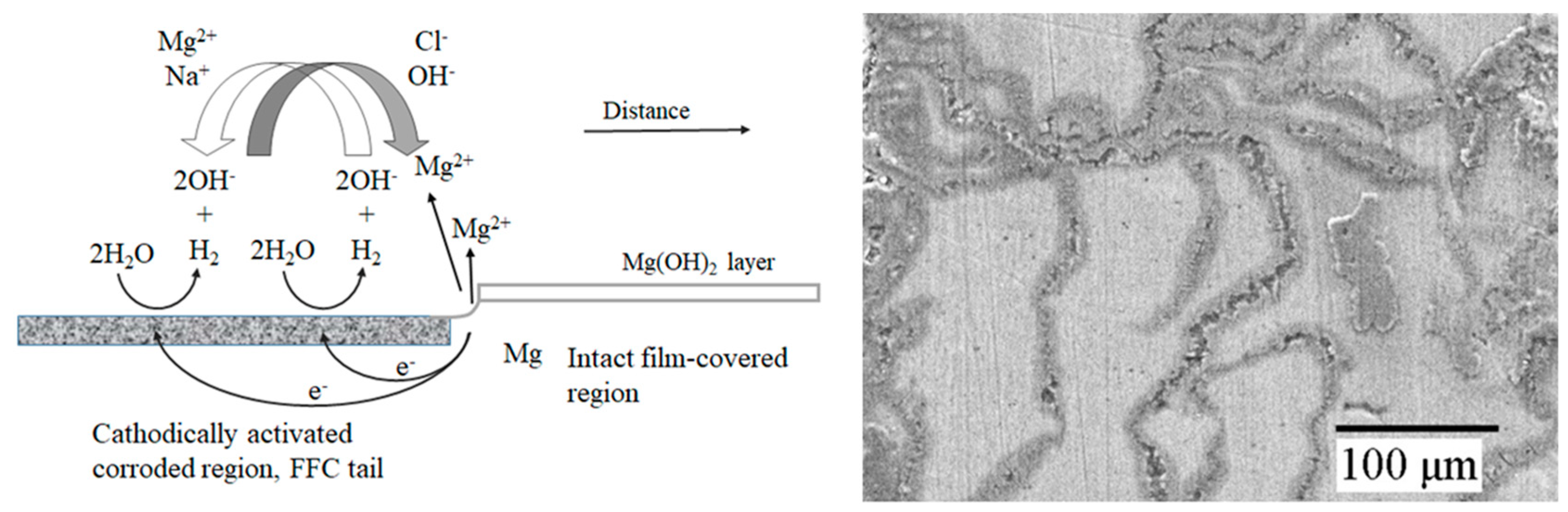
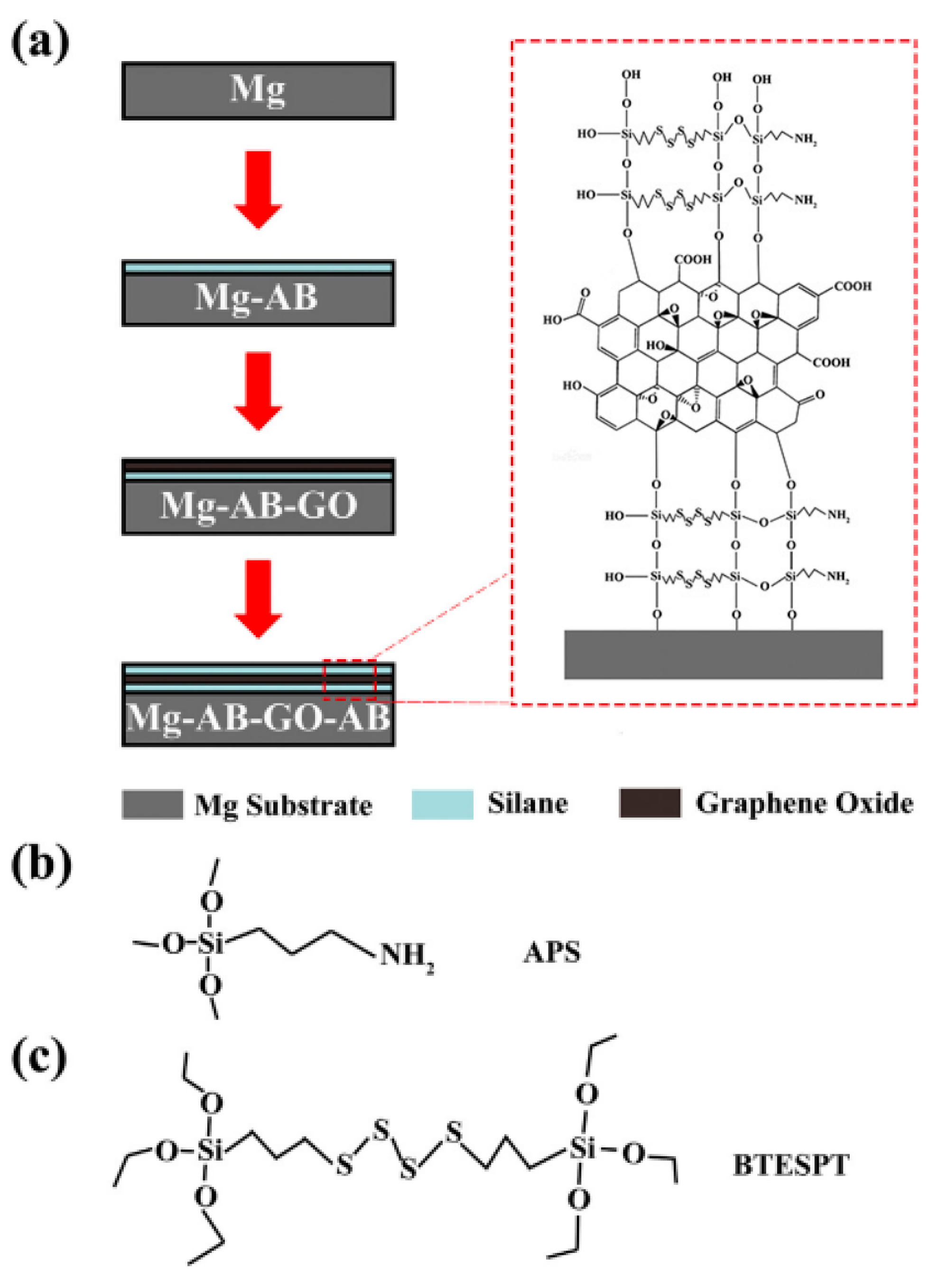
Table 1.
The standard electrode potential of common metal cations.
| Metal Cations | Standard Electrode Potential/V | Metal Cations | Standard Electrode Potential/V |
|---|---|---|---|
| Li+ | −3.02 | Al3+ | −1.71 |
| K+ | −2.92 | Zn2+ | −0.76 |
| Na+ | −2.71 | Fe2+ | −0.44 |
| Ce3+ | −2.48 | Cd2+ | −0.40 |
| Pr3+ | −2.46 | Ni2+ | −0.24 |
| Nd2+ | −2.43 | Sn2+ | −0.14 |
| Y2+ | −2.37 | Cu2+ | 0.34 |
| Mg2+ | −2.37 | Ag+ | 0.8 |
Table 2.
The Ecorr and Icorr of A04, A08, and A12 in 3.5 wt.% NaCl solution [42]. Reprinted with permission from the Chinese Academy of Sciences, Inst Metal Research. Copyright 2023.
Table 2.
The Ecorr and Icorr of A04, A08, and A12 in 3.5 wt.% NaCl solution [42]. Reprinted with permission from the Chinese Academy of Sciences, Inst Metal Research. Copyright 2023.
| Alloys | Ecorr (Vsce) | Icorr (μA/cm2) |
|---|---|---|
| A04 | −1.671 | 885.23 |
| A08 | −1.669 | 316.65 |
| A12 | −1.655 | 212.54 |
Table 3.
The corrosion rate through the immersion test of Mg-x Zn-1.0 Ca alloys [46]. Reprinted with permission from Elsevier. Copyright 2011.
Table 3.
The corrosion rate through the immersion test of Mg-x Zn-1.0 Ca alloys [46]. Reprinted with permission from Elsevier. Copyright 2011.
| Alloy | Vcorr (mm/Year) |
|---|---|
| Pure Mg | 2.08 ± 0.2 |
| Mg-0Zn-1.0Ca | 3.16 ± 0.5 |
| Mg-1.0Zn-1.0Ca | 2.13 ± 0.2 |
| Mg-2.0Zn-1.0Ca | 2.38 ± 0.3 |
| Mg-3.0Zn-1.0Ca | 2.92 ± 0.5 |
| Mg-4.0Zn-1.0Ca | 4.42 ± 1.0 |
| Mg-5.0Zn-1.0Ca | 6.15 ± 1.5 |
| Mg-6.0Zn-1.0Ca | 9.21 ± 1.5 |
Table 4.
Chemical compositions of pure magnesium and magnesium alloys (wt.%) [61]. Reprinted with permission from the Pergamon–Elsevier Science Group. Copyright 2019.
Table 4.
Chemical compositions of pure magnesium and magnesium alloys (wt.%) [61]. Reprinted with permission from the Pergamon–Elsevier Science Group. Copyright 2019.
| Alloy | Al | Mn | Y | Fe | Mg |
|---|---|---|---|---|---|
| P-Mg | 0.001 | 0.001 | 0.003 | 0.0402 | Bal. |
| Mg-3Al | 2.878 | 0.004 | 0.003 | 0.0291 | Bal. |
| Mg-3Al-0.3Mn | 2.598 | 0.253 | 0.003 | 0.0094 | Bal. |
| Mg-3Al-0.05Y | 2.730 | 0.001 | 0.033 | 0.0061 | Bal. |
| Mg-3Al-0.2Y | 2.660 | 0.001 | 0.176 | 0.0051 | Bal. |
| Mg-3Al-0.5Y | 2.900 | 0.001 | 0.548 | 0.0039 | Bal. |
Table 5.
Corrosion potential and corrosion current density of different samples in SBF [102]. Reprinted with permission from Springer. Copyright 2017.
Table 5.
Corrosion potential and corrosion current density of different samples in SBF [102]. Reprinted with permission from Springer. Copyright 2017.
| Samples | Ecorr (V/SCE) | Icorr (μA/cm2) |
|---|---|---|
| Naked | −1.60 | 40.20 |
| PA coating | −1.53 | 35.90 |
| PA-35 wt.% HA | −1.50 | 10.45 |
| PA-45 wt.% HA | −1.41 | 2.28 |
| PA-50 wt.% HA | −1.46 | 26.83 |
Table 6.
EIS data fitting results [102]. Reprinted with permission from Springer. Copyright 2017.
Table 6.
EIS data fitting results [102]. Reprinted with permission from Springer. Copyright 2017.
| Samples | Rs (Ω cm2) | Rt (Ω cm2) | CPE2 (S/cm2/s) | Rp (Ω cm2) | CPE2 (S/cm2/s) |
|---|---|---|---|---|---|
| Naked | 2.2 | 510 | 1.9 × 10⁻⁵ | 635 | 2.2 × 10⁻⁴ |
| PA coating | 2.2 | 1750 | 7.3 × 10⁻⁷ | - | - |
| PA-35 wt.% HA | 2.8 | 3214 | 8.0 × 10⁻⁶ | - | - |
| PA-45 wt.% HA | 2.9 | 5154 | 5.3 × 10⁻⁷ | - | - |
| PA-50 wt.% HA | 2.2 | 1778 | 9.8 × 10⁻⁷ | - | - |
Table 7.
Ecorr and Icorr values of Al films prepared under different sputtering powers in 3.5 wt.% NaCl solution [146]. Reprinted with permission from MDPI. Copyright 2021.
Table 7.
Ecorr and Icorr values of Al films prepared under different sputtering powers in 3.5 wt.% NaCl solution [146]. Reprinted with permission from MDPI. Copyright 2021.
| Sputtering Power/W | Eocp (V) | Ecorr (V/SCE) | Icorr (A/cm2) |
|---|---|---|---|
| Uncoated (AZ31 Substrate) | −1.554 | −1.538 | 1.538 × 10⁻⁵ |
| 50 | −1.548 | −1.602 | 1.269 × 10⁻⁶ |
| 75 | −1.559 | −1.519 | 2.534 × 10⁻⁶ |
| 100 | −1.555 | −1.506 | 4.801 × 10⁻⁶ |
| 150 | −1.561 | −1.357 | 7.033 × 10⁻⁷ |
Table 8.
Advantages and disadvantages of various surface coatings of magnesium alloys.
| Film Forming Method | Advantages | Disadvantages | |
|---|---|---|---|
| Chemical conversion coating | Chromate | Mature process and excellent protection | Cr6+ is toxic, harmful to humans, and pollutes the environment |
| Phosphate | Non-toxic, non-polluting, and low cost | Limited protection as a coating alone, usually applied as a pre-treatment | |
| Molybdate | Green environmental protection and better corrosion resistance | The cost is higher | |
| Stannate | Low cost and low pollution | The corrosion resistance is lower than that of chromate conversion coating, which is used for the pretreatment of composite coating | |
| Phytic acid | Excellent corrosion resistance, non-polluting, and durable coating protection | Fast consumption of treatment solution and the coating quality is easily affected by PH | |
| Rare earth elements | Some coatings show excellent self-healing ability | The loose structure of the membrane layer and bonding with the substrate needs to be strengthened | |
| High-current pulsed electron beam (HCPEB) | Great corrosion resistance, obvious grain refinement, and easy to control the parameters | Requires working under vacuum, which is more costly | |
| Chemical plating | Mature process | Difficulty in recycling chemical plating solutions and short service life | |
| Micro-arc oxidation | The coatings have strong adhesion to the substrate and great protection | High cost and low processing efficiency | |
| Anodic oxidation | The coatings are thick and environmentally friendly | The porous structure of the coatings makes it necessary to carry out post-treatment | |
| Organic coating | Simple operation and economical, with a certain decorative effect | Coatings are prone to deterioration and limited protection | |
| Sol–gel coating | Uniform coatings composition and suitable for complex surfaces | Micropores on the surface, prone to cracking | |
| Magnetron sputtering | Fast deposition, strong bonding, and great densification | High cost and complex process | |
Disclaimer/Publisher’s Note: The statements, opinions and data contained in all publications are solely those of the individual author(s) and contributor(s) and not of MDPI and/or the editor(s). MDPI and/or the editor(s) disclaim responsibility for any injury to people or property resulting from any ideas, methods, instructions or products referred to in the content. |
© 2023 by the authors. Licensee MDPI, Basel, Switzerland. This article is an open access article distributed under the terms and conditions of the Creative Commons Attribution (CC BY) license (https://creativecommons.org/licenses/by/4.0/).
Share and Cite
MDPI and ACS Style
Wu, T.; Zhang, K. Corrosion and Protection of Magnesium Alloys: Recent Advances and Future Perspectives. Coatings 2023, 13, 1533. https://doi.org/10.3390/coatings13091533
AMA Style
Wu T, Zhang K. Corrosion and Protection of Magnesium Alloys: Recent Advances and Future Perspectives. Coatings. 2023; 13(9):1533. https://doi.org/10.3390/coatings13091533
Chicago/Turabian StyleWu, Tao, and Kemin Zhang. 2023. "Corrosion and Protection of Magnesium Alloys: Recent Advances and Future Perspectives" Coatings 13, no. 9: 1533. https://doi.org/10.3390/coatings13091533
Note that from the first issue of 2016, this journal uses article numbers instead of page numbers. See further details here.