Article

Carbon-Supported Fe-Based Catalyst for Thermal-Catalytic CO2 Hydrogenation into C2+ Alcohols: The Effect of Carbon Support Porosity on Catalytic Performance

1
State Key Laboratory of Heavy Oil Processing, College of New Energy, China University of Petroleum (East China), Qingdao 266580, China
2
Shandong Energy Group Co., Ltd., Jinan 250014, China
*
Authors to whom correspondence should be addressed.
Molecules 2024, 29(19), 4628; https://doi.org/10.3390/molecules29194628 (registering DOI)
Submission received: 30 May 2024 / Revised: 24 June 2024 / Accepted: 1 July 2024 / Published: 29 September 2024

Abstract

:
Carbon materials supported Fe-based catalysts possess great potential for the thermal-catalytic hydrogenation of CO2 into valuable chemicals, such as alkenes and oxygenates, due to the excellent active sites’ accessibility, appropriate interaction between the active site and carbon support, as well as the excellent capacities in C-O bond activation and C-C bond coupling. Even though tremendous progress has been made to boost the CO2 hydrogenation performance of carbon-supported Fe-based catalysts, e.g., additives modification, the choice of different carbon materials (graphene or carbon nanotubes), electronic property tailoring, etc., the effect of carbon support porosity on the evolution of Fe-based active sites and the corresponding catalytic performance has been rarely investigated. Herein, a series of porous carbon samples with different porosities are obtained by the K2CO3 activation of petroleum pitch under different temperatures. Fe-based active sites and the alkali promoter Na are anchored on the porous carbon to study the effect of carbon support porosity on the physicochemical properties of Fe-based active sites and CO2 hydrogenation performance. Multiple characterizations clarify that the bigger meso/macro-pores in the carbon support are beneficial for the formation of the Fe5C2 crystal phase for C-C bond coupling, therefore boosting the synthesis of C2+ chemicals, especially C2+ alcohols (C2+OH), while the limited micro-pores are unfavorable for C2+ chemicals synthesis owing to the sluggish crystal phase evolution and reactants’ inaccessibility. We wish our work could enrich the horizon for the rational design of highly efficient carbon-supported Fe-based catalysts.

1. Introduction

The resource utilization of CO2 can alleviate the pressure of the environmental effects of CO2 to a certain extent and, at the same time, provide a new green and sustainable pathway for high value-added chemical synthesis. The conversion of CO2 into valuable chemicals, such as olefins, aromatics, gasoline, and alcohol, through thermocatalytic hydrogenation technology is an efficient means that stands out among various CO2 utilization technologies due to the high conversion efficiency and promising industrial application [1,2,3,4,5,6,7,8,9,10,11,12]. Among these chemicals, C2+ alcohols (C2+OH) have received the attention of many scientists due to their wide range of uses. Most C2+ alcohols, including ethanol with a specific energy of 8.3 kWh/kg and an energy density of 6.7 kWh/L, hold significant economic value and an energy density comparable to gasoline (12.9 kWh/kg and 9.5 kWh/L) [13]. Many countries have used ethanol as a fuel additive or solvent for chemical products. Some C2-C5 alcohols can be used directly as a transportation fuel or blended with gasoline to increase the octane rating, thereby improving engine performance [14]. Furthermore, C2+ alcohols serve as essential raw materials for the production of various products, including plastics, plasticizers, and pharmaceuticals. However, the lack of highly efficient catalysts is still the bottleneck that limits the application of CO2 hydrogenation into C2+OH technology at a large scale.
Significant progress has been made in the study of CO2-to-C2+OH catalysts in recent years, mainly noble metal-based catalysts represented by Rh-based and transition metal-based catalysts represented by Co-, Cu-, and Mo-based. However, such catalysts are suffering from some inherent problems. Although the noble metal catalysts deliver high selectivity for C2+OH, their expensive catalyst costs and low CO2 conversion rates have hindered their industrialization. Transition metal-based catalysts, which are relatively cost-effective, generally suffer from low C2+OH selectivity, and the catalytic stability needs to be further improved [15]. Many scientists are gradually studying Fe-based catalysts because of their simplicity, ease of obtaining, low price, and lack of environmental pollution. However, block Fe-based catalysts undergo significant nanoparticle agglomeration and particle size growth during the reaction process, leading to mechanical decomposition and stability loss [16]. Therefore, Fe-based species are usually immobilized on porous supports to prolong the stability. Due to the strong interaction between the metal and the support, the general silica and alumina supports are prone to irreversibly forming inactive substances during the reaction [17]. Nanostructured carbon materials are desirable for dispersing Fe-based nanoparticles due to the appropriate metal–support interaction, high surface area, tunable texture property, and controlled surface chemistry [18,19,20,21,22]. However, most of the current research is directly loading active metal onto carbon supports [23,24,25,26,27], and there is still a great challenge for the exploration of the domain-limiting effect of pore structure on the reaction properties.
This work loaded the Na-modified Fe-based species onto the carbon supports with different pore structures that were prepared by the K2CO3 activation of petroleum asphalt at different temperatures. The porous carbon support effectively controls the size and distribution of the Fe-based nanoparticles, in which carbon supports with larger meso/macro-pores could facilitate the sufficient penetration of the Fe-based component into the pore structure and improve the dispersion. Furthermore, the support porosity influences the differential adsorption of H2 and CO2 molecules on the catalyst surface, with the CO2-rich and H2-poor environments near the Fe-based species promoting the evolution of the Fe5C2 phase as the active site, thereby enhancing CO2 hydrogenation performance. This result reveals the influence of carbon support porosity on the catalytic performance and provides an important guideline for future in-depth investigations into carbon-supported Fe-based catalysts for thermal-catalytic CO2 hydrogenation.

2. Results and Discussion

2.1. Structural Characterization of Catalysts

Figure 1a illustrates the preparation process of the carbon-supported Fe-based catalysts. Initially, petroleum asphalt underwent pyrolysis via the one-step activation method using K2CO3 at varying temperatures under an N2 atmosphere. The resulting carbon supports were denoted as MCx (x represents the pyrolysis temperature, x = 700/800/900/1000 °C). Subsequently, the Fe-based active sites were loaded onto a carbon support by the impregnation method followed by carbonization treatment at 550 °C for 3 h under an N2 atmosphere and further impregnation with the Na promoter to obtain the catalyst named NaFe/MCx.
The N2 adsorption–desorption test was performed on petroleum asphalt-derived porous carbon MCx to explore the effect of K2CO3 activation temperature on pore structure (Table 1). MC700 and MC1000 delivered the lowest and highest N2 adsorption–desorption capacity, respectively (Figure 1b,c and Table 1). For MC700, the micropores dominated the pore structure with a 926.45 m2 g−1 specific surface area of micropores. The specific surface area of mesopores accounted for only 4% of the total. Obviously, the percentage of mesopores in MCx increased with the increase in pyrolysis temperature. The specific surface area of the mesopores in MC1000 increased to 910.74 m2 g−1, constituting 55% of the total specific surface area. The increasing mesopores’ specific surface area indicated that the pore structure of MCx, especially the mesoporous property, can be modulated by adjusting the pyrolysis temperature. Despite the high surface area of microporous-dominant materials, their CO2 trapping ability and kinetic performance may be unsatisfactory due to the insufficient diffusion of CO2 molecules into the core of micropores [28]. Meso/macro-pores, conversely, possess a larger pore volume, exhibit excellent CO2 trapping capacity under high pressure, facilitate faster mass transfer [29], and provide sufficient sites for anchoring Fe-based active sites, thus enhancing accessibility to catalytically active sites [30].
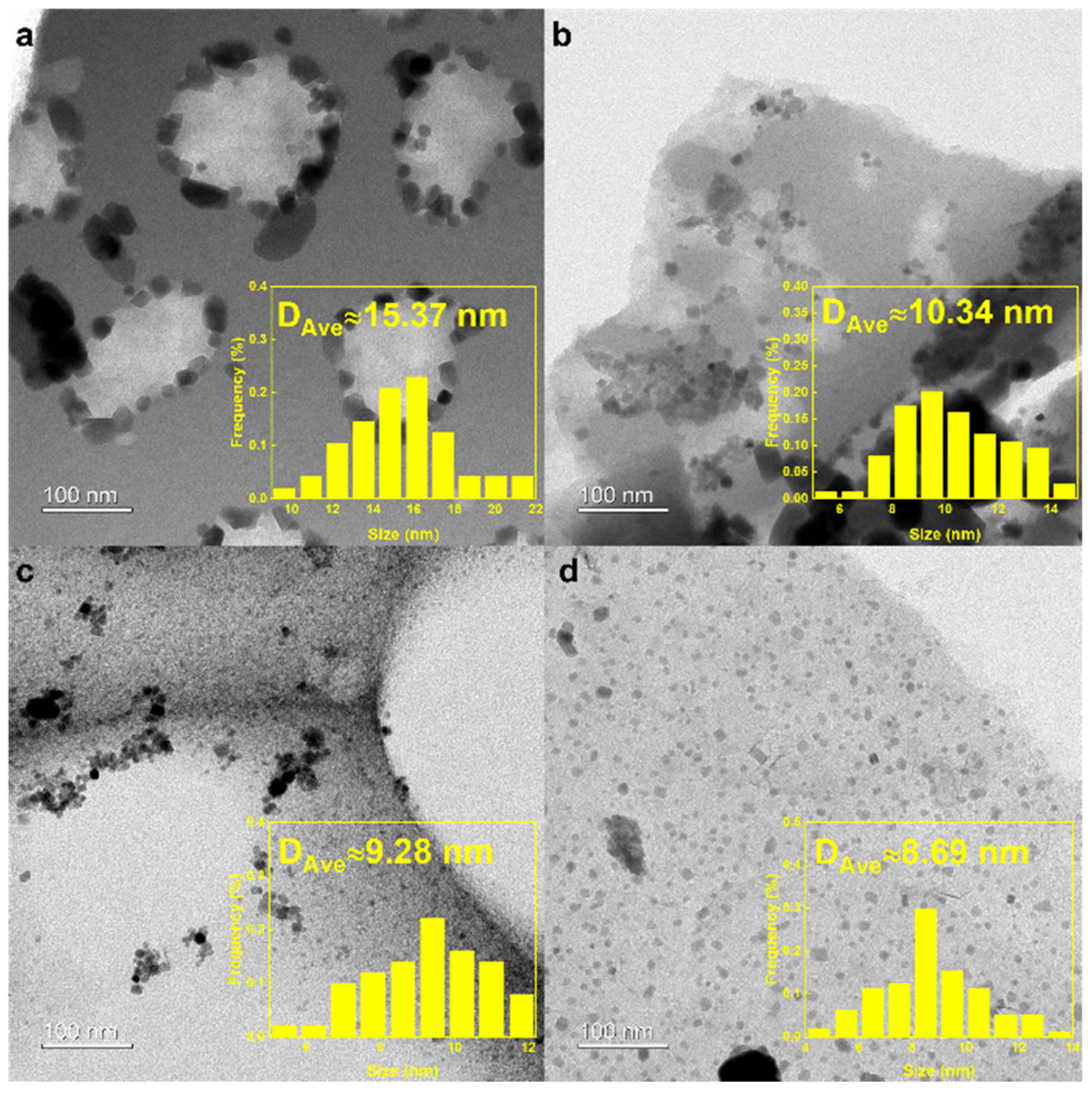
Transmission electron microscope (TEM) characterization was performed on the fresh NaFe/MCx catalysts to observe the distribution of Fe-based particles on the carbon support (Figure 2). Based on the findings from Figure 1 and Table 1, the specific surface area of the MC700 catalyst was the smallest, with micropores dominating the pore structure. This prevents most of the Fe-based particles from entering the pores of the carbon support, resulting in large particle sizes accumulated outside the carbon support with the largest average diameter of 15.37 nm (Figure 2a). With the pyrolysis temperature increased, the average pore size of the carbon support was enlarged. Therefore, the Fe-based nanoparticles were more easily dispersed into the pore structure, causing the reduced average diameter of the Fe-based active sites (Figure 2b,c). A TEM image of NaFe/MC1000 revealed uniformly dispersed Fe-based nanoparticles without an apparent accumulation on the carbon support. The Fe-based nanoparticles with an average diameter of 8.69 nm were well dispersed on the carbon supports and encapsulated in the pores of MC1000 (Figure 2d). The uniform distribution of Fe-based active sites inside the pores of carbon supports could enhance the provision of catalytic active centers that are easily accessible to gaseous reactants, thus improving the catalytic performance of thermal-catalytic CO2 hydrogenation.
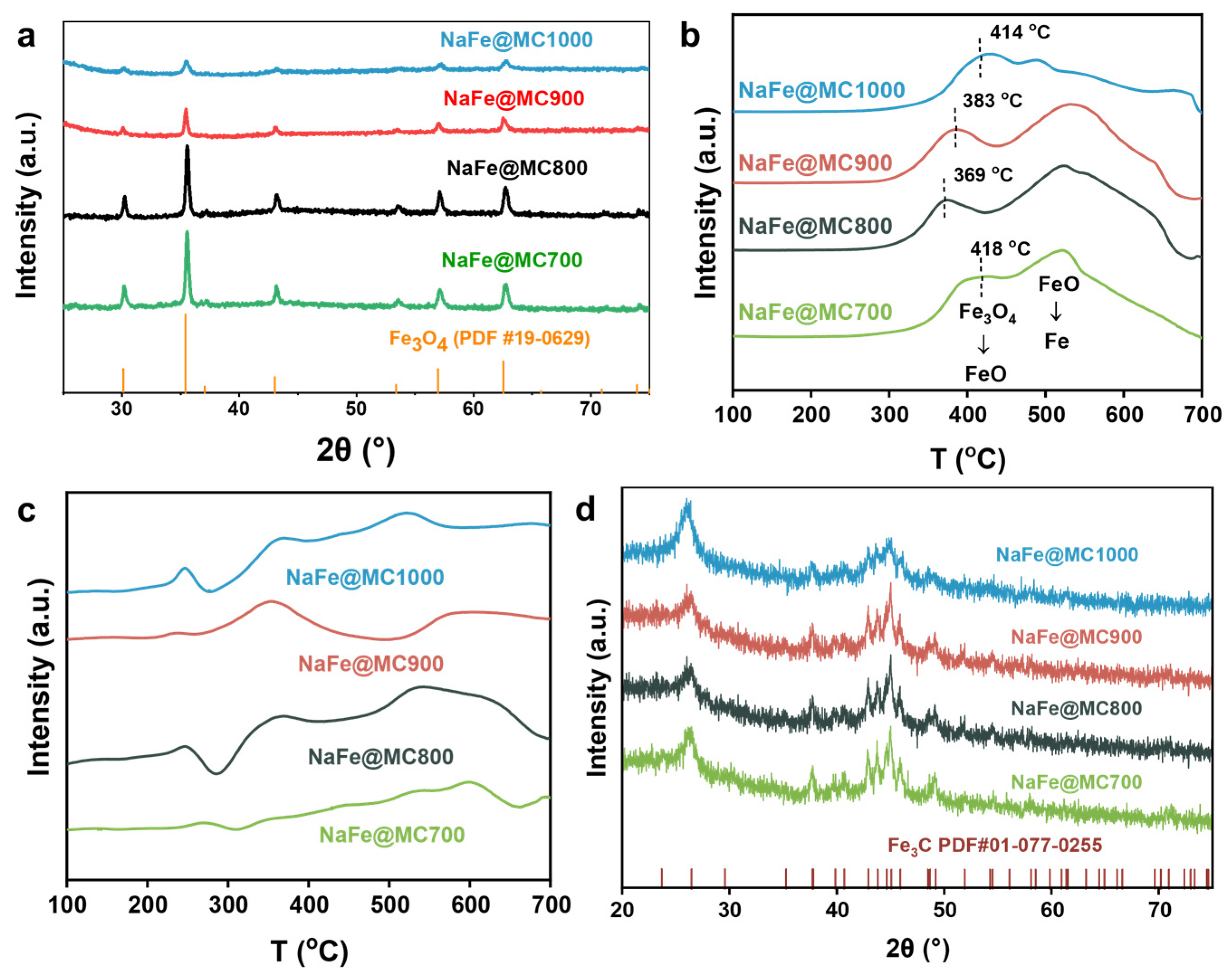
X-ray diffraction (XRD) characterization elucidated the crystal phase of NaFe/MCx catalysts (Figure 3a). The fresh NaFe/MCx catalyst was primarily composed of the Fe3O4 phase. With the increase in the activation temperature, the dispersion of the Fe-based component increased, accompanied by a decrease in Fe3O4 diffraction peak intensity, which is consistent with the TEM characterization results. Fe3O4 is the main active site of the reverse water–gas shift (RWGS, CO2 + H2 → CO + H2O) reaction, which dissociates CO2 into CO for the subsequent Fischer–Tropsch synthesis [31]. As the reaction proceeds, Fe sites undergo gradual carburization, transforming from Fe3O4 to Fe-based carbide phases. H2-temperature programmed reduction (H2-TPR) recorded the reduction behavior of the catalysts. As shown in Figure 3b, the H2-TPR curves showed the multi-step reduction processes of Fe3O4 in catalysts [32,33]. The exposure degree of Fe-based active sites under the reducing atmosphere determines the reduction behavior of the catalyst. Benefitting from the smallest particle size, highest intra-pore dispersion, and substantial pore volume, NaFe/MC1000 exhibited superior reduction behavior among all samples, with a slight shift in the reduction peak towards lower temperatures. Conversely, larger Fe-based nanoparticles entering the pore structure diminished Fe-based active sites’ ability to contact H2, resulting in a wider reduction process of NaFe/MC900 and NaFe/MC800. The largest catalyst particle size of NaFe/MC700 hindered the reduction behavior but primarily stacked outside pore structures, maintaining relatively strong H2 contact, hence exhibiting a significantly shorter reduction interval [34,35,36].
Figure 3c,d represent the CO-temperature programmed reduction (CO-TPR) profiles of the NaFe/MCx catalysts and the XRD patterns of the catalysts after CO-TPR, respectively. The peaks that appeared in the CO-TPR curves represented the consumption of CO, indicating that CO can reduce the Fe-based nanoparticles for carburization and form Fe-based carbide compounds during the CO-TPR process. The appearance of Fe3C-related peaks in the XRD patterns of the CO-TPR catalysts also confirmed this conclusion. Notably, the NaFe/MC1000 catalyst delivered the lowest CO-TPR temperature, implying that the smallest Fe-based nanoparticles endowed by the mesoporous carbon support were easier to be reduced and carbonized by CO molecules. However, for the NaFe/MC700 catalyst, no obvious CO-TPR peaks were detected due to the difficulty of the reduction and carbonization of the largest Fe-based nanoparticles that stacked outside the micropores.

2.2. Catalytic Performance

The Fe-based component served as the active site, facilitating the dissociation of CO2, carbon chain growth, and the insertion of oxygen-containing intermediates. Consequently, the Na/MC1000 sample was inactive due to the absence of these crucial sites (Table 2). Na acts as a promoter, increasing the surface basicity of Fe catalysts, facilitating the formation of iron carbide phases, and inhibiting the over-hydrogenation process by strengthening the desorption of desirable products (especially alkenes) [37,38,39]. As a result, Fe/MC1000 catalysts without Na doping exhibited lower C2+ alcohols selectivity and higher selectivity of CH4 and paraffins (Table 2). Although the contents of Fe and Na were consistent among different catalysts, they showed completely different catalytic performance, as shown in Table 2 and Figure 4. NaFe/MC700 exhibited a CO2 conversion of 6.1% and the highest CH4 selectivity of 90.9%, devoid of valuable oxygenates in the product. As the pyrolysis temperature of the carbon support increased, the CO2 conversion rate and C2+OH selectivity gradually rose, while CH4 selectivity declined. NaFe/MC1000 exhibited the highest CO2 conversion (22.8%) and selectivity towards C2+OH (22.6%), alongside the lowest CH4 selectivity (22.5%). Furthermore, over a 48 h testing period, the CO2 conversion and product distribution of NaFe/MC1000 remained stable without being impacted by carbon deposition or pore blockage (Table 2 and Figure 4c,d). We believe that the pore structure of the catalysts endowed by different pyrolysis temperatures plays a decisive role in the reaction performance, and the increased proportion of the mesopores in the catalysts will improve the conversion of CO2 and the selectivity of C2+OH.
Figure 4b exhibits the trend of the CO2 conversion rate of NaFe/MCx. The observed gradual increase in CO2 conversion over time can be attributed to the induction period required by the Fe-based catalyst to achieve a stable active state (Figure 4b). This process involves the remodeling of the catalyst surface, during which the Fe-based catalyst undergoes carburization during the reaction and gradually forms surface active sites represented by Fe3O4 and Fe5C2 to adsorb and activate CO2 molecules [40]. The CO2 conversion rate of NaFe/MC700 markedly declined after 6 h of reaction initiation. The CO2 conversion rate of NaFe/MC700 markedly declined after 6 h of reaction initiation. This trend can be attributed to the predominantly microporous structure of NaFe/MC700. The microporous structure limits the accessibility and evolution of the Fe-based active sites, resulting in suboptimal catalytic performance. Additionally, catalysts with a primarily microporous structure are more prone to significant deactivation due to the serious carbon deposition phenomenon [41].

2.3. Influence of Catalyst Pore Structure on Catalytic Performance

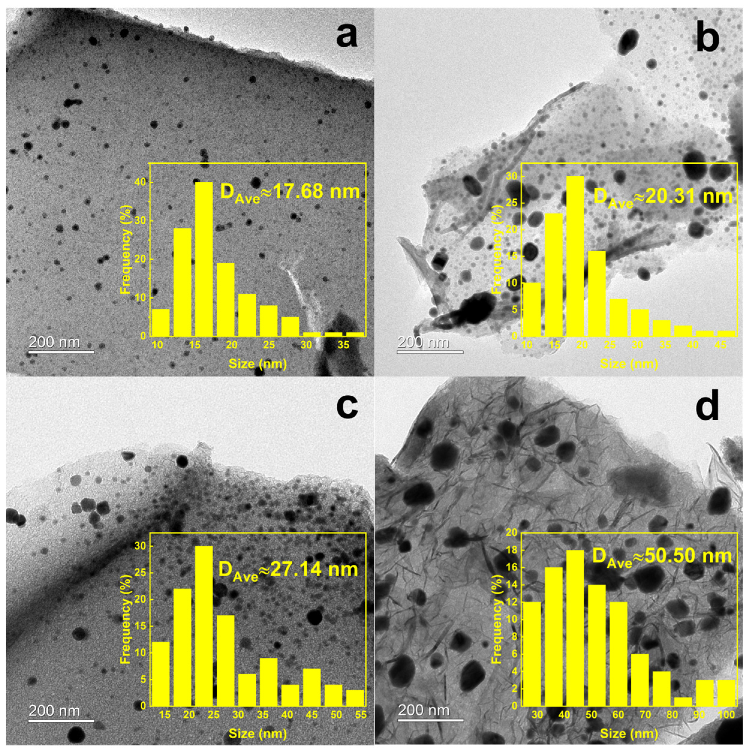
Figure 5 reflects the morphology of Fe-based particles in the spent NaFe/MCx catalysts. The TEM images revealed no significant aggregation of Fe-based particles on the carbon supports, indicating that the proper interaction between carbon supports and metal particles effectively prevents agglomeration during the reaction. The particle sizes increased to varying degrees after the CO2 hydrogenation reaction, indicating distinct evolution patterns of Fe species driven by different pore-structured supports. Specifically, for NaFe/MC1000 catalysts (Figure 5d), the prevalence of mesopores promotes significant Fe species evolution during reaction, as evidenced by the obvious growth of Fe-based particle size.
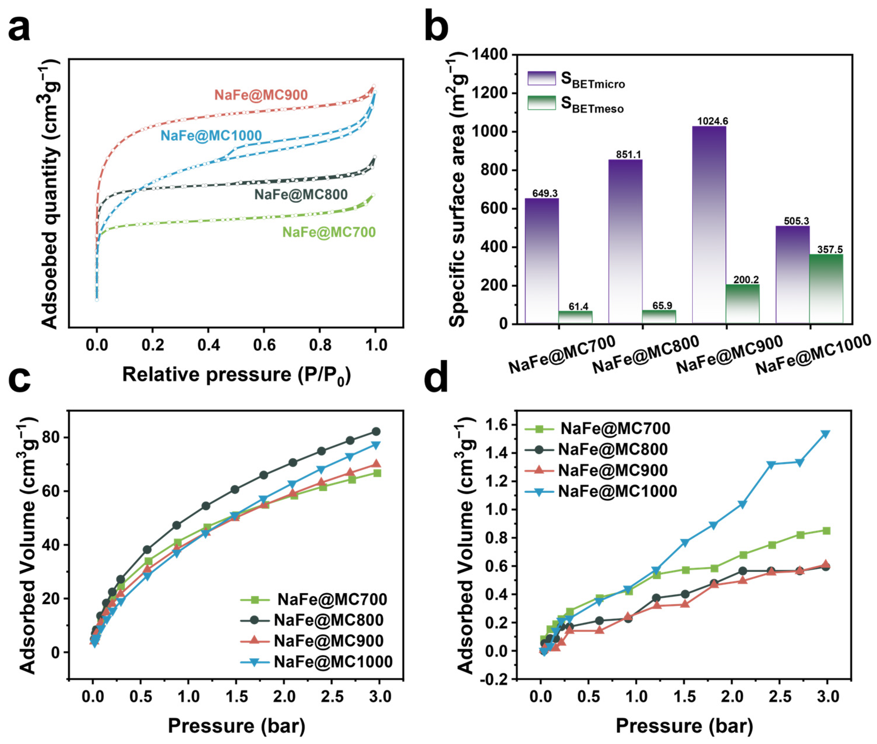
N2 adsorption–desorption tests were conducted on fresh catalysts to explore the pore structure of the NaFe/MCx catalysts (Figure 6a,b). NaFe/MC700 and NaFe/MC900 exhibited the lowest and highest N2 adsorption–desorption capacities, respectively. NaFe/MC700 had the lowest specific surface area of 710.77 m2 g−1, with micropores dominating the pore structure. The specific surface area of NaFe/MCx was gradually increased with the increase in the activation temperature, but exhibited a reduction when carbon support pyrolysis reached 1000 °C. This reduction could be attributed to the graphitic carbon layer formation in the NaFe/MC1000 catalyst as the activation temperature reached 1000 °C. Additionally, the adsorption hysteresis loop appeared in the N2 adsorption–desorption curve of the NaFe/MC1000 (Figure 6a), which indicates that the pores retained after pyrolysis are mainly mesoporous [41]. Notably, the mesoporous specific surface area of NaFe/MC1000 reached the highest value of 357.49 m2 g−1 (Table 3 and Figure 6b). The changes in the pore structure of the carbon support during pyrolysis were related to the activation of K2CO3. During the chemical activation process, a higher activation temperature intensified the K2CO3 activation effect, enhancing etching and pore creation in carbon material [42].
The adsorption capacity of carbon-supported Fe-based catalysts to the feedstock gas components (CO2 and H2) significantly influences their reaction performance. Accordingly, physical adsorption–desorption tests for CO2 and H2 were conducted. The results indicated that the adsorption capacities for both CO2 and H2 increased with the pressure rising to 3 bar (Figure 6c,d). Notably, the CO2 adsorption capacity consistently surpassed that for H2, attributable to the inherent properties of Fe-based catalysts. Incorporating transition metal oxides like Cu and Ni into the carbon support enhances CO2 adsorption capability [43,44,45,46]. Similarly, Fe-based species on the carbon support also enhance CO2 adsorption capability significantly. NaFe/MC700 exhibited the lowest CO2 adsorption capacity, while its adsorption capacity for H2 was higher (Figure 6c,d). H2 is more readily diffused into the micropore-dominated structure of NaFe/MC700, creating an H2-rich environment near the active sites during reaction and leading to the over-hydrogenation phenomenon. This behavior corresponds well with the high CH4 selectivity observed in NaFe/MC700 (Table 2). Conversely, the mesoporous NaFe/MC1000 catalyst demonstrated the highest H2 physisorption and substantial CO2 physisorption, and the larger meso/macro pores in the carbon support facilitated the effective diffusion of both gases, matching the rates of CO2 activation and hydrogenation to boost the reaction performance (Figure 6c,d). Consequently, the CH4 selectivity was reduced, and the selectivity for C2+OH increased to 22.6% (Table 2), underscoring the role of an enhanced mesoporous structure in promoting the formation of C2+OH.
The temperature-programmed desorption mass spectrometry (TPD-MS) of CO2/H2 was conducted on NaFe/MCx catalysts to examine the chemisorption behavior of the feed gas components. As the pyrolysis temperature increased, the position of the CO2 desorption peak shifted toward lower temperatures (Figure 7a), with the NaFe@MC1000 catalyst exhibiting the lowest CO2 desorption temperature due to the higher mesopore content. The H2 desorption peak for the NaFe/MC700 catalyst shifted to higher temperatures and intensified (Figure 7b), indicating strong H2 adsorption on the catalyst surface, likely facilitating H2-rich environments conducive to the over-hydrogenation of -CO* intermediates and predominant production of CH4 (Table 2). As the pyrolysis temperature increased, the catalyst’s H2 adsorption capacity decreased, establishing a catalytic interface with moderate hydrogenation potential that effectively suppressed undesirable hydrogenation reactions and enhanced carburization effects.
Figure 7c,d show the XRD and X-ray Photoelectron Spectroscopy (XPS) profiles of the spent NaFe/MCx catalysts. For the spent catalysts, Fe3O4 was the mainly oxide phase, while Fe3C and Fe5C2 were mainly the Fe-based carbide phases. The XPS characterization of the spent NaFe/MCx catalysts revealed the formation of Fe-C bonds in all catalysts, indicating the presence of Fe-based carbide compounds, consistent with the XRD results. There was almost no formation of the Fe-based carbide phase in the predominantly microporous NaFe/MC700 catalyst, and the signals of the Fe-based carbide phase in the spent catalysts became more pronounced with the increase in mesopores. As is known, the active phases of Fe3O4 and Fe-based carbide make outstanding contributions to the thermal-catalytic CO2 hydrogenation reaction, in which CO2 molecules are converted to -CO* intermediates by the Fe3O4 active site via the RWGS reaction. Subsequently, -CO* carburizes the Fe3O4 active phase to carbides dominated by the Fe3C and Fe5C2 phases with H2-assisted action [47,48], while the Fe-based carbides dissociate or non-dissociatively activate the -CO* intermediates to -CHx* or -CHyO* (x = 1, 2, or 3, and y = 0, 1, or 2), respectively, and further C-C coupling with subsequent hydrogenation steps occur to finalize the synthesis of C2+OH [3,49].

3. Materials and Methods

3.1. Materials

Petroleum asphalt was supplied by the Sinopec Jiu Jiang Company (Jiu Jiang, China). Potassium carbonate (K2CO3, AR) and sodium carbonate (Na2CO3, AR) were obtained from Sinopharm Chemical Reagent Co., Ltd (Shanghai, China). Ferric nitrate nonahydrate (Fe(NO3)3·9H2O, AR) was purchased from Shanghai Macklin Biochemical Co., Ltd. (Shanghai, China). All reagents were used directly without further purification.

3.2. Catalyst Preparation

The carbon supports were prepared by a one-step heat-treatment method using K2CO3 chemical activation. First, 1 g of petroleum asphalt and 4 g of K2CO3 were ground and mixed thoroughly, then heated up to 700/800/900/1000 °C for 2 h in a tube furnace under an N2 atmosphere at a heating rate of 5 °C·min−1 to obtain the black samples. Subsequently, the samples were washed with deionized water for 12 h at 70 °C and filtered three times to remove unreacted salts, ensuring that no other elements in the catalyst interfered with the experiments. Then, the samples were dried in an oven at 60 °C for 12 h to obtain carbon supports named MC700/800/900/1000, respectively. In the next step, the carbon supports were impregnated with a 15% Fe(NO3)3.9H2O solution, dried at 70 °C for 12 h, and then pyrolyzed at 550 °C under an N2 atmosphere for 3 h. The Na-modified carbon-supported Fe-based catalysts, named NaFe/MCx (x represents the temperature of the calcination, x = 700/800/900/1000), were then fabricated by the impregnation method under the conditions of 3% Na2CO3, a 70 °C thermal treatment, and a 12 h reaction time. Finally, all catalysts were pressed, crushed, and sieved to 20–40 meshes for the CO2 hydrogenation catalytic performance test.

3.3. Catalyst Characterization

The X-ray diffraction (XRD) patterns of the catalysts’ powder were characterized with a Rigaku RINT 2400 X-ray diffractometer using Cu K α-radiation. Transmission electron microscopy (TEM, JEM-2100UHR, JEOL) was used to observe the morphologies of the catalysts before and after the reaction. The crystal phase structures found in the experiments were determined using the PDF–4+ (2019) crystal database and then matched using Highscore Plus software. X-ray photoelectron spectroscopy (XPS, ThermoFisher (Beijing, China), ESCALAB 250Xi) analysis of the reacted catalysts was recorded to determine the elemental composition and valence changes. The specific surface areas and pore size distributions of the catalysts were measured by a Micromeritics 3Flex 2 M P instrument. Before the measurements, the catalysts were degassed at 200 °C for 6 h. The element content of NaFe/MCx catalysts was determined by an inductively coupled plasma optical emission spectrometry (ICP-OES, Agilent ICP-720ES). The specific surface area was calculated by the Brunauer–Emmett–Teller (BET) method. The average pore size and pore volume were calculated using the Barrett–Joyner–Halenda (BJH) method. The pore size distribution was analyzed by the BJH (mesopores) and Horváth–Kawazoe (HK, micropores) methods.
At different temperatures and pressures, the gas adsorption isotherms for CO2 and H2 were determined using the volumetric method on a high-pressure gas adsorption apparatus (BSD-PH, BeiShiDe Instrument Co., Ltd., Beijing, China). The procedure involved loading approximately 0.1 g of the powder sample into the sample tube. Before initiating the gas adsorption test, the sample was placed in a heating furnace, warmed to 200 °C, and activated under vacuum conditions for 5 h. During the adsorption test, the adsorption temperature was precisely controlled using a program-controlled water bath jacket. Various pressure set points were maintained through computer program-controlled procedures.
CO/H2 temperature-programmed reduction (CO/H2-TPR) and CO2/H2-temperature-programmed desorption and mass spectra (CO2/H2-TPD-MS) were performed on a PCA-1200 instrument connected to an MS-200 mass spectrometer (Beijing Builder, Beijing, China). For CO2/H2-TPD, a 30 mg catalyst was pretreated at 150 °C for 30 min under a flow of pure Ar to remove the physically adsorbed water and organic products on the spent catalyst. Then, the sample was saturated with CO2/H2 at 50 °C for 1 h. After removing the physically adsorbed CO2/H2 by a He flow, the CO2/H2-TPD curve was collected under the He flow (30 mL min−1) with a heating rate of 10 °C min−1. The signals of the desorbed H2 (m/z = 2) and CO2 (m/z = 44) were detected by MS and a thermal conductivity detector (TCD). CO/H2-TPR was carried out in a stream of 10% CO/H2 in Ar with a heating rate of 10 °C min−1.

3.4. Catalytic Evaluation

The catalytic activity tests were performed on a continuous flow type fixed-bed reactor with an inner diameter of 6 mm. For the catalytic performance tests, 0.1 g of NaFe/MC700/800/900/1000 catalysts and 1 g of quartz sand were fixed in the middle of the reactor by quartz wool, with 2 g of quartz sand used as a spoiler above the catalyst bed. Before the reaction, the catalyst was reduced by pure H2 at 400 °C for 4 h. After cooling to room temperature, the reactant gas (23.75% CO2, 71.23% H2, and 5.02% Ar) was fed into the reactor until the pressure reached 5 MPa. At the same time, the temperature of the reactor was increased to 320 °C. The heavy hydrocarbons were collected by the ice trap set between the reactor and the back pressure valve, and then analyzed by an off-line gas chromatograph (GC9790II) equipped with an FID and an InerCap-5 capillary column (GL Sciences (Shanghai, China), 0.25 mm × 30 m). The exhaust gas was analyzed by two on-line gas chromatographs (Fuli 9790II, Zhejiang Fuli Analytical Instruments Co., Ltd., Taizhou, China), in which one was equipped with a TCD detector and an active charcoal column for the analysis of Ar, CO, CH4, and CO2, and the other was equipped with an FID detector and a Porapak-Q column for the analysis of light hydrocarbons. CO2 or CO (denoted as COx, x = 1 or 2) conversion and product selectivity were calculated using the following equations.
(1) CO2 conversion was calculated according to the following:
C O 2   C o n v e r s i o n = C O 2 i n l e t C O 2 o u t l e t C O 2 i n l e t × 100 %
where C O 2 i n l e t and C O 2 o u t l e t represent the moles of CO2 at the inlet and outlet, respectively.
(2) Product selectivity, the percentage of CO2 converted into a given product, was calculated as follows:
S e l i = N i × n i 1 i ( N i × n i ) × 100 %
where N i and n i represent the mole percentage and carbon number of product i.
(3) CO selectivity (CO selectivity for CO2 hydrogenation) was calculated according to the following:
C O   s e l e c t i v i t y = C O o u t l e t C O 2 i n l e t C O 2 o u t l e t × 100 %
The carbon balances of the reaction data were calculated, and all were higher than 90%. Typically, the experimental data after the reaction of 24 h were used for discussion.

4. Conclusions

Porous carbon support Na-modified Fe-based catalysts were prepared by K2CO3 activation combined with the impregnation method using cheap and readily available petroleum asphalt as a carbon source. The fabricated catalysts were applied in the CO2 hydrogenation reaction to obtain high value-added C2+OH chemicals. Varying the activation temperature of petroleum asphalt obtained NaFe/MCx catalysts with different pore structures. The NaFe/MC1000 catalyst with the highest percentage of mesopores showed the most excellent catalytic activity. Under the reaction conditions of 320 °C, 5 MPa, and GHSV = 9000 mL gcat−1 h−1, the CO2 conversion was 22.8%, and the C2+ alcohol selectivity was 22.6%. The characterization results showed that the pore-limiting role of carbon support influenced the size and distribution of Fe-based nanoparticles and the adsorption pattern of reactive gases, which in turn affects the formation of the Fe5C2 active phase by carburization and, ultimately, the performance of CO2 hydrogenation. The catalysts with a larger mesoporous specific surface area exhibited higher CO2 conversion and C2+OH selectivity due to the preferential formation of the Fe5C2 crystalline phase for C-C coupling. We wish our work could provide guidance for the rational design of the carbon-supported Fe-based catalyst for CO2 hydrogenation into C2+OH.

Author Contributions

Conceptualization, Y.C. and Y.W.; methodology, Y.C. and L.J.; validation, Y.C., P.D. and X.F.; formal analysis, Y.C., L.J., S.L. and Q.L.; investigation, Y.C. and S.L.; resources, Y.W. and M.W.; writing—original draft preparation, Y.C.; writing—review and editing, Y.W. and M.W. visualization, Y.C., L.J., P.D. and X.F.; supervision, Y.W. and M.W.; project administration, Y.W. and M.W. All authors have read and agreed to the published version of the manuscript.

Funding

This research was funded by the National Key Research and Development Program of China (2023YFB4104500, 2023YFB4104502), the National Natural Science Foundation of China (22108310), the Science and Technology Innovation Project of the Shandong Energy Group Co., Ltd. (SNKJ2023A03), and the funding from the Key Laboratory for Green Chemical Technology of Ministry of Education.

Institutional Review Board Statement

Not applicable.

Informed Consent Statement

Not applicable.

Data Availability Statement

The raw data supporting the conclusions of this article will be made available by the authors on request.

Conflicts of Interest

Author Xiaoli Fu and Qiang Liu were employed by the company Shandong Energy Group Co., Ltd. The remaining authors declare that the research was conducted in the absence of any commercial or financial relationships that could be construed as a potential conflict of interest.

References

  1. Gao, P.; Li, S.; Bu, X.; Dang, S.; Liu, Z.; Wang, H.; Zhong, L.; Qiu, M.; Yang, C.; Cai, J.; et al. Direct conversion of CO2 into liquid fuels with high selectivity over a bifunctional catalyst. Nat. Chem. 2017, 9, 1019–1024. [Google Scholar] [CrossRef] [PubMed]
  2. Li, Z.; Wang, J.; Qu, Y.; Liu, H.; Tang, C.; Miao, S.; Feng, Z.; An, H.; Li, C. Highly selective conversion of carbon dioxide to lower olefins. ACS Catal. 2017, 7, 8544–8548. [Google Scholar] [CrossRef]
  3. Wei, J.; Ge, Q.; Yao, R.; Wen, Z.; Fang, C.; Guo, L.; Xu, H.; Sun, J. Directly converting CO2 into a gasoline fuel. Nat. Commun. 2017, 8, 15174. [Google Scholar] [CrossRef] [PubMed]
  4. Liu, X.; Wang, M.; Zhou, C.; Zhou, W.; Cheng, K.; Kang, J.; Zhang, Q.; Deng, W.; Wang, Y. Selective transformation of carbon dioxide into lower olefins with a bifunctional catalyst composed of ZnGa2O4 and SAPO-34. Chem. Commun. 2018, 54, 140–143. [Google Scholar] [CrossRef]
  5. Ni, Y.; Chen, Z.; Fu, Y.; Liu, Y.; Zhu, W.; Liu, Z. Selective conversion of CO2 and H2 into aromatics. Nat. Commun. 2018, 9, 3457. [Google Scholar] [CrossRef]
  6. Wei, J.; Yao, R.; Ge, Q.; Wen, Z.; Ji, X.; Fang, C.; Zhang, J.; Xu, H.; Sun, J. Catalytic hydrogenation of CO2 to isoparaffins over Fe-based multifunctional catalysts. ACS Catal. 2018, 8, 9958–9967. [Google Scholar] [CrossRef]
  7. Li, Z.; Qu, Y.; Wang, J.; Liu, H.; Li, M.; Miao, S.; Li, C. Highly selective conversion of carbon dioxide to aromatics over tandem catalysts. Joule 2019, 3, 570–583. [Google Scholar] [CrossRef]
  8. Cui, X.; Gao, P.; Li, S.; Yang, C.; Liu, Z.; Wang, H.; Zhong, L.; Sun, Y. Selective production of aromatics directly from carbon dioxide hydrogenation. ACS Catal. 2019, 9, 3866–3876. [Google Scholar] [CrossRef]
  9. Li, K.; Chen, J.G. CO2 hydrogenation to methanol over ZrO2-containing catalysts: Insights into ZrO2 induced synergy. ACS Catal. 2019, 9, 7840–7861. [Google Scholar] [CrossRef]
  10. Jiang, X.; Nie, X.; Guo, X.; Song, C.; Chen, J.G. Recent advances in carbon dioxide hydrogenation to methanol via heterogeneous catalysis. Chem. Rev. 2020, 120, 7984–8034. [Google Scholar] [CrossRef]
  11. Wang, Y.; Sun, J.; Noritatsu, T. Clever nanomaterials fabrication techniques encounter sustainable C1 catalysis. Acc. Chem. Res. 2023, 56, 2341–2353. [Google Scholar] [CrossRef] [PubMed]
  12. Wang, W.; Zeng, C.; Noritatsu, T. Recent advancements and perspectives of the CO2 hydrogenation reaction. Green Carbon 2023, 1, 133–145. [Google Scholar] [CrossRef]
  13. Shyama, C.M.; Amitabha, D.; Diptendu, R.; Sandeep, D.; Akhil, S.N.; Long, C.; Biswarup, P. Developments of the heterogeneous and homogeneous CO2 hydrogenation to value-added C2+-based hydrocarbons and oxygenated products. Coord. Chem. Rev. 2022, 471, 214737. [Google Scholar]
  14. Ho, T.L.; Cecilia, M.; Daniel, C.F.; Joseph, A.S.; Javier, P.R. Status and prospects in higher alcohols synthesis from syngas. Chem. Soc. Rev. 2017, 46, 1358. [Google Scholar]
  15. Xu, D.; Wang, Y.; Ding, M.; Hong, X.; Liu, G.; Tsang, S.C.E. Advances in higher alcohol synthesis from CO2 hydrogenation. Chem 2021, 7, 849–881. [Google Scholar] [CrossRef]
  16. Torres Galvis, H.M.; de Jong, K.P. Catalysts for production of lower olefins from synthesis gas: A review. ACS Catal. 2013, 3, 2130–2149. [Google Scholar] [CrossRef]
  17. Hirsa, M.T.G.; Johannes, H.B.; Krijn, P.J. Supported iron nanoparticles as catalysts for sustainable production of lower olefins. Science 2012, 335, 835–838. [Google Scholar]
  18. Francisco, R.R. The role of carbon materials in heterogeneous catalysis. Pergamon 1998, 36, 159–175. [Google Scholar]
  19. Xiong, H.; Jewell, L.L.; Coville, N.J. Shaped carbons as supports for the catalytic conversion of syngas to clean fuels. ACS Catal. 2015, 5, 2640–2658. [Google Scholar] [CrossRef]
  20. Cheng, Y.; Lin, J.; Xu, K.; Wang, H.; Yao, X.; Pei, Y.; Yan, S.; Qiao, M.; Zong, B. Fischer–Tropsch synthesis to lower olefins over potassium-promoted reduced graphene oxide supported iron catalysts. ACS Catal. 2015, 6, 389–399. [Google Scholar] [CrossRef]
  21. Santos, V.P.; Wezendonk, T.A.; Jaén, J.J.D.; Dugulan, A.I.; Nasalevich, M.A.; Islam, H.-U.; Chojecki, A.; Sartipi, S.; Sun, X.; Hakeem, A.A.; et al. Metal organic framework-mediated synthesis of highly active and stable Fischer-Tropsch catalysts. Nat. Commun. 2015, 6, 6451. [Google Scholar] [CrossRef]
  22. Wezendonk, T.A.; Santos, V.P.; Nasalevich, M.A.; Warringa, Q.S.E.; Dugulan, A.I.; Chojecki, A.; Koeken, A.C.J.; Ruitenbeek, M.; Meima, G.; Islam, H.-U.; et al. Elucidating the nature of Fe species during pyrolysis of the Fe-BTC MOF into highly active and stable Fischer–Tropsch catalysts. ACS Catal. 2016, 6, 3236–3247. [Google Scholar] [CrossRef]
  23. Ma, W.; Ding, Y.; Lin, L. Fischer-Tropsch synthesis over activated-carbon-supported cobalt catalysts: Effect of Co loading and promoters on catalyst performance. Ind. Eng. Chem. Res. 2004, 43, 2391–2398. [Google Scholar] [CrossRef]
  24. Wang, T.; Ding, Y.; Xiong, J.; Yan, L.; Zhu, H.; Lu, Y.; Lin, L. Effect of vanadium promotion on activated carbon-supported cobalt catalysts in Fischer–Tropsch synthesis. Catal. Lett. 2006, 107, 47–52. [Google Scholar] [CrossRef]
  25. Du, H.; Zhu, H.; Liu, T.; Zhao, Z.; Chen, X.; Dong, W.; Lu, W.; Luo, W.; Ding, Y. Higher alcohols synthesis via CO hydrogenation on Fe-promoted Co/AC catalysts. Catal. Today 2017, 281, 549–558. [Google Scholar] [CrossRef]
  26. Oschatz, M.; Krans, N.; Xie, J.; de Jong, K.P. Systematic variation of the sodium/sulfur promoter content on carbon-supported iron catalysts for the Fischer–Tropsch to olefins reaction. J. Energy Chem. 2016, 25, 985–993. [Google Scholar] [CrossRef]
  27. Chen, Y.; Ma, L.; Zhang, R.; Ye, R.; Liu, W.; Wei, J.; Ordomsky, V.V.; Liu, J. Carbon-supported Fe catalysts with well-defined active sites for highly selective alcohol production from Fischer-Tropsch synthesis. Appl. Catal. B-Environ. 2022, 312, 121393. [Google Scholar] [CrossRef]
  28. Rehman, A.; Heo, Y.J.; Nazir, G.; Park, S.J. Solvent-free, one-pot synthesis of nitrogen-tailored alkali-activated microporous carbons with an efficient CO2 adsorption. Carbon 2021, 172, 71–82. [Google Scholar] [CrossRef]
  29. Zeng, Y.; Zou, R.; Zhao, Y. Covalent organic frameworks for CO2 capture. Adv. Mater. 2016, 28, 2855–2873. [Google Scholar] [CrossRef]
  30. Li, X.; Zhao, Y.; Yang, Y.; Gao, S. A universal strategy for carbon-based ORR–active electrocatalyst: One porogen, two pore–creating mechanisms, three pore types. Nano Energy 2019, 62, 628–637. [Google Scholar] [CrossRef]
  31. Jozwiak, W.K.; Kaczmarek, E.; Maniecki, T.P.; Ignaczak, W.; Maniukiewicz, W. Reduction behavior of iron oxides in hydrogen and carbon monoxide atmospheres. Appl. Catal. A-Gen. 2007, 326, 17–27. [Google Scholar] [CrossRef]
  32. Zeng, Z.; Li, Z.; Guan, T.; Guo, S.; Hu, Z.; Wang, J.; Rykov, A.; Lv, J.; Huang, S.; Wang, Y.; et al. CoFe alloy carbide catalysts for higher alcohols synthesis from syngas: Evolution of active sites and Na promoting effect. J. Catal. 2022, 405, 430–444. [Google Scholar] [CrossRef]
  33. Orege, J.I.; Wei, J.; Han, Y.; Yang, M.; Sun, X.; Zhang, J.; Amoo, C.C.; Ge, Q.; Sun, J. Highly stable Sr and Na co-decorated Fe catalyst for high-valued olefin synthesis from CO2 hydrogenation. Appl. Catal. B-Environ. 2022, 316, 121640. [Google Scholar] [CrossRef]
  34. Gu, Z.; Li, K.; Qing, S.; Zhu, X.; Wei, Y.; Li, Y.; Wang, H. Enhanced reducibility and redox stability of Fe2O3 in the presence of CeO2 nanoparticles. RSC Adv. 2014, 4, 47191. [Google Scholar] [CrossRef]
  35. Huang, J.; Dai, W.L.; Fan, K. Remarkable support crystal phase effect in Au/FeOx catalyzed oxidation of 1,4-butanediol to γ-butyrolactone. J. Catal. 2009, 266, 228–235. [Google Scholar] [CrossRef]
  36. James, T.N.; Paul, G.T.; Vaishnavi, S.; Donald, R.B.; James, E.A.; Klaus, P.; Wang, G.; John, C.L.; Dean, W.M.; Penn, R.L.; et al. Characterization and properties of metallic iron nanoparticles: Spectroscopy, electrochemistry, and kinetics. Environ. Sci. Technol. 2005, 39, 1221–1230. [Google Scholar]
  37. Liu, B.; Geng, S.; Zheng, J.; Jia, X.; Jiang, F.; Liu, X. Unravelling the new roles of Na and Mn promoter in CO2 hydrogenation over Fe3O4-based catalysts for enhanced selectivity to light α-olefins. ChemCatChem 2018, 10, 4718–4732. [Google Scholar] [CrossRef]
  38. Peter, M.M.; Ruhksana, Q.; Helen, C.L.; Michael, L.T. Towards a chemical understanding of the Fischer–Tropsch reaction: Alkene formation. Appl. Catal. A-Gen. 1999, 186, 363–374. [Google Scholar]
  39. Yang, Q.; Vita, A.K.; Kondratenko, S.A.; Petrov, D.E.; Dmitry, E.D.; Erisa, S.; Henrik, L.; Aleks, A.; Ralph, K.; Andrey, S.S.; et al. Identifying performance descriptors in CO2 hydrogenation over iron-based catalysts promoted with alkali metals. Angew. Chem. Int. Ed. 2022, 61, e202116517. [Google Scholar] [CrossRef]
  40. Han, X.X.; Zhao, Q.; Gong, H.; Wei, C.; Lv, J.; Wang, Y.; Wang, M.; Huang, S.; Ma, X.B. Interface-induced phase evolution and spatial distribution of Fe-based catalysts for Fischer−Tropsch synthesis. ACS Catal. 2023, 13, 6525–6535. [Google Scholar] [CrossRef]
  41. Oschatz, M.; van Deelen, T.W.; Weber, J.L.; Lamme, W.S.; Wang, G.; Goderis, B.; Verkinderen, O.; Dugulan, A.I.; de Jong, K.P. Effects of calcination and activation conditions on ordered mesoporous carbon supported iron catalysts for production of lower olefins from synthesis gas. Catal. Sci. Technol. 2016, 6, 8464–8473. [Google Scholar] [CrossRef]
  42. Zhang, F.; Liu, T.; Hou, G.; Kou, T.; Yue, L.; Guan, R.; Li, Y. Hierarchically porous carbon foams for electric double layer capacitors. Nano Res. 2016, 9, 2875–2888. [Google Scholar] [CrossRef]
  43. Kim, B.-J.; Cho, K.-S.; Park, S.-J. Copper oxide-decorated porous carbons for carbon dioxide adsorption behaviors. J. Colloid Interface Sci. 2010, 342, 575–578. [Google Scholar] [CrossRef] [PubMed]
  44. Jang, D.-I.; Park, S.-J. Influence of nickel oxide on carbon dioxide adsorption behaviors of activated carbons. Fuel 2012, 102, 439–444. [Google Scholar] [CrossRef]
  45. Sun, N.; Tang, Z.; Wei, W.; Snape, C.E.; Sun, Y. Solid adsorbents for low-temperature CO2 capture with low-energy penalties leading to more effective integrated solutions for power generation and industrial processes. Front. Energy Res. 2015, 3, 9. [Google Scholar] [CrossRef]
  46. Goharibajestani, Z.; Yürüm, A.; Yürüm, Y. Effect of transition metal oxide nanoparticles on gas adsorption properties of graphene nanocomposites. Appl. Surf. Sci. 2019, 475, 1070–1076. [Google Scholar] [CrossRef]
  47. Zhang, D.; Luo, J.; Wang, J.; Xiao, X.; Liu, Y.; Qi, W.; Su, D.S.; Chu, W. Ru/FeOx catalyst performance design: Highly dispersed Ru species for selective carbon dioxide hydrogenation. Chin. J. Catal. 2018, 39, 157–166. [Google Scholar] [CrossRef]
  48. Wu, C.; Shen, J.; An, X.; Wu, Z.; Qian, S.; Zhang, S.; Wang, Z.; Song, B.; Cheng, Y.; Sham, T.K.; et al. Phosphorization-induced “Fence Effect” on the active hydrogen species migration enables tunable CO2 hydrogenation selectivity. ACS Catal. 2024, 14, 8592–8601. [Google Scholar] [CrossRef]
  49. Wang, Y.; Wang, W.; He, R.; Li, M.; Zhang, J.; Cao, F.; Liu, J.; Lin, S.; Gao, X.; Yang, G.; et al. Carbon-based electron buffer layer on ZnOx-Fe5C2-Fe3O4 boosts ethanol synthesis from CO2 hydrogenation. Angew. Chem. Int. Ed. 2023, 135, e202311786. [Google Scholar] [CrossRef]
Figure 1. (a) The preparation process of the carbon-supported Fe-based catalyst, (b) N2 adsorption–desorption, and (c) the ratio of the microporous/mesoporous specific surface area of the porous carbon MCx.
Molecules 29 04628 g001
Figure 2. TEM images of the fresh (a) NaFe/MC700, (b) NaFe/MC800, (c) NaFe/MC900, and (d) NaFe/MC1000 with different Fe particle sizes.
Molecules 29 04628 g002
Figure 3. (a) XRD patterns and (b) H2-TPR profiles of the NaFe/MCx, (c) CO-TPR profiles of NaFe/MCx, and (d) XRD patterns of NaFe/MCx catalyst after CO-TPR.
Molecules 29 04628 g003
Figure 4. (a) Product distribution of the NaFe/MCx catalysts in CO2 hydrogenation. (The bars represent selectivity: light blue, methane; dark blue, C2–C4 olefins; light red, C5+ olefins; dark red, paraffinic hydrocarbons; light green, methanol; dark green, C2+ alcohols. The hexagonal icon represents CO selectivity and the star icon represents CO2 conversion.) (b) CO2 conversion rate of NaFe/MCx over time. (TOS) = 24 h. (c) CO2 conversion rate and (d) product distribution of NaFe/MC1000 over time. (TOS) = 48 h.
Molecules 29 04628 g004
Figure 5. TEM images of the spent (a) NaFe/MC700, (b) NaFe/MC800, (c) NaFe/MC900, and (d) NaFe/MC1000 with different Fe particle sizes.
Molecules 29 04628 g005
Figure 6. (a) N2 adsorption−desorption and (b) micro/meso porous specific surface area of the NaFe/MCx. (c) CO2 adsorption curves and (d) H2 adsorption curves of NaFe/MCx.
Molecules 29 04628 g006
Figure 7. (a) CO2-TPD-MS and (b) H2-TPD-MS profiles of the NaFe/MCx, (c) XRD patterns, and (d) XPS profiles of the spent NaFe/MCx.
Molecules 29 04628 g007
Table 1. Texture properties of MCx.
CatalystSBET
(m2 g−1)
SBETmicro (m2 g−1)SBETmeso (m2 g−1)Vmicro
(cm3 g−1)
Vmeso
(cm3 g−1)
dsize
(nm)
MC700969.04926.4542.590.340.061.67
MC8001254.201178.8675.340.440.091.70
MC9001732.191492.01240.180.590.201.83
MC10001645.13734.38910.740.250.682.54
Table 2. Catalytic performance of the NaFe/MCx catalysts in CO2 hydrogenation.
CatalystCO2
Conv. (%)
CO
Sel. (%)
HydrocarbonsMeOHC2+OHC2+OH STY mg gcat−1 h−1Yield
CH4C2–4 =C5+ =Paraffin
NaFe/MC7006.187.090.91.10.08.00.00.00.00.0
NaFe/MC80017.578.231.27.61.533.66.619.515.20.7
NaFe/MC90022.362.123.817.35.729.22.821.336.21.8
NaFe/MC100022.870.822.528.23.920.02.722.630.31.5
Fe/MC100018.487.0536.830.31.331.20.14.50.80.8
Na/MC10001.6---------
Reaction conditions: 320 °C, 5 MPa (23.75% CO2, 71.23% H2, and 5.02% Ar), 15 mL min−1, GHSV = 9000 mL gcat−1 h−1, 1 g quartz sand, and time on stream (TOS) = 24 h. Catalyst weight: 0.1 g.
Table 3. Texture properties of NaFe/MCx.
CatalystSBET
(m2 g−1)
SBETmicro (m2 g−1)SBETmeso (m2 g−1)Vmicro
(cm3 g−1)
Vmeso
(cm3 g−1)
dsize
(nm)
Fe Content a
(%)
NaFe/MC700710.77649.3461.430.250.091.9322.1
NaFe/MC800916.97851.0765.900.330.101.8019.9
NaFe/MC9001224.741024.59200.150.400.191.9220.5
NaFe/MC1000862.76505.27357.490.190.362.5521.3
a Element content in catalysts as characterized by ICP-AES.
Disclaimer/Publisher’s Note: The statements, opinions and data contained in all publications are solely those of the individual author(s) and contributor(s) and not of MDPI and/or the editor(s). MDPI and/or the editor(s) disclaim responsibility for any injury to people or property resulting from any ideas, methods, instructions or products referred to in the content.