A Self-Organizing Fuzzy Logic Classifier for Benchmarking Robot-Aided Blasting of Ship Hulls

 ,
,  , , and
Abstract
:1. Introduction
2. System Overview
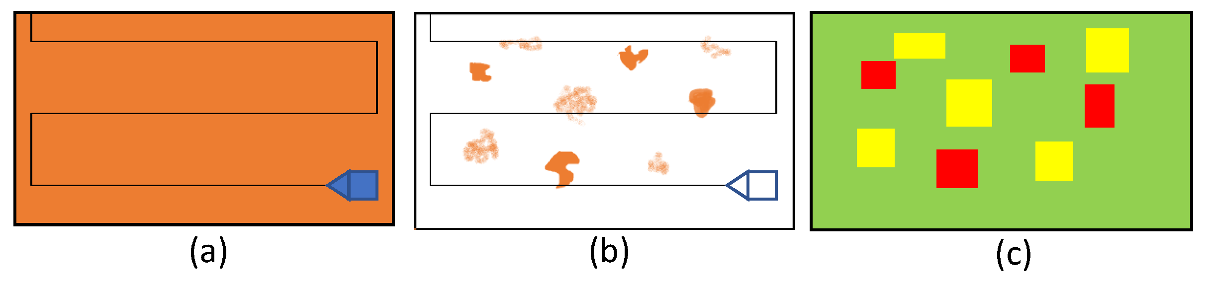
2.1. Context of Application
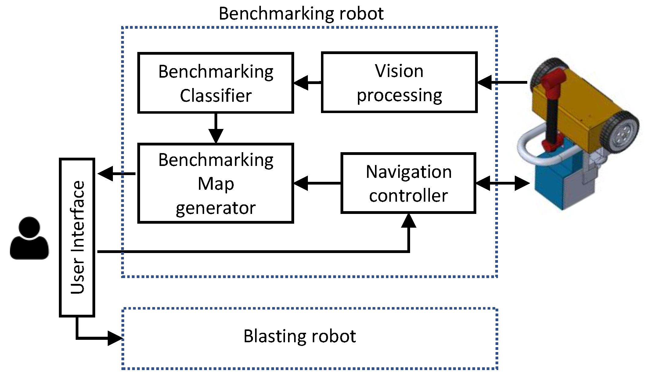
2.2. Functional Overview
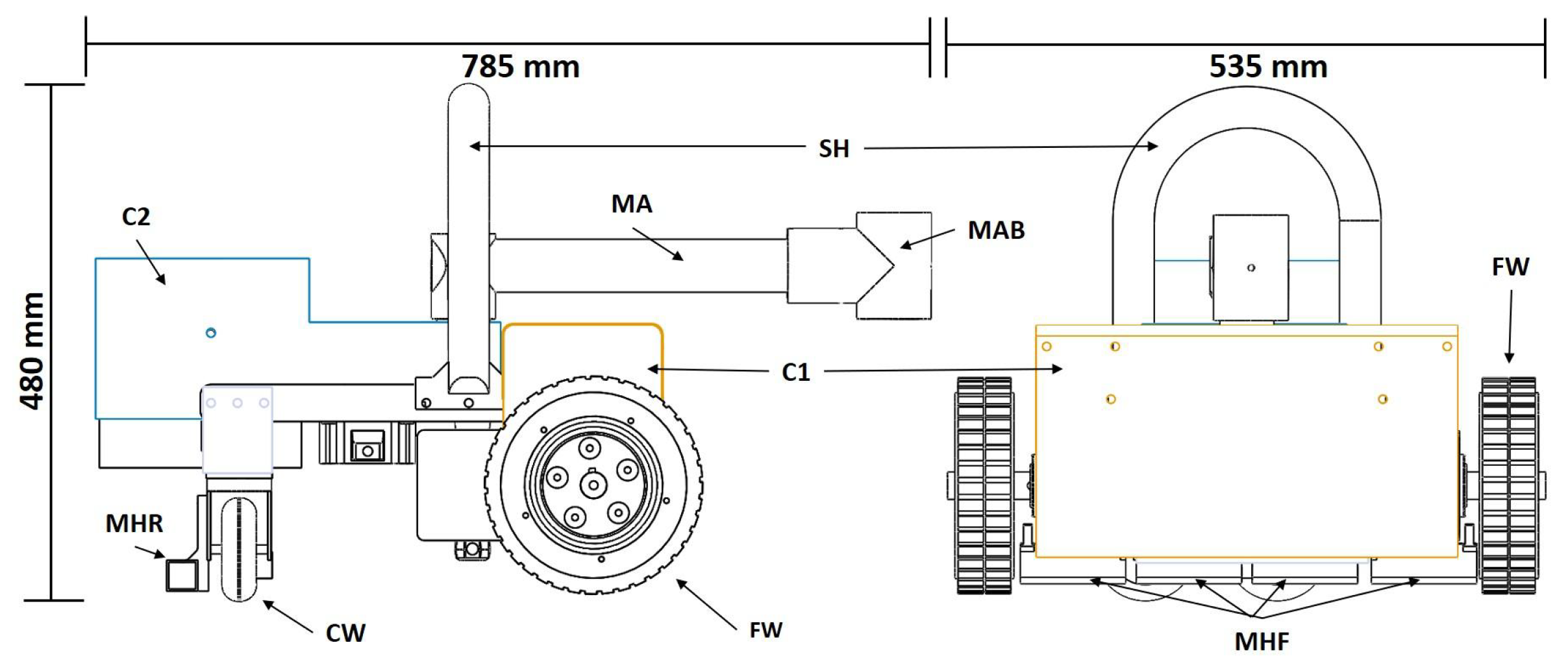
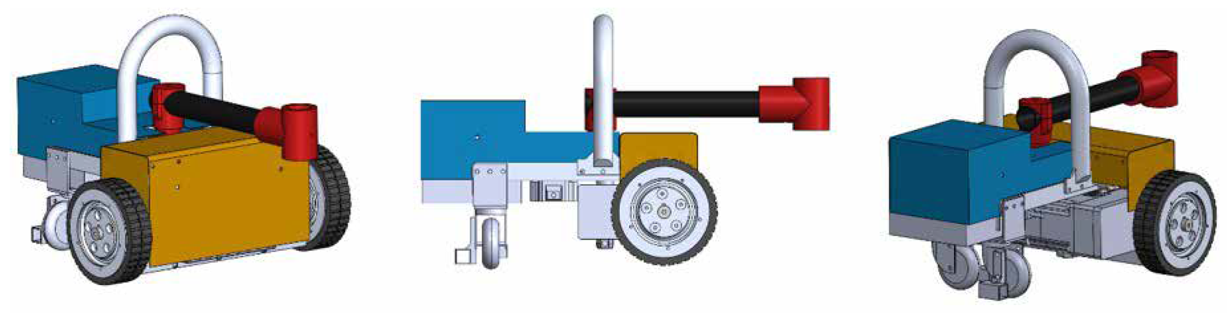
2.3. Robot Platform
3. Self-Organizing Fuzzy Logic (SOF) Classifier
- The benchmarking statuses are defined based on human expert knowledge, and the benchmarking categorization is performed based on the three fuzzy linguistic descriptors, good, medium, and bad. Moreover, the benchmarking classifier should emulate the human expert knowledge in the classification process. Fuzzy logic has been proven to be well suited for replicating the human expert knowledge that can be represented through linguistic expressions [32,33,34]. Furthermore, fuzzy logic has the ability to cope with imprecise sensor information [35,36,37]. Therefore, a method based on fuzzy concepts would be expected to perform well in this specific application.
- A human interpretable and explainable set of rules is generated after the training of a SOF classifier. Explainable intelligent techniques are preferred for ensuring transparency and trust of safety in this sort of industrial application, which might become hazardous from undesired control actions that might be performed by a robot [38]. Furthermore, the set of rules can be tailored based on expert knowledge.
- A SOF classifier is a highly efficient model with high classification accuracy [31,39]. Therefore, it requires lower computational power with respect to the other existing models. In addition to that, a SOF classifier does not require dedicated optimized hardware such as GPU cores for the computation. Moreover, a SOF model is comparatively lightweight.
- Many existing classification models rely heavily on prior assumptions on data generation models and user-defined trial and error parameters such as learning rate and the size of the network. In most of the practical cases, the assumptions on data generation are often too tough to be sustained, and user-defined parameters are often troublesome to define due to the insufficient prior knowledge of the problem. In contrast, a SOF classifier is nonparametric, and it does not require an assumption on data generation models and parameter knowledge about the problem of interest [31].
- Step 2: The sample is sorted according to the multimodal density and mutual distances calculated in step 1. The sorted sample set is denoted by , where is given in (5) and the rest are obtained as in (6). It should be notated that corresponding to is excluded in each run of (6), and the process is repeated for all the data in the sample.
- Step 3: The multimodal density set after the sorting in step 2 is taken as . The initial set of prototypes, is generated by considering the condition given in (7). Moreover, the local maxima of are taken for .
- Step 5: The set of centers of the formed data clouds, are identified. is equivalent to . The multimodal density at the center of cloud is calculated as in (9) where is the number of members in cloud, and n is the number of clouds formed.
- Step 6: The set of centers of neighboring data clouds of data cloud, is identified for each i based on the condition given in (10) such that and . Here, defines the average radius of local influential area around each data sample. This parameter is calculated iteratively as given in (11) based on the granularity level defined by user. Here, is the number of pairs of data samples where the distance between a pair is less than for . When , is the number of pairs of data samples where the distance between a pair is less than the average distance, .
- Step 7: The set of representative prototypes of class, are identified by evaluating the condition given in (12).
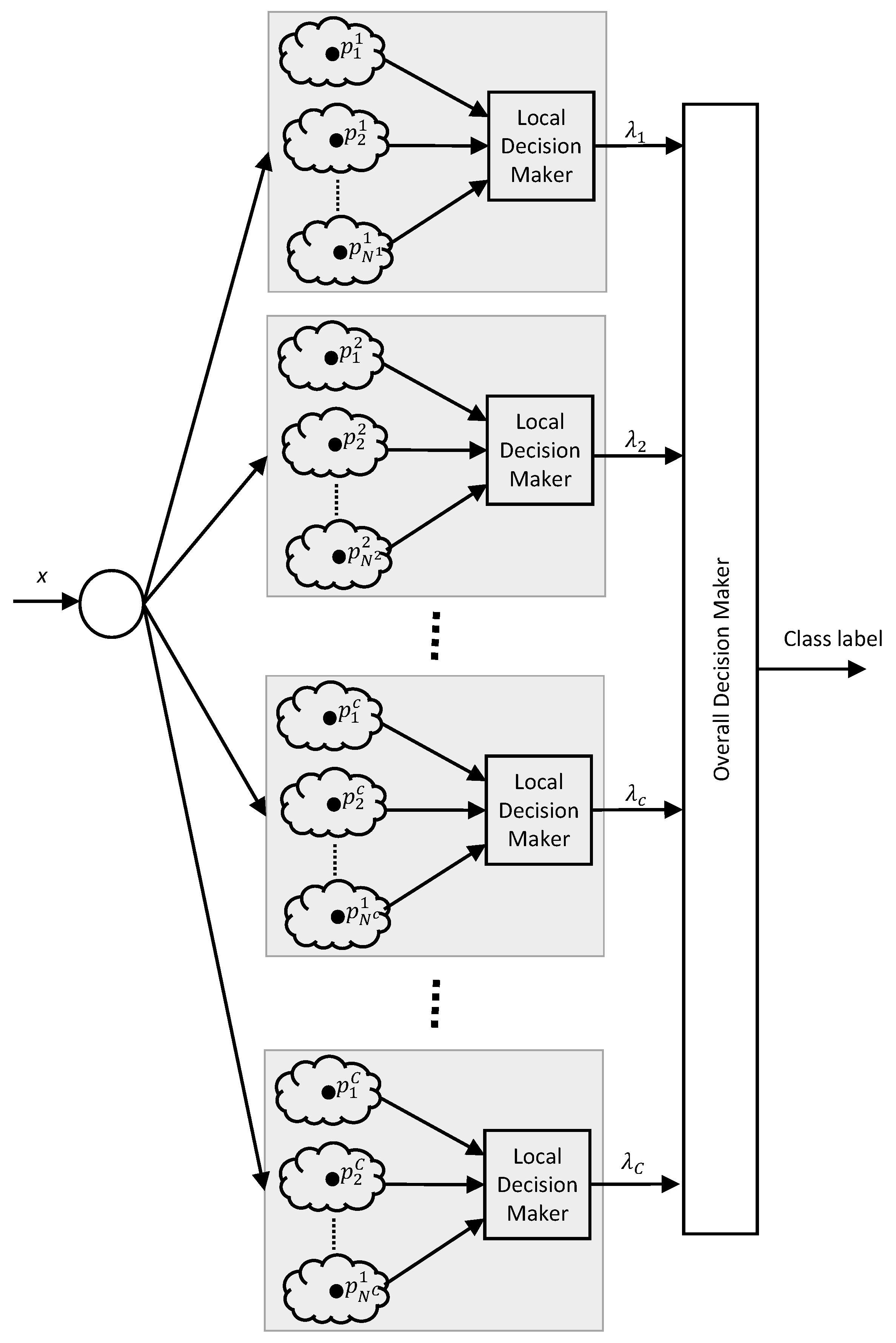
- Step 8: A zeroth order AnYa type fuzzy rule is created for class in the format given in (1), where is the number of representative prototypes.
4. Results and Discussion
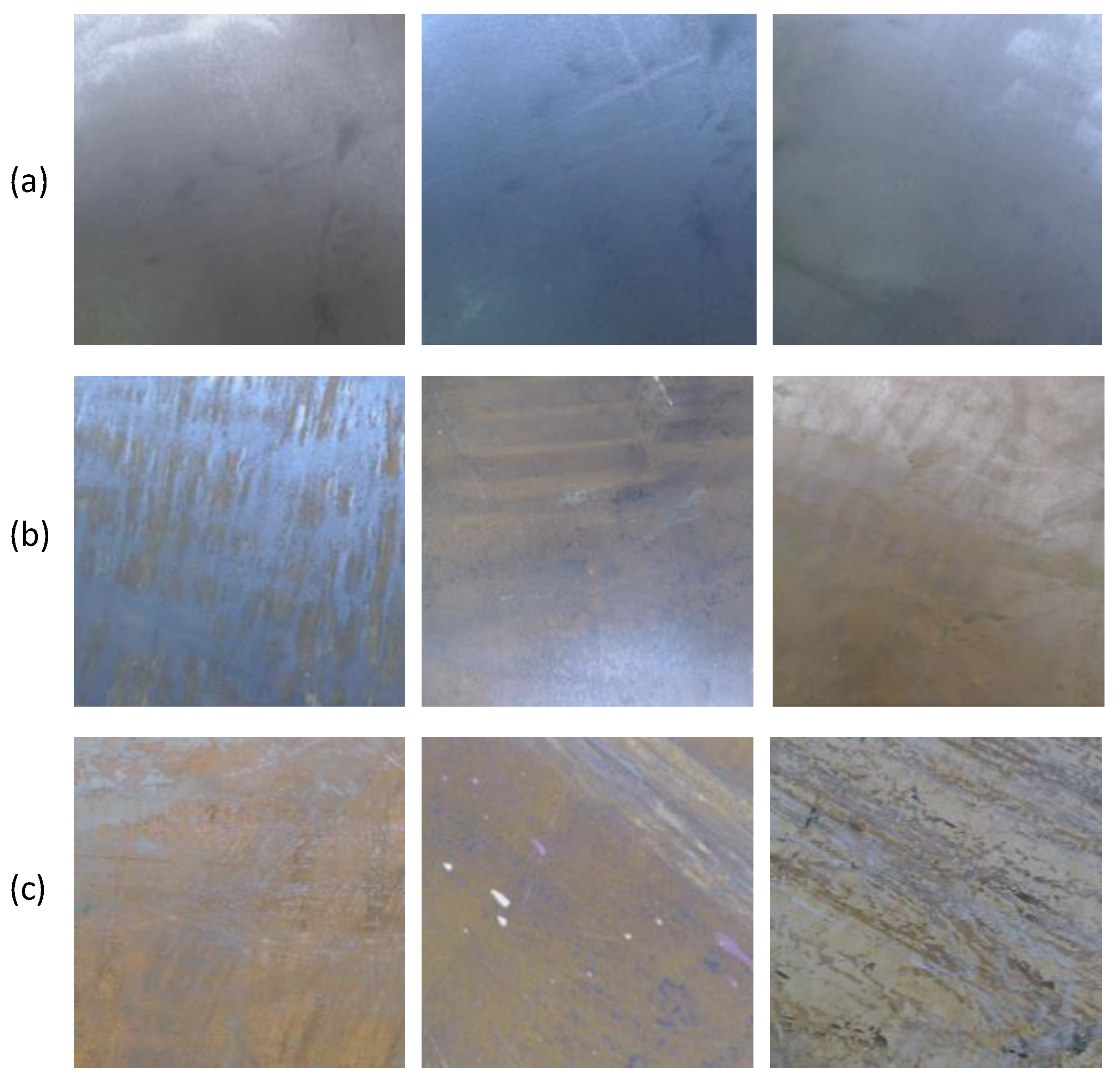
4.1. Data Collection and Training, and Classification Performance
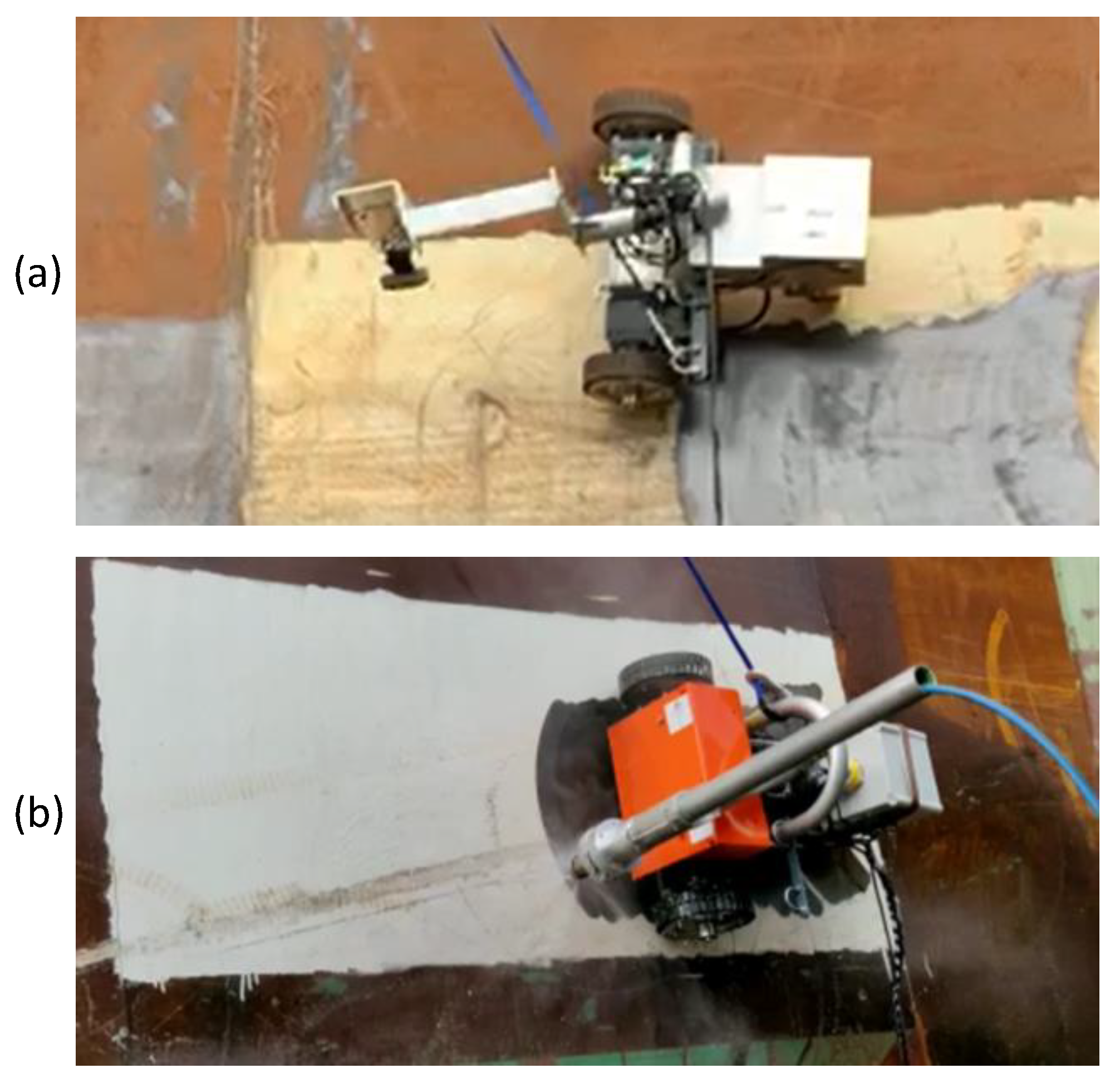
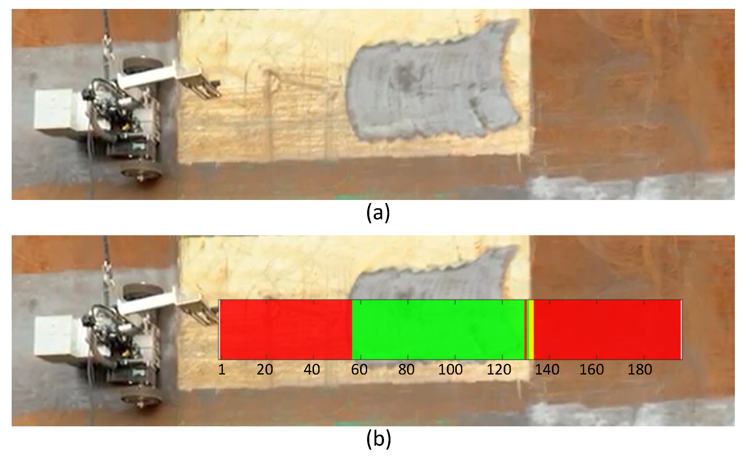
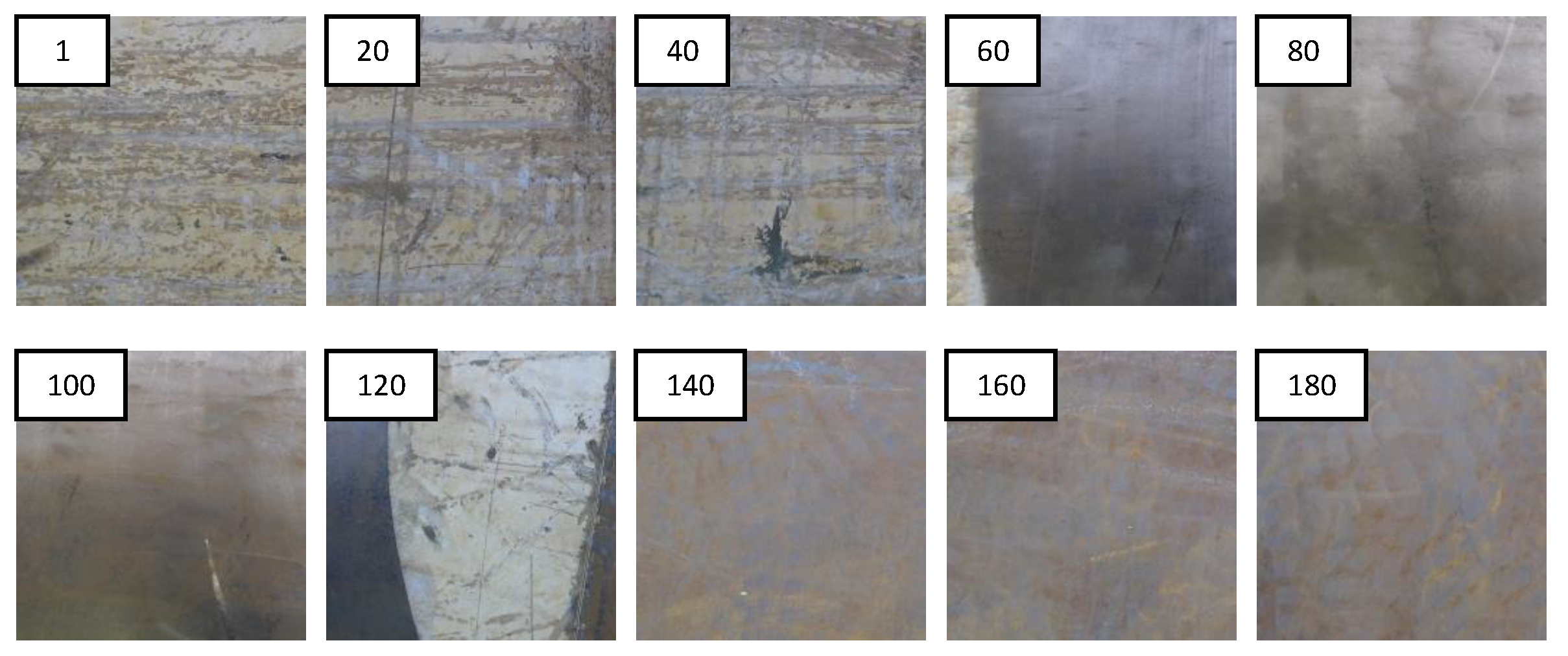
4.2. Realtime Operation on the Robot
5. Conclusions
Supplementary Materials
Author Contributions
Funding
Acknowledgments
Conflicts of Interest
References
- Garbatov, Y.; Sisci, F.; Ventura, M. Risk-based framework for ship and structural design accounting for maintenance planning. Ocean Eng. 2018, 166, 12–25. [Google Scholar] [CrossRef]
- Adland, R.; Cariou, P.; Jia, H.; Wolff, F.C. The energy efficiency effects of periodic ship hull cleaning. J. Clean. Prod. 2018, 178, 1–13. [Google Scholar] [CrossRef]
- Swain, G.; Lund, G. Dry-Dock Inspection Methods for Improved Fouling Control Coating Performance. J. Ship Prod. Des. 2016, 32, 186–193. [Google Scholar] [CrossRef]
- Gong, C.; Frangopol, D.M.; Cheng, M. Risk-based life-cycle optimal dry-docking inspection of corroding ship hull tankers. Eng. Struct. 2019, 195, 559–567. [Google Scholar] [CrossRef]
- Muthugala, M.A.V.J.; Vega-Heredia, M.; Vengadesh, A.; Sriharsha, G.; Elara, M.R. Design of an Adhesion-Aware Façade Cleaning Robot. In Proceedings of the 2019 IEEE/RSJ International Conference on Intelligent Robots and Systems (IROS), Macau, China, 3–8 November 2019; pp. 1441–1447. [Google Scholar]
- Le, A.V.; Nhan, N.H.K.; Mohan, R.E. Evolutionary Algorithm-Based Complete Coverage Path Planning for Tetriamond Tiling Robots. Sensors 2020, 20, 445. [Google Scholar] [CrossRef] [Green Version]
- Samarakoon, S.M.B.P.; Muthugala, M.A.V.J.; Le, A.V.; Elara, M.R. hTetro-Infi: A Reconfigurable Floor Cleaning Robot With Infinite Morphologies. IEEE Access 2020, 8, 69816–69828. [Google Scholar] [CrossRef]
- Muthugala, M.A.V.J.; Vega-Heredia, M.; Mohan, R.E.; Vishaal, S.R. Design and Control of a Wall Cleaning Robot with Adhesion-Awareness. Symmetry 2020, 12, 122. [Google Scholar] [CrossRef] [Green Version]
- Bonnin-Pascual, F.; Ortiz, A. On the use of robots and vision technologies for the inspection of vessels: A survey on recent advances. Ocean Eng. 2019, 190, 106420. [Google Scholar] [CrossRef]
- Hachicha, S.; Nejim, S.; Zaoui, C.; Maalej, A.; Dallagi, H. Study and modeling of a hull cleaning station with an arm manipulator. In Proceedings of the 2018 International Conference on Advanced Systems and Electric Technologies (IC_ASET), Hammamet, Tunisia, 22–25 March 2018; pp. 132–137. [Google Scholar]
- Zheng, X.; Lan, G.; Chew, C.M.; Lu, W.F. Design of a semi-automatic robotic system for ship hull surface blasting. In Proceedings of the 2016 IEEE 21st International Conference on Emerging Technologies and Factory Automation (ETFA), Berlin, Germany, 6–9 September 2016; pp. 1–4. [Google Scholar]
- Navarro, P.J.; Muro, J.S.; Alcover, P.M.; Fernández-Isla, C. Sensors systems for the automation of operations in the ship repair industry. Sensors 2013, 13, 12345–12374. [Google Scholar] [CrossRef] [PubMed] [Green Version]
- Li, X.; Alexander, A.A.; Liu, N.; Wang, S.; Sulaimee, N.H.B.; Wong, F.S.; Lu, W.F.; Chew, C.M. A Semi-Automatic System for Grit-Blasting Operation in Shipyard. In Proceedings of the 2018 IEEE 23rd International Conference on Emerging Technologies and Factory Automation (ETFA), Turin, Italy, 4–7 September 2018; Volume 1, pp. 1133–1136. [Google Scholar]
- Aijazi, A.; Malaterre, L.; Tazir, M.; Trassoudaine, L.; Checchin, P. Detecting and Analyzing Corrosion Spots on the Hull of Large Marine Vessels Using Colored 3d Lidar Point Clouds. ISPRS Ann. Photogramm. Remote Sens. Spat. Inf. Sci. 2016, 3, 153–160. [Google Scholar] [CrossRef]
- Caldwell, R. Hull inspection techniques and strategy-remote inspection developments. In SPE Offshore Europe Conference & Exhibition; Society of Petroleum Engineers: Richardson, TX, USA, 2017. [Google Scholar]
- Schmidt, D.; Berns, K. Climbing robots for maintenance and inspections of vertical structures—A survey of design aspects and technologies. Robot. Auton. Syst. 2013, 61, 1288–1305. [Google Scholar] [CrossRef]
- Brusell, A.; Andrikopoulos, G.; Nikolakopoulos, G. A survey on pneumatic wall-climbing robots for inspection. In Proceedings of the 2016 24th Mediterranean Conference on Control and Automation (MED), Athens, Greece, 21–24 June 2016; pp. 220–225. [Google Scholar]
- Garrido, G.G.; Sattar, T.; Corsar, M.; James, R.; Seghier, D. Towards safe inspection of long weld lines on ship hulls using an autonomous robot. In Proceedings of the 21st International Conference on Climbing and Walking Robots (CLAWAR 2018), Panamá, Panama, 10–12 September 2018. [Google Scholar]
- Ahmed, M.; Eich, M.; Bernhard, F. Design and Control of MIRA: A Lightweight Climbing Robot for Ship Inspection. In International Letters of Chemistry, Physics and Astronomy; Sci Press: Bach, Switzerland, 2015; Volume 55, pp. 128–135. [Google Scholar] [CrossRef]
- Stepson, W.; Amarasinghe, A.; Fernando, P.; Amarasinghe, Y. Design and development of a mobile crawling robot with novel halbach array based magnetic wheels. In Proceedings of the 2017 IEEE/RSJ International Conference on Intelligent Robots and Systems (IROS), Vancouver, BC, Canada, 24–28 September 2017; pp. 6561–6566. [Google Scholar]
- Huang, H.; Li, D.; Xue, Z.; Chen, X.; Liu, S.; Leng, J.; Wei, Y. Design and performance analysis of a tracked wall-climbing robot for ship inspection in shipbuilding. Ocean Eng. 2017, 131, 224–230. [Google Scholar] [CrossRef]
- Welch, H.; Mondal, S. Analysis of Magnetic Wheel Adhesion Force for Climbing Robot. J. Robot. Mechatron. 2019, 3, 534–541. [Google Scholar] [CrossRef]
- Xu, Z.; Xie, Y.; Zhang, K.; Hu, Y.; Zhu, X.; Shi, H. Design and optimization of a magnetic wheel for a grit-blasting robot for use on ship hulls. Robotica 2017, 35, 712–728. [Google Scholar] [CrossRef]
- Zhang, M.; Zhang, H.; Song, Q. Study on Negative Pressure Adsorption Characteristics of Ship Climbing Robot. In Proceedings of the 2017 International Conference on Computer Technology, Electronics and Communication (ICCTEC), Dalian, China, 19–21 December 2017; pp. 1061–1067. [Google Scholar]
- Milella, A.; Maglietta, R.; Caccia, M.; Bruzzone, G. Robotic inspection of ship hull surfaces using a magnetic crawler and a monocular camera. Sens. Rev. 2017, 37, 425–435. [Google Scholar] [CrossRef]
- Ahuja, S.K.; Shukla, M.K.; Ahuja, S.K.; Shukla, M.K. A survey of computer vision based corrosion detection approaches. In International Conference on Information and Communication Technology for Intelligent Systems; Springer: Berlin, Germany, 2017; pp. 55–63. [Google Scholar]
- Kumar, M.; Satyanarayana, K.V.V.; Ramesh, A.P. Surface Corrosion Grade Classification using Convolution Neural Network. Int. J. Recent Technol. Eng. 2019, 8, 7645–7649. [Google Scholar]
- Jalalian, A.; Lu, W.; Wong, F.; Ahmed, S.; Chew, C.M. An Automatic Visual Inspection Method based on Statistical Approach for Defect Detection of Ship Hull Surfaces. In Proceedings of the 2018 IEEE 14th International Conference on Automation Science and Engineering (CASE), Munich, Germany, 20–24 August 2018; pp. 445–450. [Google Scholar]
- Ortiz, A.; Bonnin-Pascual, F.; Garcia-Fidalgo, E. Visual inspection of vessels by means of a micro-aerial vehicle: An artificial neural network approach for corrosion detection. In Robot 2015: Second Iberian Robotics Conference; Springer: Berlin, Germany, 2016; pp. 223–234. [Google Scholar]
- Fernández-Isla, C.; Navarro, P.J.; Alcover, P.M. Automated visual inspection of ship hull surfaces using the wavelet transform. Math. Probl. Eng. 2013, 2013. [Google Scholar] [CrossRef]
- Gu, X.; Angelov, P.P. Self-organising fuzzy logic classifier. Inf. Sci. 2018, 447, 36–51. [Google Scholar] [CrossRef] [Green Version]
- De Silva, C.W. Intelligent Control: Fuzzy Logic Applications; CRC Press: Boca Raton, FL, USA, 2018. [Google Scholar]
- Zadeh, L.A. Is there a need for fuzzy logic? Inf. Sci. 2008, 178, 2751–2779. [Google Scholar] [CrossRef]
- Muthugala, M.A.V.J.; Vengadesh, A.; Wu, X.; Elara, M.R.; Iwase, M.; Sun, L.; Hao, J. Expressing attention requirement of a floor cleaning robot through interactive lights. Autom. Constr. 2020, 110, 103015. [Google Scholar] [CrossRef]
- Ross, T.J. Fuzzy Logic with Engineering Applications; John Wiley & Sons: Hoboken, NJ, USA, 2005. [Google Scholar]
- Muthugala, M.A.V.J.; Srimal, P.H.D.; Jayasekara, A.G.B.P. Enhancing interpretation of ambiguous voice instructions based on the environment and the user’s intention for improved human-friendly robot navigation. Appl. Sci. 2017, 7, 821. [Google Scholar] [CrossRef] [Green Version]
- Muthugala, M.A.V.J.; Jayasekara, A.G.B.P. Improving the understanding of navigational commands by adapting a robot’s directional perception based on the environment. J. Ambient Intell. Smart Environ. 2019, 11, 135–148. [Google Scholar] [CrossRef]
- Hagras, H. Toward Human-Understandable, Explainable AI. Computer 2018, 51, 28–36. [Google Scholar] [CrossRef]
- Du, W.; Guo, X.; Wang, Z.; Wang, J.; Yu, M.; Li, C.; Wang, G.; Wang, L.; Guo, H.; Zhou, J.; et al. A New Fuzzy Logic Classifier Based on Multiscale Permutation Entropy and Its Application in Bearing Fault Diagnosis. Entropy 2020, 22, 27. [Google Scholar] [CrossRef] [Green Version]
- Angelov, P.; Yager, R. A new type of simplified fuzzy rule-based system. Int. J. Gen. Syst. 2012, 41, 163–185. [Google Scholar] [CrossRef]
- Angelov, P.P.; Gu, X.; Príncipe, J.C. A generalized methodology for data analysis. IEEE Trans. Cybern. 2017, 48, 2981–2993. [Google Scholar] [CrossRef] [Green Version]
- Okabe, A.; Boots, B.; Sugihara, K.; Chiu, S.N. Spatial Tessellations: Concepts and Applications of Voronoi Diagrams; John Wiley & Sons: Hoboken, NJ, USA, 2009; Volume 501. [Google Scholar]


| Distance Measure | Euclidean | Cosine | ||||
|---|---|---|---|---|---|---|
| L | 4 | 8 | 12 | 4 | 8 | 12 |
| Accuracy | 0.9744 | 0.9942 | 0.9928 | 0.9779 | 0.9915 | 0.9933 |
| t (µs) | 2.86 | 8.67 | 23.8 | 6.56 | 10.31 | 11.04 |
| Actual | ||||
|---|---|---|---|---|
| Good | Medium | Bad | ||
| Predicted | Good | 370 | 4 | 0 |
| Medium | 0 | 366 | 1 | |
| Bad | 0 | 0 | 369 | |
© 2020 by the authors. Licensee MDPI, Basel, Switzerland. This article is an open access article distributed under the terms and conditions of the Creative Commons Attribution (CC BY) license (http://creativecommons.org/licenses/by/4.0/).
Share and Cite
Muthugala, M.A.V.J.; Le, A.V.; Cruz, E.S.; Rajesh Elara, M.; Veerajagadheswar, P.; Kumar, M. A Self-Organizing Fuzzy Logic Classifier for Benchmarking Robot-Aided Blasting of Ship Hulls. Sensors 2020, 20, 3215. https://doi.org/10.3390/s20113215
Muthugala MAVJ, Le AV, Cruz ES, Rajesh Elara M, Veerajagadheswar P, Kumar M. A Self-Organizing Fuzzy Logic Classifier for Benchmarking Robot-Aided Blasting of Ship Hulls. Sensors. 2020; 20(11):3215. https://doi.org/10.3390/s20113215
Chicago/Turabian StyleMuthugala, M. A. Viraj J., Anh Vu Le, Eduardo Sanchez Cruz, Mohan Rajesh Elara, Prabakaran Veerajagadheswar, and Madhu Kumar. 2020. "A Self-Organizing Fuzzy Logic Classifier for Benchmarking Robot-Aided Blasting of Ship Hulls" Sensors 20, no. 11: 3215. https://doi.org/10.3390/s20113215