1. Introduction
Micro fluidic channel fabrication technologies play a key role in many of today's industrial areas, including the energy and bio technology fields where they are employed in the fabrication of micro fuel cells and biochips with higher efficiency. Commonly required technological features of such products are size miniaturization, multi-functional structure, and power consumption reduction. In the near future, it will be necessary to manufacture such products with higher efficiency, greater precision, and smaller size.[
1∼
5] To achieve these goals, it is important to develop more competitive micro structure fabrication technologies that offer advantages in cost, time, and flexibility. Chemical etching processes have been widely used to fabricate micro structures and/or patterns. However, chemical etching may lead to undesired undercutting or overetching due to solution density or reaction time variation, and it is carried out in a harmful environment.
Thus, in this study, a powder blasting method, a type of mechanical etching process, is applied for micro fluidic channel fabrication. In the process, material removal is performed by the collision of micro abrasives injected by highly compressed air on to the target surface. This approach can be characterized as an integration of brittle mode machining based on micro crack propagation.[
6∼
9] Fused silica glass, which is a high purity synthetic amorphous silicon dioxide (SiO
2), is used as a target material for micro channel fabrication. It has a very low thermal expansion coefficient with excellent optical qualities and exceptional transmittance over a wide spectral range, especially in the ultraviolet range. It can be used for biochips, lenses, and prisms in a transmission range of 0.16μm to 3μm. Micro channels are machined on fused silica glass via a powder blasting method and their characteristics are experimentally evaluated. In the process, process parameters such as injection pressure, abrasive particle size and density, stand-off distance and scanning times of the nozzle, and patterns shapes and size affect the machined results. [
10∼
13] In this study, the influence of the number of nozzle scanning, abrasive particle size, and pattern size on the pattern formation is investigated. Machined shapes and surface roughness are measured using a 3-dimensional vision profiler and the results are discussed.
2. Material Properties of Fused Silica Glass
Fused silica glass is a high purity synthetic amorphous silicon dioxide (SiO
2). It can be obtained by electric arc melting high purity sand deposits at extremely high temperature (above 2000°C). It has a highly cross linked 3-dimensional structure. This noncrystalline, colorless, silica glass combines a very low thermal expansion coefficient with excellent optical qualities and exceptional transmittance over a wide spectral range, especially in the ultraviolet. It is resistant to scratching and thermal shock. Fused silica glass can be used for different applications and is available with various grades. One of its important applications is high energy laser optics. No other optical material matches the purity of fused silica, and therefore its ability to withstand and transmit high energy laser pulses with limited absorption or damage to the material is similarly unrivaled. Fused silica glass can also be used for biochips, lenses, and prisms in a transmission range of 0.16μm to 3μm. Its refractive index varies from 1.55 to 1.40 through the transmission range. Material properties of the used fused silica glass are presented in
Tables 1 and
2.
3. Basic principles of the Powder Blasting
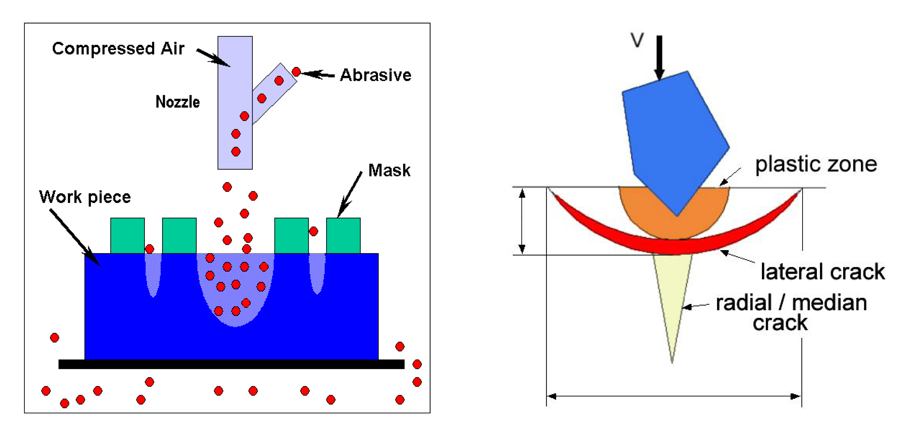
In the powder blasting process, micro abrasives (tens of μm), accelerated by highly compressed air or gases, are forced through a ceramic nozzle, and collide with a workpiece at a very high velocity (80 – 200m/s) and density. The nozzle can be moved along the X- and Y-directions to scan surface areas. The workpiece is covered with a patterned mask; thus, the open areas of the workpiece are removed by the injected abrasive particles. Since the material removal process of powder blasting is performed by a type of brittle mode machining based on micro crack propagation, there is very little heat, chipping, or crack generation in the workpiece. Thus, this method is suitable for the machining of micro shapes (such as grooves, holes, pockets, etc.) of hard and brittle materials (such as glass, ceramics, silicon, crystal, etc.). A rebounded mixture of abrasives and chips from the workpiece is sent to the distributor, which then separates the mixture into chips and abrasives for recycling.
The process parameters of powder blasting are: (1) blasting pressure, time, and velocity; (2) material properties, size and density of the abrasives; (3) velocity and number of nozzle scanning; and (4) stand-off distance (distance between the nozzle and workpiece). These parameters should be appropriately determined to improve machining accuracy and efficiency. The basic principle of the machining process is illustrated in
Figure 1.
4. Experimental Methods
4.1. Specimen Preparation
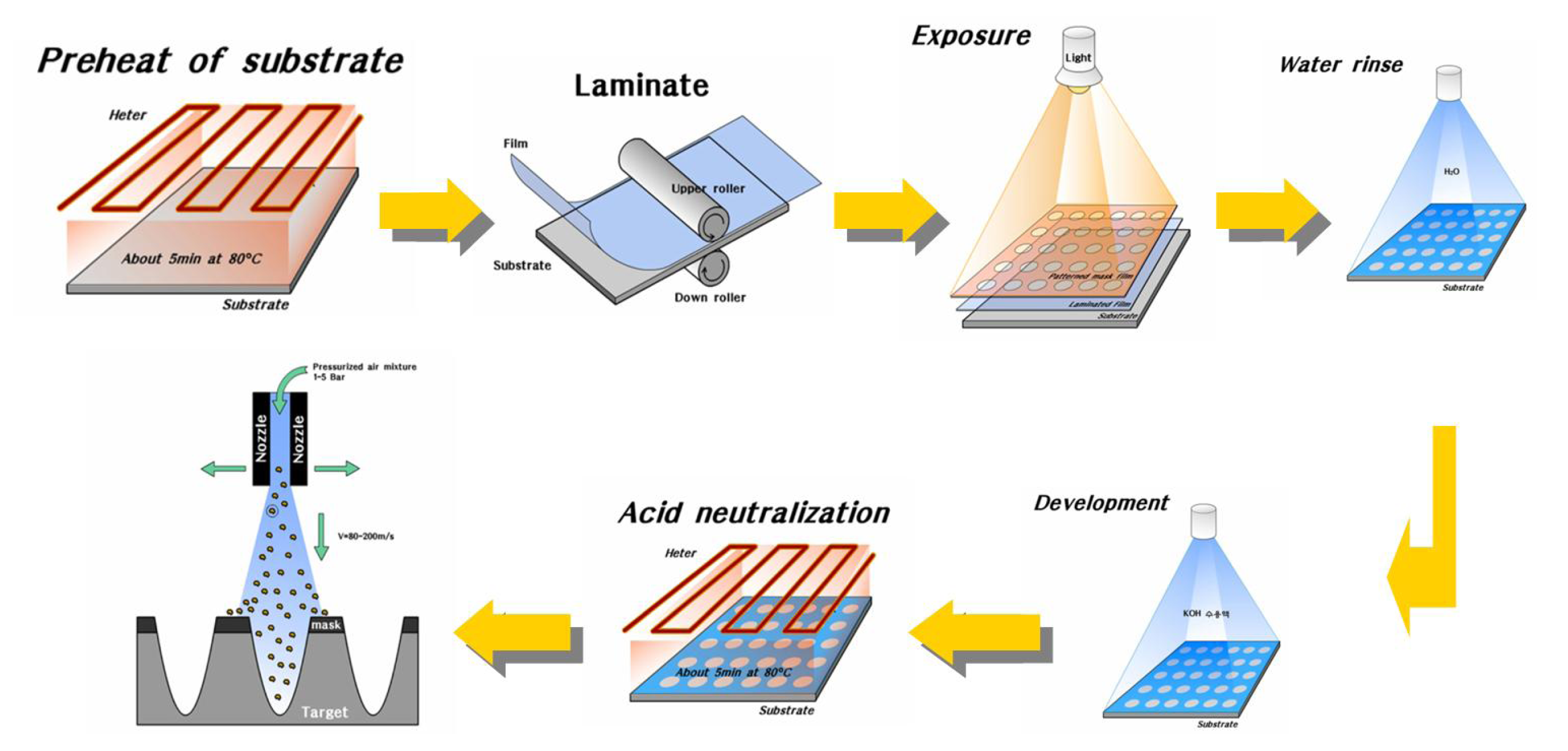
The process flow of the micro channel fabrication process using powder blasting is illustrated in
Figure 2. The procedure can be described as follows.
Micro pattern design
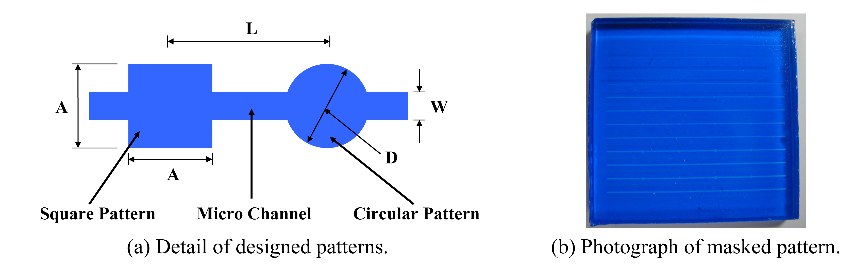
Figure 3(a) shows the details of the designed micro patterns and micro channels; square and circular patterns are designed for biochip application. Two types of patterns are designed: 200μm channels (W=200μm, A=D=400μm and L=8mm) and 300μm channels (W=300μm, A=D=600μm and L=8 mm). These patterns are used for the masking process.
Masking process
The purpose of the masking process is to prepare required specimens with micro patterns. A dry film is used for the masking process. The film thickness influences the resolution and accuracy of the machined shapes. UV hardening polyurethane is used as a film material to provide wear-resistance during the process. The details of the applied masking process are as follows:
- -
Laminating: A film is adhered to the workpiece.
- -
Exposure: A parallel UV beam is irradiated to make required patterns.
- -
Developing: The specimen is developed using a developing solution, which is composed of distilled water and a 5% Na2CO3 solution. Finally, required patterns can be obtained by removing the masks from the desired regions.
Figure 3(b) shows a photograph of a specimen after the masking process.
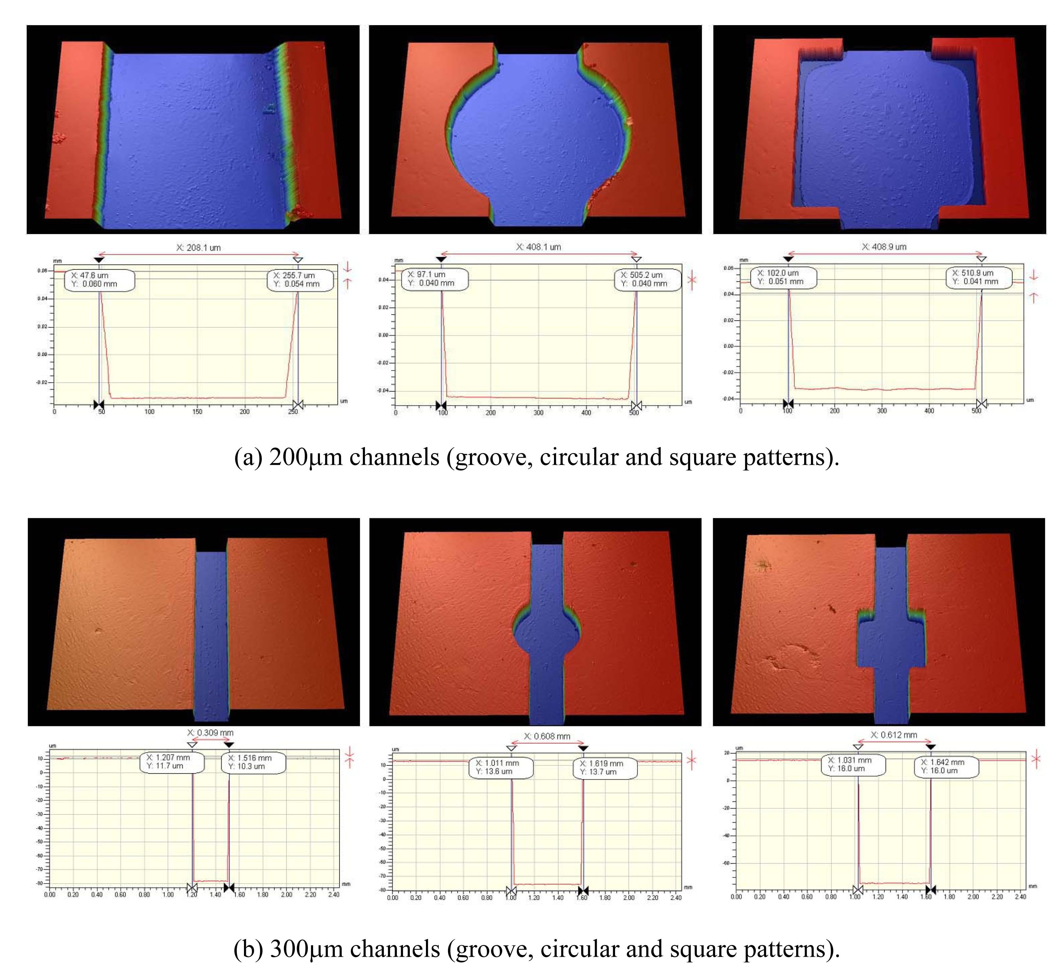
Figure 4 shows measured 3-dimensional shapes and cross-sectional profiles of the masks formed on the glass. From the results, it is found that the measured width of the masked pattern is about 10μm larger than the designed value. This discrepancy is attributed to errors such as resolution difference, light dispersion in the exposure process, etc.
Powder blasting process
Powder blasting is performed on the machine. Here, the regions from which the masks are removed in the developing process are selectively machined.
Mask removing and cleaning process
After the machining process is finished, any remaining mask adhering to the workpiece surface is removed, and the workpiece is cleaned using ultrasonic cleaning equipment.
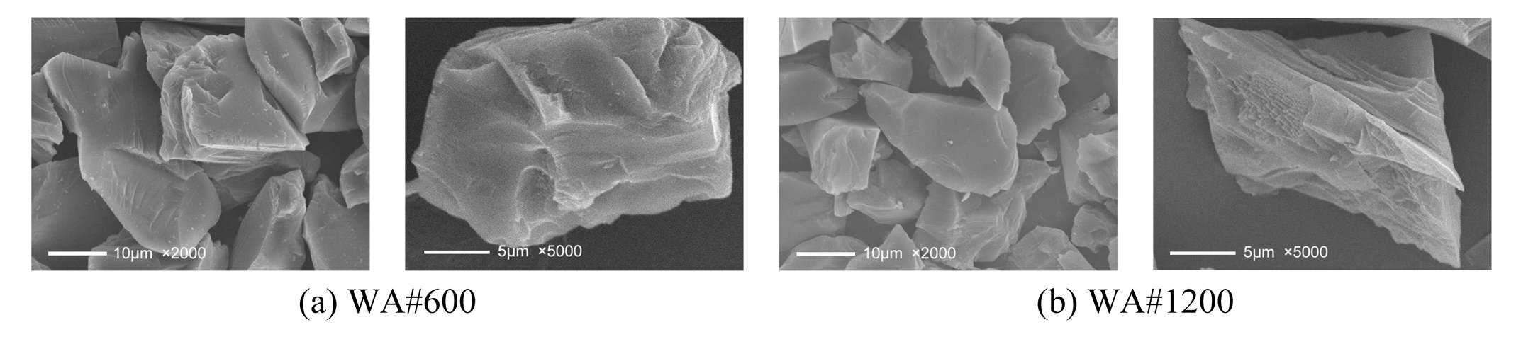
4.2. Abrasive Particles
Two types of abrasives, WA#600 and #1200, are used for the micro powder blasting experiments. WA denotes white alundum, and its main ingredient is Al
2O
3.
Figure 5 shows SEM micrographs of the employed abrasive particles.
4.3. Experimental Conditions
All experiments in this study are performed using MICROBLASTER (type MB1, Japan), which has a ceramic injection nozzle with an 8mm inner diameter. After powder blasting, the machined pattern shapes are measured and investigated using a 3-dimensional measuring device (WYCO NT-2000) and SEM (Jeol JSM-5200 scanning microscope).
5. Experimental Results
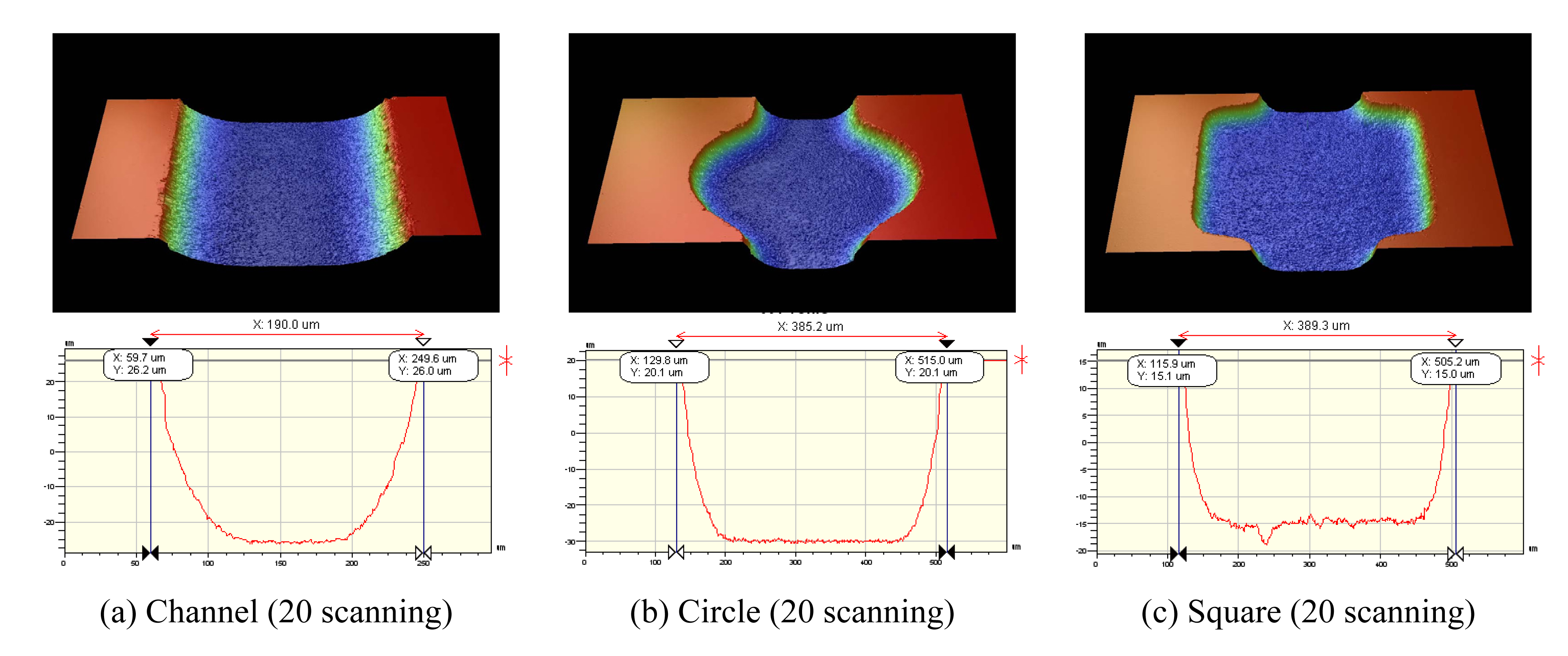
Figure 6 and
7 show the machined results of 200μm channels obtained under the experimental conditions listed in
Table 4. Formed pattern shapes are measured using WYCO NT-2000 and WYCO Vision32. From the figure, it can be observed that the groove shapes are formed very well, and have U-shape cross-sections due to the material removal characteristics of the applied powder blasting method.
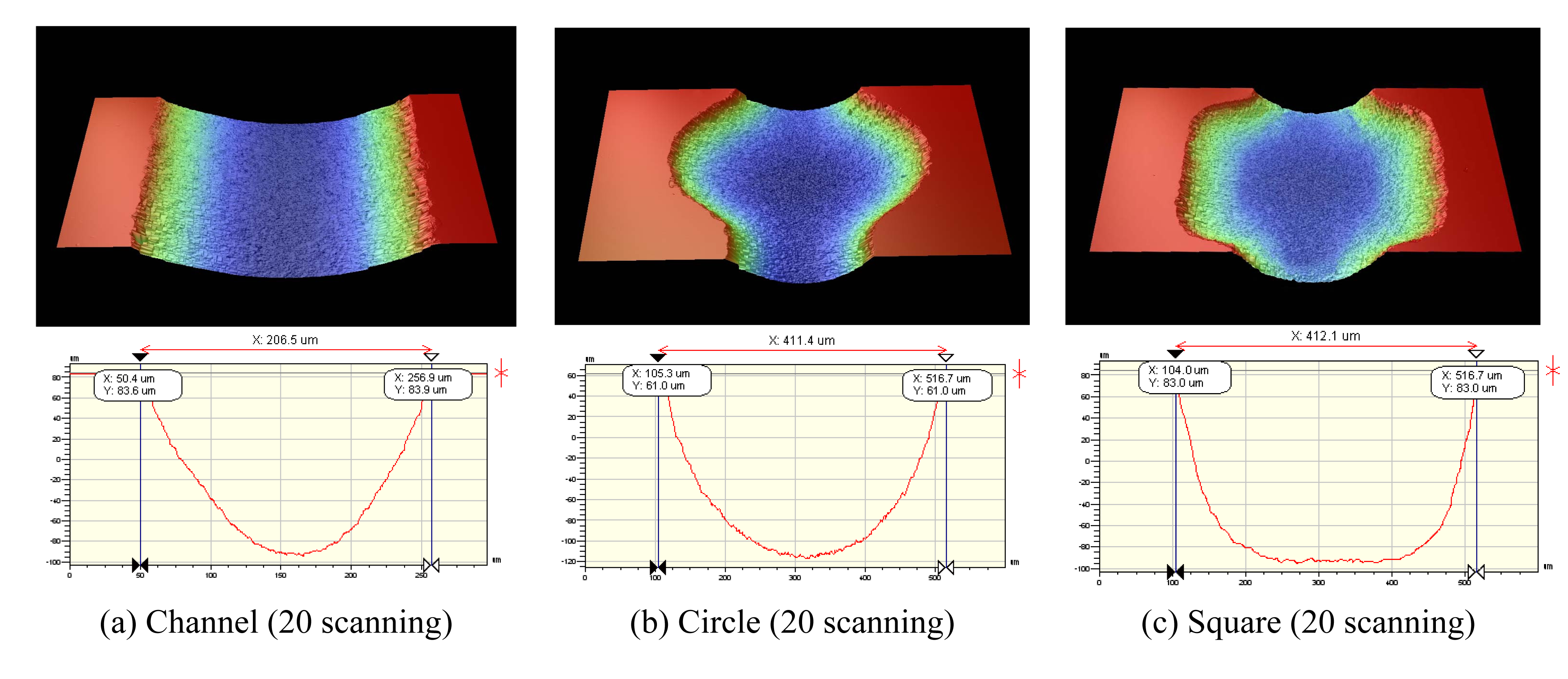
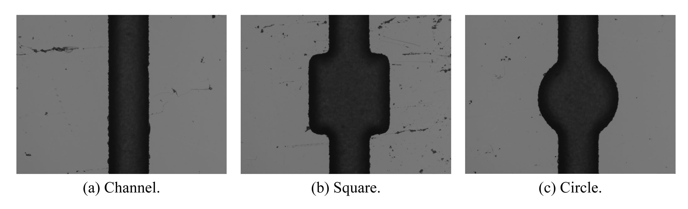
Figures 8 and
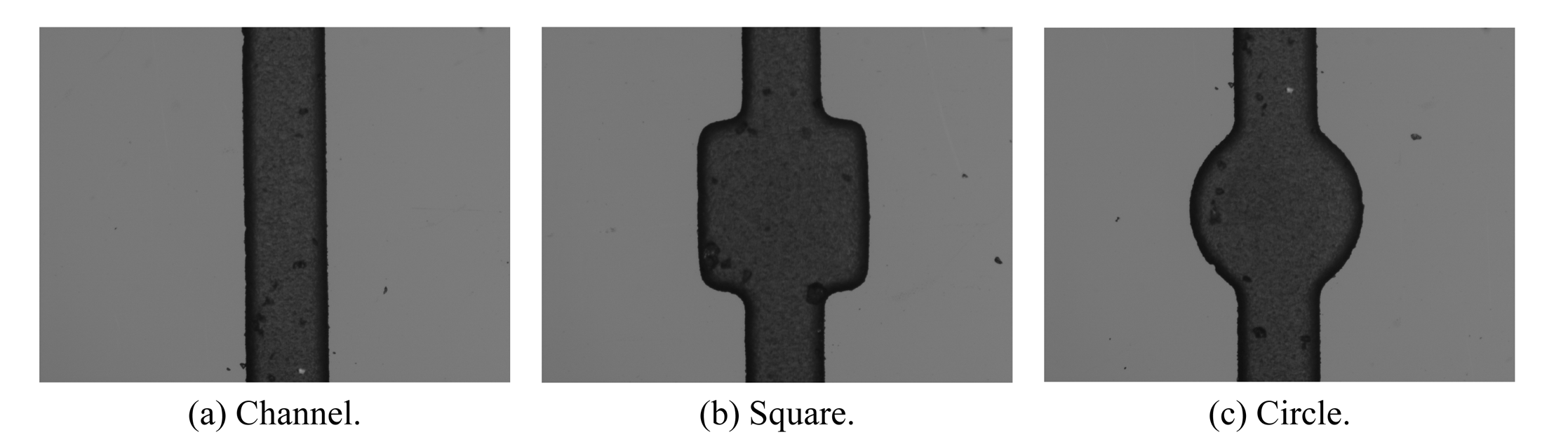
9 show magnified top-view images of channels, square and circular patterns included in the 300μm channels, which are designed to simulate reservoirs in biochips. The images are obtained using 3D Micro-Vision System.
Figure 10 shows machined shape variations according to increasing scanning counts for 400μm circular pattern when (a) WA#600 and (b) WA#1200 abrasives are used. Measured machined depth and width variations of 200μm and 300μm channels are listed in
Table 5 and
6, respectively. From these results, it can be seen that the machining capability of WA#600 is higher than that of WA#1200; the rate of the depth increase rises with increased scanning and abrasive size. Also, in
Figure10, it can be observed that the machined width increases as scanning count increases. This is because the edges of used mask film (UV hardening polyurethane) are easily eroded by injected powder impact; thus, film thickness reduces rapidly, and top width of a channel increases during blasting.
Figure 11 shows machined depth variation according to increasing number of nozzle scanning for (a) 200μm and (b) 300μm channels, respectively. In the figure, it can be observed that the machined depth after 20th scan deviates a little from the linearity. This is due to the “blast lag effect”, which is caused by the increase of particle impact angle to sidewall as masked line width increases. [
10] The smaller the channel, the sooner this effect occurs. The top width of a channel increases during blasting, thus increasing rate of the erosion depth is accelerated.
Figure 12 shows the variation of the micro channel width for the (a) 200μm and (b) 300μm cases. From the figures, it can be observed that the machined depths and widths increase in proportion to the number of scanning.
From the experimental results, it is found that the machined results vary with the imposed powder blasting process parameters such as abrasive particle size, number of nozzle scanning, etc. Thus, determination of optimum process conditions is very important when applying the powder blasting method to fabricate micro channels on fused silica glass. The experimental results in this study can be useful to achieve more satisfactory powder blasting results in related fields.
6. Conclusions
Through this experimental study to examine the effects of variation of process parameters on the characteristics of micro patterns machined in fused silica glass via a powder blasting process, the following conclusions can be obtained.
- (1)
In the micro pattern masking process, masking errors of roughly 10 μm were detected for all types of the designed channel width. For further research, more precise masking techniques should be applied.
- (2)
Overall, the measured micro channels show U-shape cross-sections due to the material removal characteristics of the applied powder blasting method. It was found that the machined depths increase in proportion to an increase of the number of nozzle scanning.
- (3)
Machined depths of circular and square type patterns increase in proportion to an increase of the number of nozzle scanning. It was found that more precise patterns could be obtained by increasing the number of nozzle scanning.
- (4)
The size of the employed abrasives, one of the process parameters in powder blasting, affects the machinability of the workpiece; larger abrasive size results in deeper and wider material removal, and a higher increasing rate of depth.


