Parametric Study on EGR Cooler Fouling Mechanism Using Model Gas and Light-Duty Diesel Engine Exhaust Gas

1
LG Chem. R&D Campus Gwacheon 36, Janggunmaeul 3-gil, Gwacheon-si, Gyeonggi-do 13813, Korea
2
Department of Automotive Engineering, Gyonggi College of Science and Technology, 2121-3 Jeongwang-dong, Siheung-si, Gyeonggi-do 15073, Korea
3
Department of Mechanical Engineering, Chosun University, 303 Pilmun-daero, Dong-Gu, Gwangju 61452, Korea
*
Author to whom correspondence should be addressed.
Energies 2018, 11(11), 3161; https://doi.org/10.3390/en11113161
Submission received: 11 October 2018
/
Revised: 29 October 2018
/
Accepted: 9 November 2018
/
Published: 15 November 2018
Abstract
:Exhaust gas recirculation (EGR) and high-pressure fuel injection are key technologies for reducing diesel engine emissions in the face of reinforced regulations. With the increasing need for advanced EGR technologies to achieve low-temperature combustion and low emission, the adverse etableffects of EGR must be addressed. One of the main problems is fouling of the EGR cooler, which involves the deposition of particulate matter (PM) due to the thermophoretic force between the cooler wall and flow field. A large amount of deposited PM can reduce the effectiveness of the heat exchanger in the EGR cooler and the de-NOx efficiency. In the present study, the effects of the variables that affect EGR cooler fouling are investigated by a comparison of laboratory-based and engine-based experiments. In the laboratory experiment, a soot generator that could readily provide separate control of the variables was used to generate the model EGR gas. Through control of the soot generator, it was possible to perform a parametric study by varying the particle size, the EGR gas flow rate, and the coolant temperature as the dominant parameters. A decrease in these factors caused an increase in the mass of the deposit and a drop in the effectiveness of the heat exchanger, related to fouling of the EGR cooler. In the engine-based experiment, engine-like conditions were provided to analyze real exhaust gas without a soot generator. Different variables were found to induce fouling of the EGR cooler, and the results of the engine-based experiment differed from those of the laboratory experiment. For example, in the engine-based experiment, a decrease in the EGR gas flow rate did not lead to a more pronounced drop in the effectiveness of the heat exchanger because of the increase in the concentration of PM in the EGR gas. This result shows that the conditions of the engine exhaust gas are different from those of the soot generator.
1. Introduction
The diesel engine offers several advantages over the gasoline engine in terms of combustion efficiency, fuel consumption, and durability. The former is also favorable in terms of environmental considerations because it discharges less carbon dioxide (CO2), carbon monoxide (CO), and total hydrocarbon (THC) than the gasoline engine. However, the diesel engine is also a major source of nitrogen oxides (NOx) and particulate matter (PM) in urban areas. Due to its harmful effects on the environment and human health, many countries have enforced stringent legislation on diesel engine emissions [1,2]. In order to satisfy the requirements of the regulations, NOx and soot emissions must simultaneously be reduced, and exhaust gas recirculation (EGR) is one method of achieving this goal.
EGR technology reduces NOx emission by lowering the flame temperature in the cylinder and the oxygen concentration. Cooled-EGR technology has been used to further reduce the rate of NOx emission [3,4]. Zeng et al. reported that the main effects of EGR are the dilution effect, whereby the O2 concentration in the cylinder is lowered, the chemical effect owing to the higher heat capacity of recirculated product gases such as H2O and CO2, and the thermal effect caused by the EGR cooler [3].
The thermal effect is influenced by a high concentration of particles in the EGR gas, where the particles may deposit on the wall of the EGR cooler, a phenomenon termed EGR cooler fouling. EGR cooler fouling reduces the efficiency of heat transfer by the heat exchanger, thereby increasing the emission of NOx [5,6,7]. Hoard et al. reported that the soot deposits in EGR coolers cause significant degradation of the heat transfer efficiency, often on the order of 20−30% [5]. Deposits also increase the pressure drop across the EGR cooler, resulting in an unsatisfactory EGR rate and engine efficiencies under some operating conditions [6,7].
For this reason, EGR cooler fouling has been widely studied with respect to various parameters [8,9,10,11,12,13,14]. Such studies show that fouling phenomena related to the mass of volatile and non-volatile deposits may be affected by the thermal conductivity of the cooler material and the deposit composition [8], and by the cooler geometry (i.e., cylindrical and finned tube [9] structures) and the inner structure of the cooler [10], which may have limited thermal resistance as heat exchangers [11]. The layout of EGR systems must be optimized by considering the mass flow rate and coolant temperature [12,13,14].
However, most previous studies have focused on experimental analysis of the effects of EGR cooler fouling on the performance of the engine and NOx emission. Further, it is difficult to evaluate the effect of variables on fouling of the EGR cooler because several variables are coupled to each other. Therefore, fundamental investigation of the apparent interactions between such parameters is important for understanding EGR cooler fouling.
In our previous research, a laboratory experiment was conducted by using a PM generator [15] that offers the advantage of independent control of various variables that cannot be controlled in the engine-bench experiment. However, it is difficult to completely replicate the exhaust gas of the engine under various engine conditions.
The purpose of this study is to evaluate the effects of different variables (coolant temperature and flow rate) on EGR cooler fouling using exhaust gas from an engine and to compare the results of laboratory and engine-bench experiments. In addition, the effects of the DOC (diesel oxidation catalytic converter) catalyst on EGR cooler fouling are evaluated.
2. Materials and Methods
2.1. Measurement Apparatus for Lab-Scale Experiments
Figure 1 presents a schematic diagram of the laboratory experimental system. Laboratory experiments were conducted to study the effects of the variables (coolant temperature and flow rate) and DOC catalyst on EGR cooler fouling. As shown in the figure, the main components used for the lab-scale test were a propane (C3H8)-fueled soot generator, single channel EGR cooler, DOC bed, water circulator, data acquisition board, and other auxiliary components.
By providing engine-out conditions, the propane (C3H8)-fueled soot generator allows for independent control of the environmental variables, such as providing a constant particle size, concentration, mass flow rate, and coolant and gas temperatures. The model propane gas was controlled by a mass flow controller (MFC). The DOC bed was operated without and with a Pt catalyst. EGR gas was maintained at 380 °C by insulating the upstream of the DOC bed. A more detailed description of the lab-scale apparatus can be found in our previous publication [15].
2.2. Measurement Apparatus for Engine-Bench Experiments
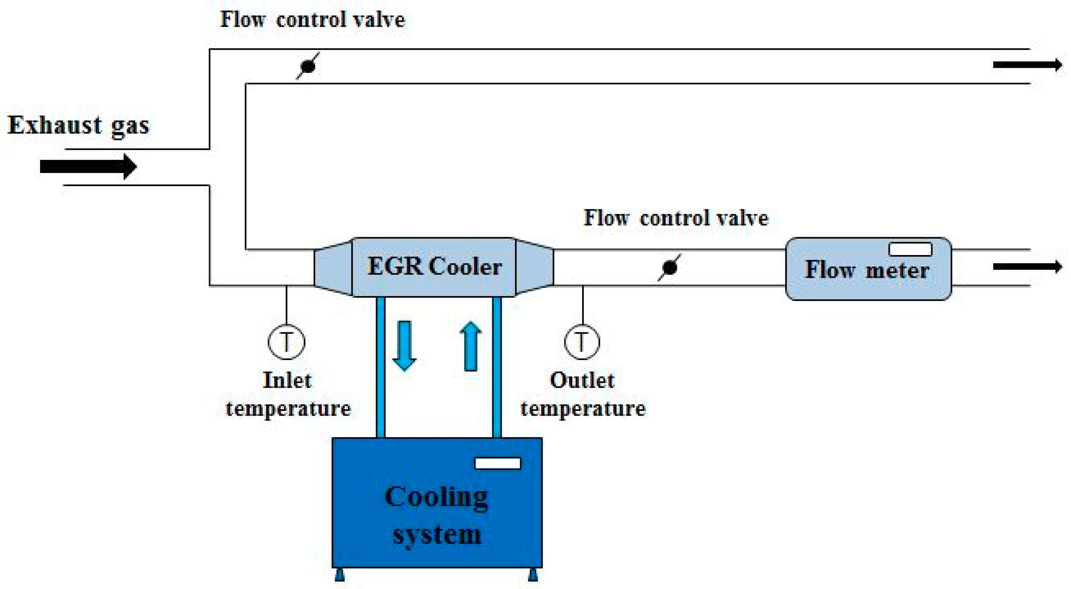
Engine-bench experiments using exhaust partial flow were conducted to study the effects of the variables (coolant temperature and flow rate) and DOC catalyst on EGR cooler fouling. Figure 2 shows a schematic diagram of the experimental system, which consists of five parts: (1) diesel engine; (2) EGR cooler fouling test-section; (3) flow control valve; (4) flow meter; and (5) cooling system. For the EGR cooler fouling test-section, a commercial EGR cooler with Euro 4 type was used, as specified in Table 1.
Using K-type thermocouples, the temperature was measured in real-time at the front and rear of the EGR cooler and transmitted to a data acquisition board (Data Translation, model DT-9805) connected to a computer. The equation for the heat transfer efficiency is presented below:
where ε is the effectiveness of the EGR cooler, Tgas,in is the temperature of the inlet EGR gas, Tgas,out is the temperature of the outlet EGR gas, and Tcoolant,in is the temperature of the inlet coolant.
- Flow control valve: In this experiment, the pipe of the exhaust gas was altered to allow by-pass in order to evaluate the EGR cooler fouling phenomenon using the exhaust partial flow from the engine. Flow control valves were installed in each pipe to control the flow rate. These valves could be used by connecting the compressor.
- Flow meter: A flow meter was set up at the rear of the cooler to measure the flow rate of the gas passing the test section. This device measured the flow rate by passing a current signal of 4–20 mA to the data acquisition board within the flow rate range of 1.5–150 g s−1.
- Cooling system: A device for controlling the temperature of the coolant entering the EGR cooler was set up separately to evaluate the effect of the coolant temperature on EGR cooler fouling. In the engine-bench experiment, it was difficult to maintain the temperature of the coolant entering the EGR cooler, unlike the case of the laboratory experiment, because in the former, exhaust gases pass the test section at high temperature and a high flow rate. Therefore, a radiator and fan were installed to maintain a constant coolant temperature.
Equation (2) shows the relation between the thermophoretic force and parameters. Where T is the absolute temperature of the EGR gas, p is the pressure of the EGR gas, λ is the mean free path, is the particle diameter, and is the temperature gradient. The negative sign represents the force direction accompanying the temperature decrease.
2.3. Experimental Conditions
For the laboratory experiment, it was easy to separate the variables. However, this setup is ineffective for replicating the engine exhaust gas. Therefore, the engine-based experimental data were compared with the results of the laboratory experiments.
Prior to the experiment for evaluating the effects of the variables, basic evaluation of the EGR cooler fouling was performed under various engine conditions. Thus, severe fouling phenomena could be investigated at an engine speed of 2000 rpm and brake mean effective pressure (BMEP) of 6 bar. Thus, to visually confirm the effect of the variables on EGR cooler fouling, the selected engine conditions were as follows: engine speed: 2000 rpm and BMEP of 6 bar. The engine specifications are presented in Table 2.
The other conditions are as follows: coolant temperatures of 80 °C and 60 °C were chosen; the flow rate was calculated as 20% of the EGR rate based on the maximum flow rate of the exhaust gas; 10% of the EGR rate was chosen to evaluate the effect of the flow rate on EGR cooler fouling.
The temperature of the coolant and exhaust gas were maintained constant by warming up the engine for 20−30 min before the experiments; the effectiveness of the EGR cooler was measured over 5 h.
3. Results and Discussion
3.1. Effect of Coolant Temperature, Flow Rate and DOC Catalyst in the Lab-Scale Test
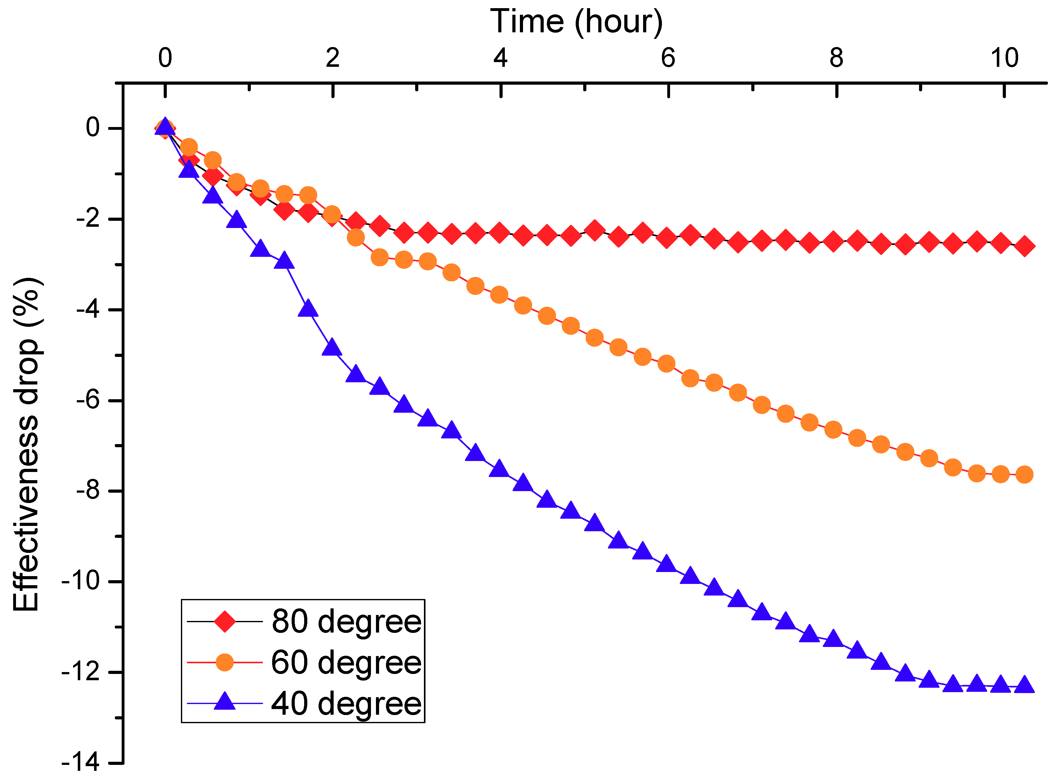
In previous research, a laboratory experiment was conducted by using a PM generator to evaluate the effects of the coolant temperature, flow rate, and DOC catalyst on EGR cooler fouling. All experiments were performed for 10 h. The experiment was carried out at various coolant temperatures (80 °C, 60 °C, and 40 °C). The other conditions were as follows: the EGR inlet gas temperature was 350 °C, the mean particle size was 128 nm, and the flow rate was 4 sLPM.
Figure 3 shows the fundamental effects of the coolant temperature on the decline in the effectiveness of the EGR cooler with time in the lab-scale test. It also shows that the decline in the effectiveness of the EGR cooler was more pronounced as the coolant temperature decreased due to the stronger thermophoretic force, as indicated in Equation (2). After 10 h, the cooler performance declined by 1.7% at 80 °C, 5% at 60 °C, and 7% at 40 °C. The drop in the effectiveness of the cooler reached saturation at different times with variation of the coolant temperature. Under higher coolant temperature conditions, deposits formed five times faster than at lower coolant temperatures, where the drop in the effectiveness was less.
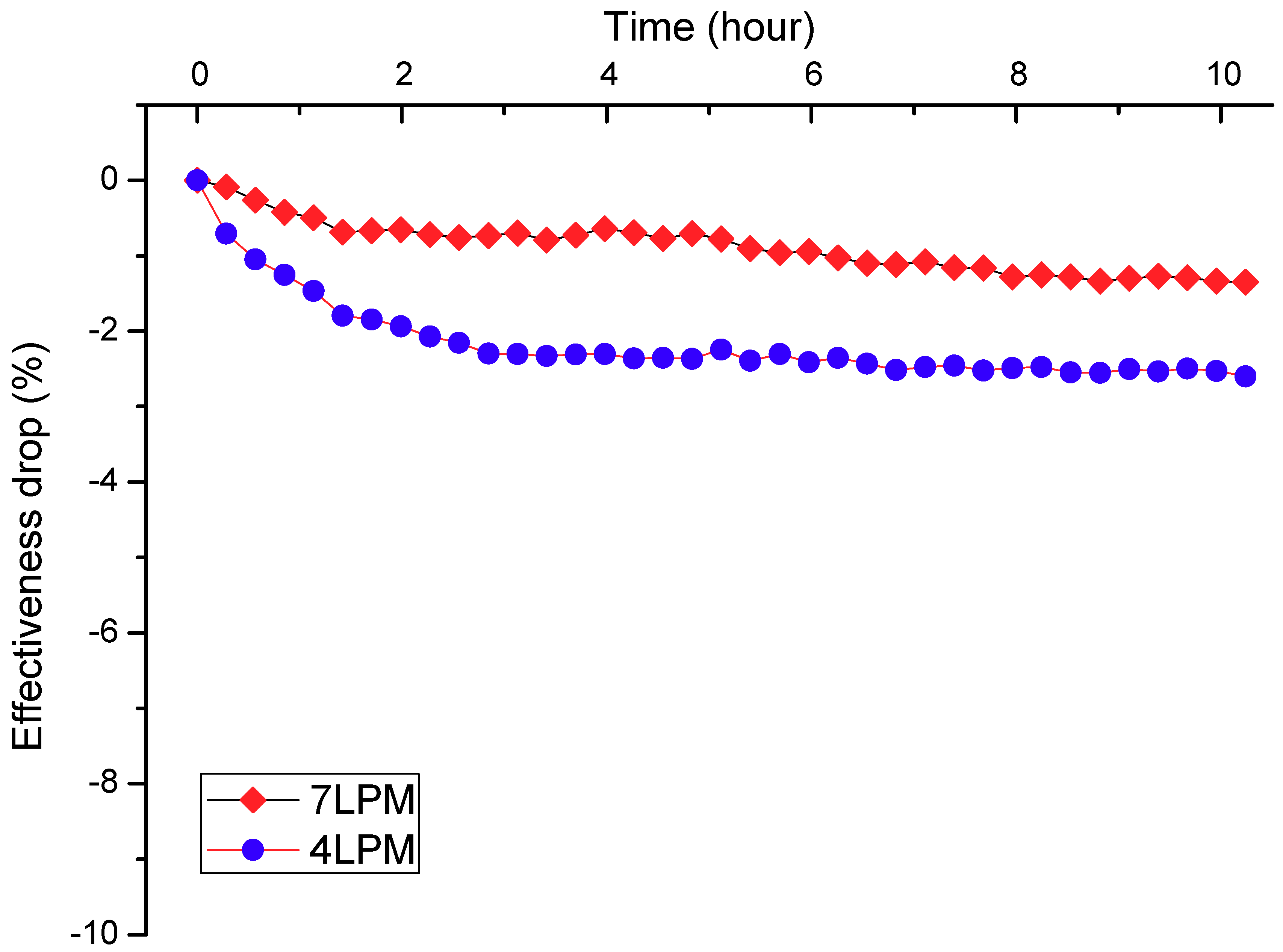
The experiment was also carried out with variations in the flow rate. Herein, low flow rates of 4 sLPM and 7 sLPM where severe fouling is known to occur, were selected. The other conditions were as follows: EGR inlet gas temperature: 350 °C, mean particle size: 128 nm, and coolant temperature: 80 °C. As shown in Figure 4, the increase in the flow rate led to a less pronounced decline in the effectiveness of the EGR cooler. After 10 h, the degradation of the cooler performance was 1.7% at 4 sLPM and 0.4% at 7 sLPM.
Referring to our previous research, the effect of the DOC catalyst on EGR cooler fouling was evaluated. In this experiment, the DOC catalyst was loaded with platinum at two different concentrations of 5 g/ft3 and 30 g/ft3, and the DOC catalyst was set up upstream of the EGR cooler. The results show that the drop in the effectiveness of the EGR cooler was small with high contents of Pt. When the EGR inlet gas temperature was set to 480 °C, similar to the temperature of the exhaust gas, the effectiveness declined by 13% without the DOC catalyst and by 10% with the DOC catalyst at a loading of Pt 30 g/ft3. However, this is disadvantageous in that the initial effectiveness of the EGR cooler with the DOC catalyst was lower than that without the DOC catalyst due to the exothermic reaction of the DOC catalyst [15].
3.2. Effect of Coolant Temperature, Flow Rate and DOC Catalyst in the Engine-Bench Test
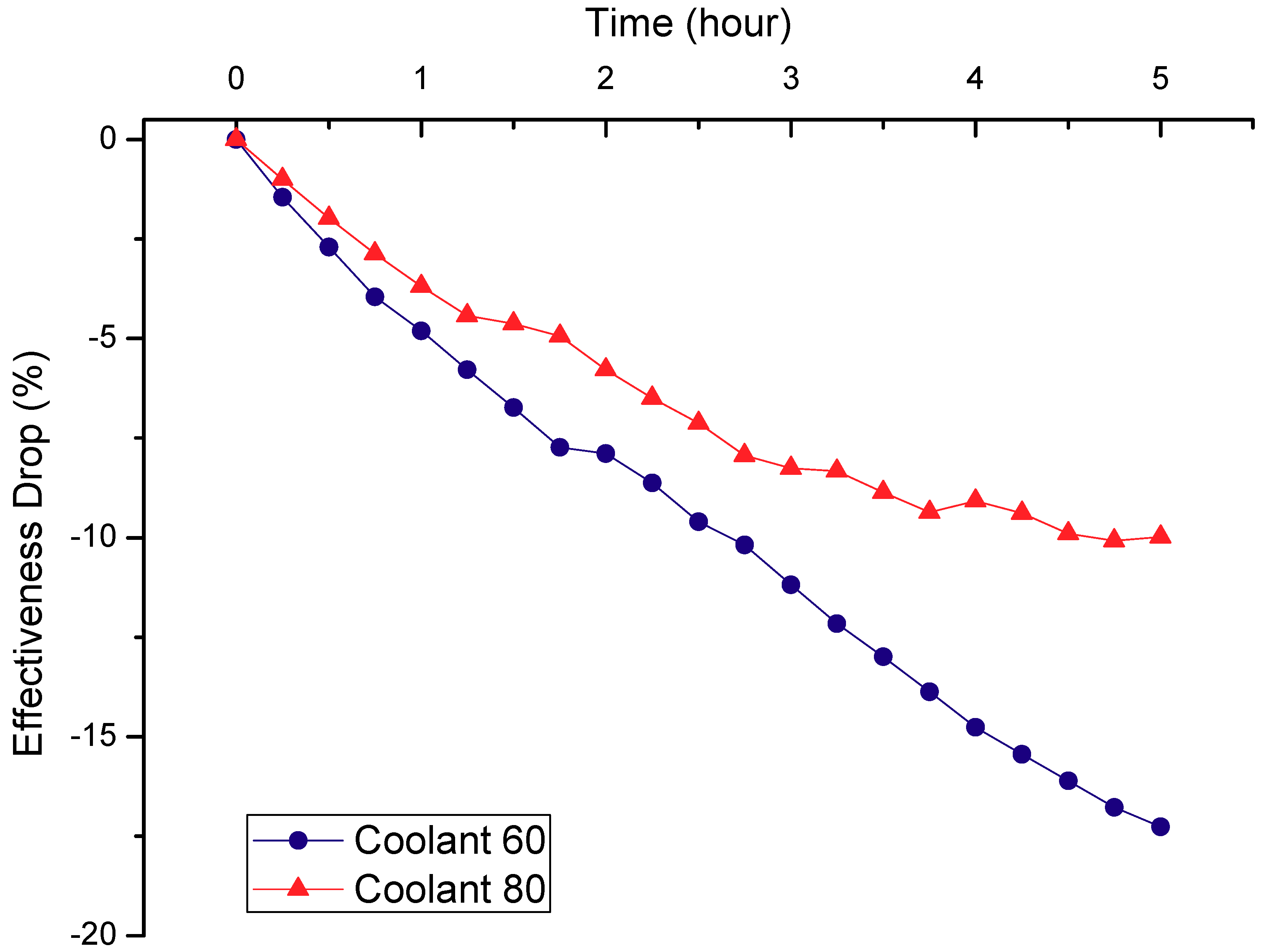
An experiment was conducted to evaluate the decline in the effectiveness of the EGR cooler at different coolant temperatures of 60 °C and 80 °C. The other conditions were as follows: engine speed: 2000 rpm, BMEP: 6 bar, flow rate: 1.8 g·s−1, and EGR inlet gas temperature: 420 °C.
Figure 5 shows that lowering the coolant temperature caused a more pronounced drop in the effectiveness of the EGR cooler. The performance of the EGR cooler decreased by about 17% at a coolant temperature of 60 °C and 10% at a coolant temperature of 80 °C compared with the initial performance.
This result is attributed to the fouling mechanism. The fouling mechanisms are generally known as thermophoresis and diffusion by condensation. In thermophoresis, the gas molecule moves under a thermal gradient field. In detail, the gas molecules that affect the particles on the hot side move faster than those on the colder side. Thus, a net force is generated, causing the particles to move. The particles that move to the wall of the cooler are condensed. These condensations induce a local concentration gradient in the cooler. The other mechanism is diffusion by condensation. Diffusion involves movement of the particle by a concentration gradient.
From the results of this study, the effects of the fouling mechanism were elucidated. When the coolant temperature is lower, the thermophoretic force may be stronger because the temperature gradient and diffusion also actively increases. Consequently, the EGR cooler fouling phenomenon may be caused by lower coolant temperatures. This result is very similar to that of the laboratory experiment.
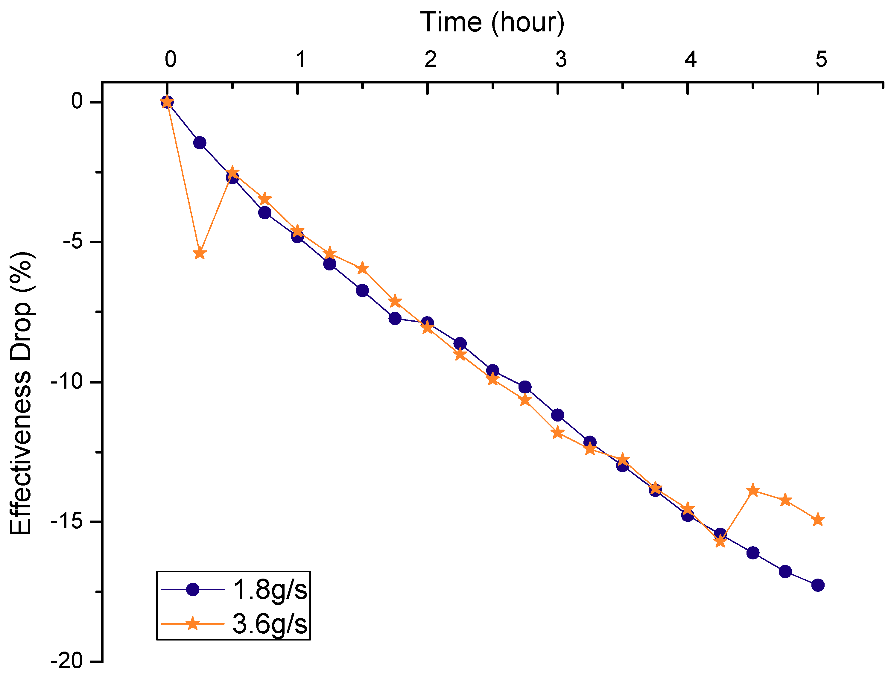
An experiment was conducted to evaluate the decline in the effectiveness of the EGR cooler at different flow rates of 1.8 g s−1 and 3.6 g s−1. The other conditions were as follows: engine speed: 2000 rpm, BMEP: 6 bar, coolant temperature: 60 °C, EGR inlet gas temperature: 420 °C.
Figure 6 shows that there was slight variation in the effectiveness of the EGR cooler with variation of the coolant temperature. This is not consistent with the observed worsening of the fouling phenomenon as the flow rate decreased in the laboratory experiment.
This result is plausibly due to the difference in the experimental conditions of the laboratory and engine-bench tests. In the laboratory experiment, the particle number and size were equally controlled by the soot generator. The carrier gas must be changed in order to control the flow rate. If the flow rates increases, there is no change in the numbers of particles in the exhaust gas, but the momentum of the particle increases. Therefore, the amount of soot deposited on the wall diminished because the thermophoretic force became stronger.
However, if the flow rate increases, the number of particles should increase correspondingly in the engine-bench experiment. Thus, no effects of the flow rate were found.
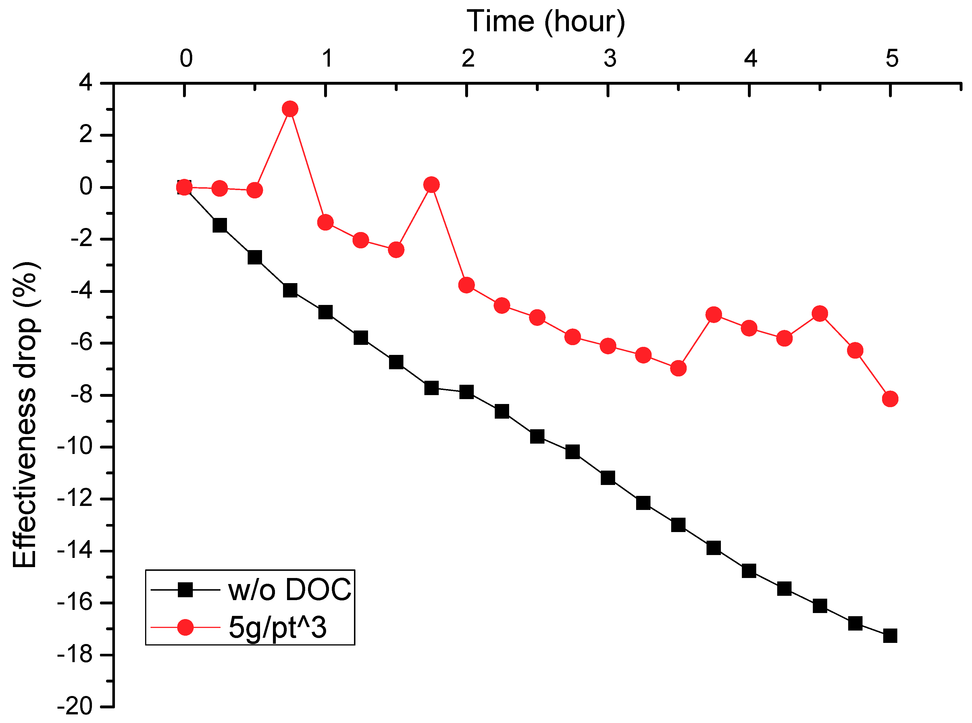
In order to evaluate the effects of the DOC catalyst, an experiment was conducted in which the DOC catalyst was set up upstream of the EGR cooler. The engine conditions were as follows: engine speed: 2000 rpm, BMEP: 6 bar, flow rate: 1.8 g s−1, coolant temperature: 60 °C, and platinum loading: 5 g/ft3.
Figure 7 shows that the performance of the EGR cooler with the DOC catalyst was about 9% better than that without the DOC catalyst. It is thus implicit that the soluble organic fraction (SOF) of the PM can be partially removed by passing through the DOC. A reduction of the SOF in the PM with the DOC catalyst was found in previous research in the lab-scale test [15]. As a result, the effects of the DOC catalyst were stronger under the engine operating conditions, which provides evidence that the optimized catalyst is very important in the real engine-bench test.
4. Conclusions
The purpose of this study was to evaluate the effects of the coolant temperature, flow rate, and DOC catalyst on the drop in the effectiveness of the EGR cooler in an engine-bench experiment. The results were compared with that of the laboratory experiment. Engine experiments were performed with a light-duty diesel engine to control the independent variables. The conclusions are as follows:
- The drop in the effectiveness of the EGR cooler was more pronounced when the coolant temperature was lower in both the laboratory and engine-bench experiments. This result proves that the fouling phenomenon was severe due to the temperature difference between the exhaust gas and wall of the cooler.
- In the lab-scale test, the effectiveness of the cooler declined to a greater extent at low flow rate than at high flow rate. This is attributed to the increase in the momentum of the particles for a constant number of particles. On the other hand, there was no effect of the flow rate in the engine-bench experiment, as the particle number increases when the flow rate of the exhaust gas increases. This suggests that the effects of increasing the flow rate and particle number could be de-coupled from each other in a real engine environment.
- In the engine-bench test, the heat exchange performance with the DOC catalyst upstream of the cooler was improved by about 9% due to the reduction in the soluble organic fraction of the PM after passing through the DOC. The results show that the DOC catalyst may be effective for improving the performance of the EGR cooler.
Author Contributions
All authors have equally contributed.
Funding
This research was funded by Chosun University, 2017.
Acknowledgments
This research was supported by Chosun University, 2017.
Conflicts of Interest
The authors declare no conflict of interest.
Nomenclature
| BMEP | Brake mean effective pressure |
| CO | Carbon monoxide |
| CO2 | Carbon dioxide |
| DOC | Diesel oxidation catalytic converter |
| EGR | Exhaust gas recirculation |
| NOx | Nitric oxides |
| PM | Particulate matter |
| Pt | Platinum |
| THC | Total hydrocarbon |
References
- Walsh, M.P. Global trends in diesel emissions control. SAE Pap. 1997, 970179. [Google Scholar]
- Wade, W.R. Light-duty diesel NOx-HC-particulate trade-off studies. SAE Pap. 1980, 800335. [Google Scholar] [CrossRef]
- Zheng, M.; Reader, G.T.; Hawley, J.G. Diesel engine exhaust gas recirculation—A review on advanced and novel concepts. Energy Convers. Manag. 2004, 1145, 883–900. [Google Scholar] [CrossRef]
- Abd-Alla, G.H. Using exhaust gas recirculation in internal combustion engines: A review. Energy Convers. Manag. 2002, 43, 1027–1042. [Google Scholar] [CrossRef]
- Hoard, J.; Abarham, M.; Styles, D.; Giuliano, J.M.; Sluder, C.S.; Storey, J.M.E. Diesel EGR cooler fouling. SAE Int. J. Engines 2008, 1, 1234–1250. [Google Scholar] [CrossRef]
- Zhang, F.; Nieuwstadt, M. Adaptive EGR cooler pressure drop estimation. SAE Tech. Pap. 2008. [Google Scholar] [CrossRef]
- Maing, S.; Lee, K.S.; Song, S.; Chun, K.M.; Oh, B. Simulation of the EGR cooler fouling effect on NOx emission of a light duty diesel engine. Fall Conf. Proc. Korean Soc. Automot. Eng. 2007, 1, 214–220. [Google Scholar]
- Lance, M.J.; Sluder, C.S.; Wang, H.; Storey, J.M.E. Direct measurement of EGR cooler deposit thermal properties for improved understanding of cooler fouling. SAE Tech. Pap. 2009. [Google Scholar] [CrossRef]
- Grillot, J.M.; Icart, G. Fouling of a cylindrical probe and a finned tube bundle in a diesel exhaust environment. Exp. Therm. Fluid Sci 1997, 14, 442–457. [Google Scholar] [CrossRef]
- Bravo, Y.; Moreno, F.; Longo, O. Improved characterization of fouling in cooled EGR system. SAE Tech. Pap. 2007. [Google Scholar] [CrossRef]
- Usui., S.; Ito, K.; Kato, K. The effect of semi-circular micro riblets on the deposition of diesel exhaust particulate. SAE Tech. Pap. 2004. [Google Scholar] [CrossRef]
- Charles, F.L.R.; Ewing, D.; Becard, J.; Chang, J.S.; Cotton, J.S. Optimization of the exhaust mass flow rate and coolant temperature for exhaust gas recirculation (EGR) cooling devices used in diesel engines. SAE Tech. Pap. 2005. [Google Scholar] [CrossRef]
- Ismail, B.; Charles, F.; Ewing, D.; Cotton, J.S.; Chang, J.S. Mitigation of the diesel soot deposition effect on the exhaust gas recirculation (EGR) cooling devices for diesel engines. SAE Tech. Pap. 2005. [Google Scholar] [CrossRef]
- Bravo, Y.; Lazaro, J.L.; Garcia-Bernad, J.L. Study of fouling phenomena on EGR coolers due to soot deposits: Development of a representative test method. SAE Tech. Pap. 2005. [Google Scholar] [CrossRef]
- Hong, K.S.; Park, J.; Lee, K.S. Evaluation of catalyst assisted EGR cooler system for EGR cooler fouling reduction. Trans. KSAE 2011, 19, 76–81. [Google Scholar]
Figure 1.
Schematic diagram of laboratory experimental system.
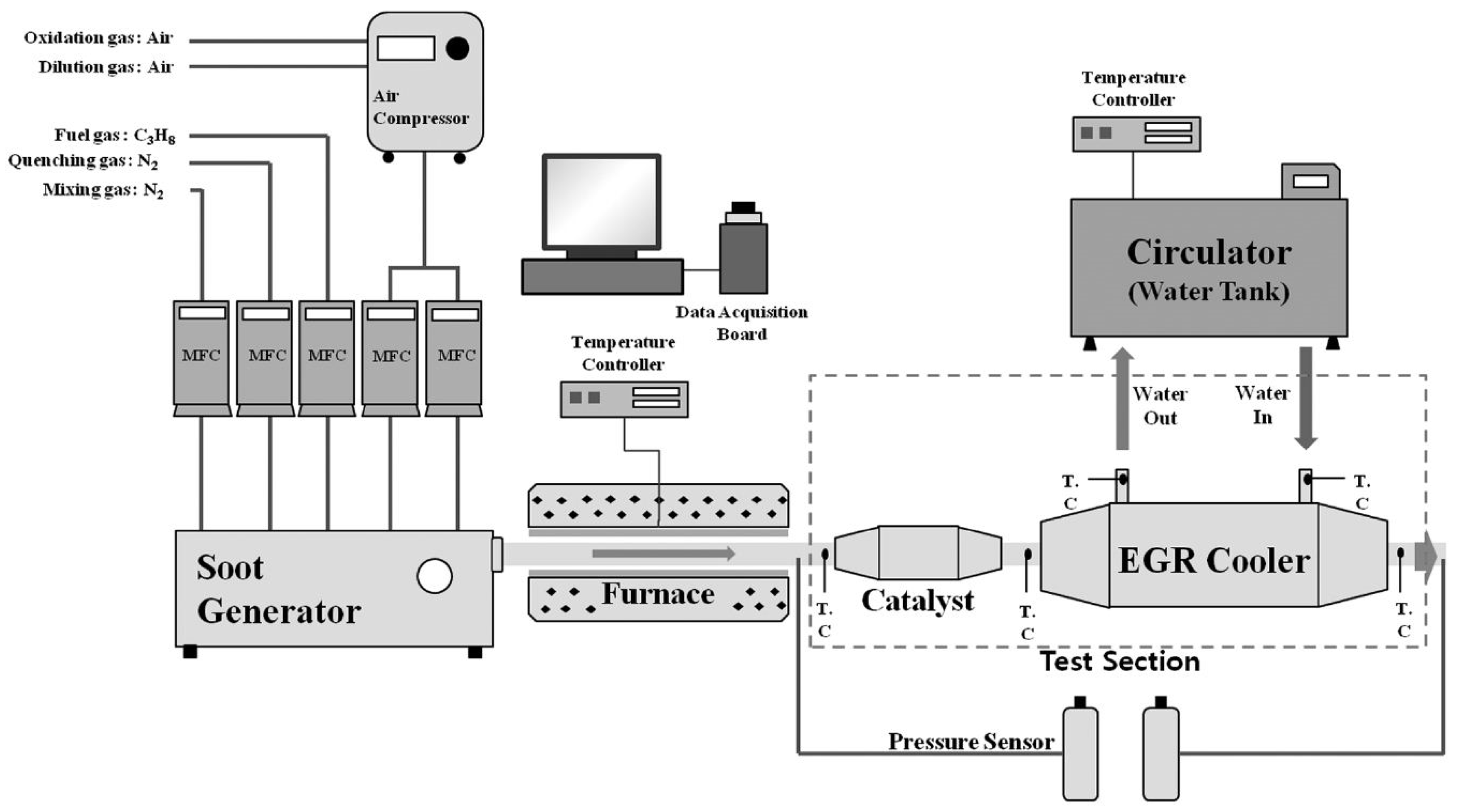
Figure 2.
Schematic diagram of engine-bench experimental system.

Figure 3.
Decline in effectiveness over course of 10 h with respect to various coolant temperatures. EGR inlet gas temperature: 450 °C, mean particle size: 128 nm, and EGR gas flow rate: 4 sLPM.
Figure 3.
Decline in effectiveness over course of 10 h with respect to various coolant temperatures. EGR inlet gas temperature: 450 °C, mean particle size: 128 nm, and EGR gas flow rate: 4 sLPM.

Figure 4.
Effectiveness drop over the course of 10 h with variation in the flow rate. EGR inlet gas temperature: 450 °C, mean particle size: 128 nm, and coolant temperature: 80 °C.
Figure 4.
Effectiveness drop over the course of 10 h with variation in the flow rate. EGR inlet gas temperature: 450 °C, mean particle size: 128 nm, and coolant temperature: 80 °C.

Figure 5.
Effectiveness drop over the course of 5 h with respect to different coolant temperatures. Engine speed: 2000 rpm, BMEP: 6 bar, flow rate: 1.8 g s−1, EGR inlet gas temperature: 420 °C.
Figure 5.
Effectiveness drop over the course of 5 h with respect to different coolant temperatures. Engine speed: 2000 rpm, BMEP: 6 bar, flow rate: 1.8 g s−1, EGR inlet gas temperature: 420 °C.

Figure 6.
Decline in effectiveness over the course of 5 h with respect to different flow rates. Engine speed: 2000 rpm, BMEP: 6 bar, coolant temperature: 60 °C, and EGR inlet gas temperature: 420 °C.
Figure 6.
Decline in effectiveness over the course of 5 h with respect to different flow rates. Engine speed: 2000 rpm, BMEP: 6 bar, coolant temperature: 60 °C, and EGR inlet gas temperature: 420 °C.

Figure 7.
Decline in effectiveness over the course of 5 h with respect to DOC catalyst. Engine speed: 2000 rpm, BMEP: 6 bar, flow rate: 1.8 g s−1, coolant temperature: 60 °C, and EGR inlet gas temperature: 420 °C.
Figure 7.
Decline in effectiveness over the course of 5 h with respect to DOC catalyst. Engine speed: 2000 rpm, BMEP: 6 bar, flow rate: 1.8 g s−1, coolant temperature: 60 °C, and EGR inlet gas temperature: 420 °C.


Table 1.
Specifications for single-channel exhaust gas recirculation (EGR) cooler.
| Length (mm) | 350 |
| Inner diameter (mm) | 11.7 |
| Outer diameter (mm) | 12.7 |
| Thickness (mm) | 0.5 |
| Spiral | Non-spiral type |
| Material | ASTM 304 |
Table 2.
Engine specifications.
| Engine Type | Four Cylinders |
|---|---|
| Fuel-injection system | Common rail diesel |
| Bore × stroke | 83 mm × 92 mm |
| Displacement | 1991 cc |
| Maximum torque | 32.7 kgf·m/2000 rpm |
| Maximum power | 150 PS/4000 rpm |
| Compression ratio | 17.5 |
© 2018 by the authors. Licensee MDPI, Basel, Switzerland. This article is an open access article distributed under the terms and conditions of the Creative Commons Attribution (CC BY) license (http://creativecommons.org/licenses/by/4.0/).
Share and Cite
MDPI and ACS Style
Park, S.; Lee, K.S.; Park, J. Parametric Study on EGR Cooler Fouling Mechanism Using Model Gas and Light-Duty Diesel Engine Exhaust Gas. Energies 2018, 11, 3161. https://doi.org/10.3390/en11113161
AMA Style
Park S, Lee KS, Park J. Parametric Study on EGR Cooler Fouling Mechanism Using Model Gas and Light-Duty Diesel Engine Exhaust Gas. Energies. 2018; 11(11):3161. https://doi.org/10.3390/en11113161
Chicago/Turabian StylePark, Sangjun, Kyo Seung Lee, and Jungsoo Park. 2018. "Parametric Study on EGR Cooler Fouling Mechanism Using Model Gas and Light-Duty Diesel Engine Exhaust Gas" Energies 11, no. 11: 3161. https://doi.org/10.3390/en11113161
Note that from the first issue of 2016, this journal uses article numbers instead of page numbers. See further details here.