Experimental Study on the Performance of a Crashworthy Device for the Monopile Offshore Wind Turbine against Ship Impact


1
Deepwater Engineering Research Center, Dalian University of Technology, Dalian 116024, China
2
State Key Laboratory of Coast and Offshore Engineering, Dalian University of Technology, Dalian 116024, China
3
Offshore Wind Power R&D Center, Powerchina Huadong Engineering Corporation, Hangzhou 310014, China
*
Author to whom correspondence should be addressed.
Energies 2018, 11(11), 3173; https://doi.org/10.3390/en11113173
Submission received: 26 September 2018
/
Revised: 9 November 2018
/
Accepted: 13 November 2018
/
Published: 15 November 2018
(This article belongs to the Special Issue Recent Advances in Offshore Wind Technology)
Abstract
:In the present work, a crashworthy device for a monopile offshore wind turbine has been proposed, which consists of the inner two-layer rubber torus and the outer thin steel shell. The performance of the crashworthy device against ship impact has been investigated experimentally. Based on the prototype of a 4 MW monopile wind turbine in the East China Sea, the scale ratio of the test model has been designed to be 1/50. The test ship model has been simplified as a “rigid car” equipped with a high-frequency force sensor in the front, which is available for changing the ship mass with different weights. The ship-impact velocity can be accurately controlled by a motion platform driven by a direct current machine. The effect of the key design parameters of the crashworthy device on its anti-impact performance has been tested and compared under typical ship impact cases. The results indicate that the crashworthy device can effectively reduce both the ship impact force and the top nacelle acceleration, and the physical mechanism that has been clarified. The outer thin steel shell can significantly use its structural deformation to absorb the ship impact energy, which is beneficial for reducing the structural damage of the offshore wind turbine (OWT)’s tower. The inner rubber torus can effectively prolong the ship impact duration, which is available for smoothing the impact force. Finally, the porous design for the outer steel shell of the crashworthy device has been proposed and tested.
1. Introduction
Offshore wind energy, as one of the most promising renewable energies, has been paid more and more attention due to its own special advantages [1] (compared with onshore wind farms). Many countries (especially in Europe) have accumulated some technical and operational experience with offshore wind farms. In China, a large number of offshore wind farms have been built or will be established in the East China Sea. As the scale of the offshore wind farm extends, the risk of impact between ships and offshore wind turbine (OWT) structures will increase [2]. The offshore wind turbine is a typical kind of towering structure with a heavy “head”, so the severe dynamic response of the top structure is easily caused by ship impacts. Consequently, the large deformation of the impacted OWT tower may result in the overall instability of the whole OWT structure, which would be catastrophic. Some researchers pointed out the importance of the study on the ship-OWT impact and proposed a few precautionary measures for avoiding the impact of ships and OWTs [3,4,5]. Although some design suggestions for the ship-OWT impact can be found in several international standards (such as IEC 61400-3 [6], DNV-OS-J101 [7], etc.), the complicated high nonlinear problem is usually solved by a simplified quasi-static approach, which can hardly clarify the physical mechanism of the ship-OWT impact.
The foundation is the root of the OWT, so it is very important for the safety of the whole structure system. As for the foundation type of the OWT system, it mainly depends on the water depth and the seabed condition. For deeper water (usually larger than 60 m), the floating foundation type OWT is promising for practical projects, such as the spar, the tension leg platform (TLP), and the semi-submersible types. For shallow water, the fixed bottom foundation type is more cost-effective, such as monopile, tripod, gravity, and so on. The monopile is the most widely used foundation type for offshore wind farms in near-shore shallow water. However, the anti-impact performance of the monopile foundation is much lower than other foundation types (jacket or tripod) due to its lower horizontal stiffness, so it would be more dangerous in the case of ship impacts [8]. Nonlinear finite element method (FEM) numerical simulations of the ship–OWT impacts have been carried out, and the effects of wind loads, the ship deformability, and the soil flexibility on the dynamic responses of the impacted structure have been investigated [9]. A new conceptual steel sphere shell and aluminum foam ring pad crashworthy device for the monopile OWT has been proposed to minimize the damage of OWTs caused by ship impacts, and the good anti-impact performance of the device has been verified based on LS-DYNA code [10,11]. A kind of pneumatic structure has been proposed for the OWT structure against ship impact, and numerical simulations of anti-performance of the crashworthy device have been conducted based on ABAQUS code. It indicates that the pneumatic structure can effectively mitigate the dynamic responses of both the ship and the OWT structures [12]. A rubber blanket-outer steel shell crashworthy device has been proposed, the main parameters of which have been optimized by comparing the impact-force and nacelle acceleration based on the LS-DYNA explicit code [13,14]. The dynamic process of the OWT with a large-scale pre-stressing bucket foundation impacted by a ship has been simulated using ABAQUS/Explicit, and it indicates that most of the kinetic energy is transformed into the plastic dissipation and absorbed by the bucket foundation [15]. One kind of rubber fender crashworthy device has been proposed for the tripod OWT-ship impact, and the numerical results indicate that the rubber fender can effectively reduce the impact damage of the OWT [16]. For the jacket foundation, the dynamic responses of the ship-OWT impact have been numerically investigated, and factors affecting the structural damage caused by ship-OWT impact have been pointed out [17,18]. In addition, the effect of the steel structure on absorbing the impact energy (by using its plastic deformation) has been studied based on the nonlinear FEM models [19]. So far, experimental studies on both ship-OWT impacts and the anti-impact performance of related crashworthy devices have been very limited.
In this work, a crashworthy device for the monopile offshore wind turbine against ship impacts has been proposed, which consists of the inner rubber torus and the outer thin steel shell. The anti-impact performance of the crashworthy device has been investigated experimentally, based on the prototype of a 4MW monopile wind turbine in the East China Sea. The effect of the key design parameters of the crashworthy device on its anti-impact performance has been investigated and compared under typical ship impact cases. In addition, the porous design for the outer steel shell of the crashworthy device has been proposed and tested.
2. Project Background
The prototype offshore wind farm is located in the East China Sea, which is designed by POWERCHINA HUADONG ENGINEERING CORPORATION with the monopile foundation type. The maintenance ships and potential passing vessels are normally less than 2000 tons, considering the maximum water depth (only 15 m).
3. Ship-OWT Impact Model Test Setup
3.1. Overview of the Ship-OWT Impact System
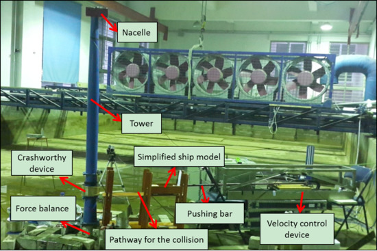
The scale model tests of the ship-OWT impact system have been done in the State Key Laboratory of Coastal and Offshore Engineering (SLCOE) at Dalian University of Technology. Comprehensively considering conditions of the laboratory (wave tank) and the size of full-scale 4 MW monopile OWT structure system, the scale ratio of the test model has been designed to be 1/50. The similarities of both the geometry and dynamic responses of the scale test model have been taken into consideration. The influence of scale (1/50) on the internal mechanics to the fracture propagation process has not been considered here, but it will be investigated by comparing the test date with more detailed full-scale numerical results. The overview of the ship-OWT impact test system with installed sensors and auxiliary devices is shown in Figure 1. Considering the simulation of the monopile-soil interaction is too complex for the scale test model, the monopile foundation of the OWT is simplified as a bottom-fixed boundary condition at the mud line. Therefore, the damping effect of the soil has been ignored during the model test of the ship-OWT impact. There is a high-frequency force balance (with a sensitivity of 0.001 N) at the bottom of the OWT, which is used for measuring six-DOF loads acting on the monopile. The scale test model is mainly made of steel, the main design parameters of which are listed in Table 1.
3.2. Simplified Ship Model
Different ships have different dimensions, and different ship shapes can greatly influence the impact results. Considering the main aim of this work is to investigate the anti-impact effect of a crashworthy device for the monopile OWT, this model test mainly focused on different ship impact energies (not a specific ship model). Then, the test ship model was simplified as a “rigid car” equipped with a high-frequency force sensor in the front (for the monitoring of the impact forces with the accuracy of 0.001 N). The ship model is flexible for the simulation of ships with different mass by putting different mass blocks (in Figure 2). The impact end (with a certain circle area) of the equipped force sensor is good for the future numerical simulation comparison with an accurate impact location/area. The added mass effect of the ship model due to the surrounding water has been taken into consideration by the factor of 0.1 for the front impact according to the DNV-OS-A101 Standard [20].
The simplified car model can be driven and controlled by a direct current machine platform through a rigid steel pushing bar (in Figure 1). The direct current machine can accurately simulate different constant speed motions, or even other complex programmed motions (with the accuracy of 0.001 m/s), and has flexibility regarding the simulation of different ship impact velocities. By the way, the car model can automatically separate from the pushing bar before the car impacts the OWT (with the fixed distance of 0.01 m in the tests).
The ship impact location on the tower is controlled by an assistant pathway device (in Figure 1), which is flexible for adjusting different ship impact locations. The ship model can move along the lubricated pathway device with neglectable friction effect according to the monitoring data from the calibrated laser displacement sensor (with the accuracy of 0.0001 m).
3.3. Crashworthy Device
Considering the plastic strain on the key structure is usually not allowed in the serviceability limit state for marine structures, it is necessary to propose a crashworthy device for both the structural safety and the normal operation of offshore wind turbines after ship impacts. Therefore, a conceptual crashworthy device is proposed for the monopile OWT, which consists of the two-layer inner rubber torus and the outer thin steel shell (in Figure 3). The inner rubber torus and the outer steel shell are both easily replaceable with different thickness ones. The gap design between the two rubber layers is available for using the deformation of the outer steel shell to absorb the ship impact energy (in Figure 2), as well as beneficial for reducing the rubber cost. The impacted part of the tower of the test model (near “the water line”) is replaceable, which is flexible for the installation of the crashworthy device in the model tests. In addition, the crashworthy device is installed on the impacted part of the tower, with the consideration of the water depth of 15 m. In the model test, the lower edge of the crashworthy device is about −1 m and the upper edge of the crashworthy device is about 4 m. For practical use, the position of the crashworthy device can be further optimized by considering the possible impact ship’s dimensions and the corresponding tower structure.
4. Results and Discussion
To make sure the data sampling is synchronized, the direct current machine, the impact force sensor, the nacelle accelerometer, and the force balance sensor have been all set to record data at the same time with the same sample frequency of 1000 Hz during model tests. To minimize the potential uncertainties and errors from the model tests, every test case has been repeated at least three times. A large amount of experimental data indicates that the effects of measurement uncertainties and random errors are not significant in the model tests. In addition, all sensors have been calibrated before doing model tests, and their performance has also been well tested in other model tests [21]. All results are presented in full-scale for ease of understanding (with no additional specification).
4.1. Effect of Different Rubber Radial Thicknesses of the Crashworthy Device
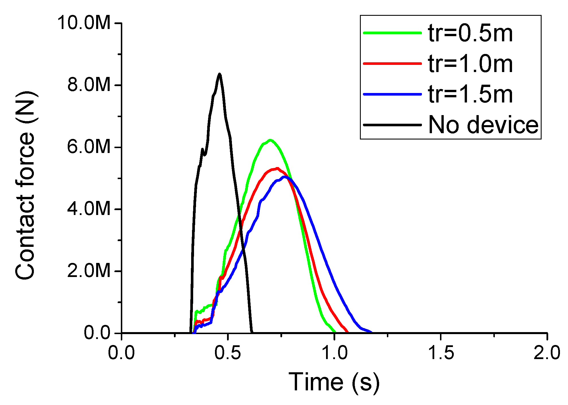
To investigate the effect of different rubber radial thicknesses on the anti-impact performance of the crashworthy device, the thickness of the outer steel shell of the device is chosen as 5 mm. The ship mass and velocity during the ship-OWT front impact (according to the suggestion of the DNV-OS-J101 standard) are set to be 2000 t and 1 m/s, respectively. The impact force time histories for different rubber radial thickness (tr) crashworthy devices have been compared and shown in Figure 4. From Figure 4, it can be seen that the proposed crashworthy device can significantly reduce the peak value of the impact force, compared with the results without the device. This is because the crashworthy device can effectively prolong the impact duration (to about two times than that of the no-device case), as well as smooth the impact force. As the rubber radial thickness increases from 0.5 m to 1.5 m, the peak value of the impact force gradually decreases, while the impact duration increases. More comparison results of main OWT dynamic responses for different rubber radial thickness devices have been shown in Table 2.
In Table 2, it can be seen that the impact force, the top nacelle acceleration, and the monopile bending moment (at the mud line) can be all effectively reduced by the crashworthy device, especially for the nacelle acceleration. The nacelle acceleration can strongly influence the operational performance and reliability of the wind turbine generator system located at the top nacelle, as well as causing considerable inertial force on the tower due to its large mass (about 250 t). Similar to the trend of the impact force comparison (in Figure 4), the nacelle acceleration and the monopile bending moment both gradually decrease as the rubber radial thickness increases. However, when the rubber radial thickness increases from 1.0 m to 1.5 m, the anti-performance (on the reduction effect of the main OWT dynamic responses) between the two cases are not significantly improved. Therefore, the rubber radial thickness of the crashworthy device is preliminary suggested to be 1.0 m in the cost-effective view.
4.2. Effect of Different Steel Shell Thickness of the Crashworthy Device
To investigate the effect of different steel shell thicknesses on the anti-impact performance of the crashworthy device, the inner rubber radial thickness of the device is chosen as 1.0 m. The ship mass and velocity during the ship-OWT front impact are also set to be 2000 t and 1 m/s, respectively. The impact force time histories for different steel shell thickness (ts) crashworthy devices have been compared and shown in Figure 5. On the contrary of the comparison results in Figure 4, as the steel shell thickness increases from 5 mm to 10 mm, the peak value of the impact force gradually increases, while the impact duration decreases. This is because the thicker steel shell is much harder for its deformation, which is not beneficial for using its plastic deformation to absorb the ship impact energy. As a result, the peak value of the impact force slightly increases due to the shorter duration of the impact energy absorption. More comparison results of main OWT dynamic responses for different steel shell thickness devices have been shown in Table 3.
In Table 3, it can be seen that the nacelle acceleration and the monopile bending moment both gradually increase as the steel shell thickness increases, which is similar to the trend of the impact force results (in Figure 5). However, the outer steel shell of the crashworthy device should not be too thin to stand with the corrosion effect due to the serious offshore environment, as well as the potential larger impact energy. Therefore, the thickness of the steel shell is an important parameter, which needs optimization to balance both the economy and anti-impact performance according to the specific ship impact energy and environmental corrosion effect. In the present study, the steel shell thickness of the crashworthy device is preliminarily suggested to be 5 mm for the following model tests.
4.3. Effect of Different Impact Energy
To investigate the anti-impact performance of the crashworthy device under typical ship impact energies, the inner rubber radial thickness and the outer steel shell thickness are chosen as 1.0 m and 5 mm, respectively. Comparison results of main OWT dynamic responses under different ship impact energies have been shown in Table 4.
It indicates that the crashworthy device can effectively reduce responses of the impact force, the nacelle acceleration, and the monopile bending moment under all impact cases, especially for the low impact speed cases (V = 1 m/s). Under the same ship impact energy cases (such as case 2 and case 3), the main OWT dynamic responses of two cases with no device are very similar, while the anti-impact performance of the same crashworthy device on the main OWT dynamic responses is obviously different. The crashworthy device’s performance on the reduction effects of the impact force, the nacelle acceleration, and the monopile bending moment under case 3 is much better than that of case 2, with almost the same ship impact energy. This is because the lower impact velocity better allows the crashworthy device to prolong the impact duration, so more time can be used for the plastic deformation of its outer steel shell to absorb impact energy. Therefore, it is strongly suggested that the velocity of maintenance ships or other potential passing ships should be as low as possible when accessing offshore wind farms. It is very beneficial for avoiding significant structural damage of both the OWT and the ship in the risk of ship-OWT impact, as well as for good anti-impact performance of the crashworthy device.
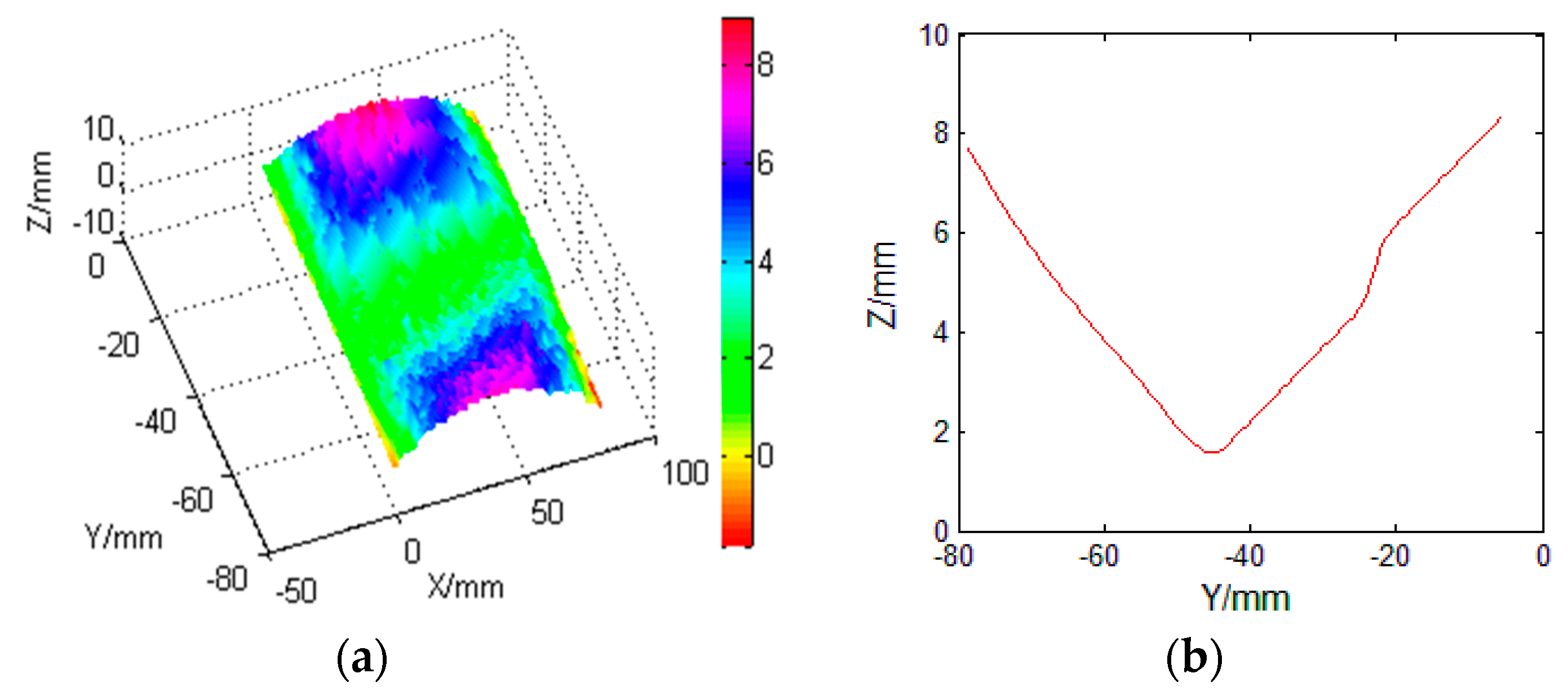
In addition, the stereovision 3D measurement system is used for the investigation of the surface deformation of the outer steel shell of the crashworthy device under the case 2, which is integrated based on MATLAB (R2016a) code (by comparing the high-resolution structural photos of before and after the collision). The availability and the accuracy of the stereovision 3D measurement system have been verified by corresponding studies [22]. The surface deformation information of the outer steel shell is shown in Figure 6 (with the scale ratio of 1/50). From Figure 6a, it can be seen that there is an obvious 3D hollow in the middle of the outer steel shell of the crashworthy device after the ship impact. This indicates that the outer steel shell of the crashworthy device can effectively use its plastic deformation to absorb the impact energy. Figure 6b can quantitively describe the maximum hollow depth (about 7 mm) in the 2D view. Considering the maximum hollow depth of the outer steel shell is much smaller than the inner rubber radial thickness (20 mm), there is almost no plastic deformation on the tower of the OWT due to there being no directive contact between the ship and the OWT structure. This reflects the design idea of sacrificing the plastic deformation of the unimportant attachment structure (such as the crashworthy device) to protect the OWT main structure.
4.4. Effect of the Porous Design for the Outer Steel Shell
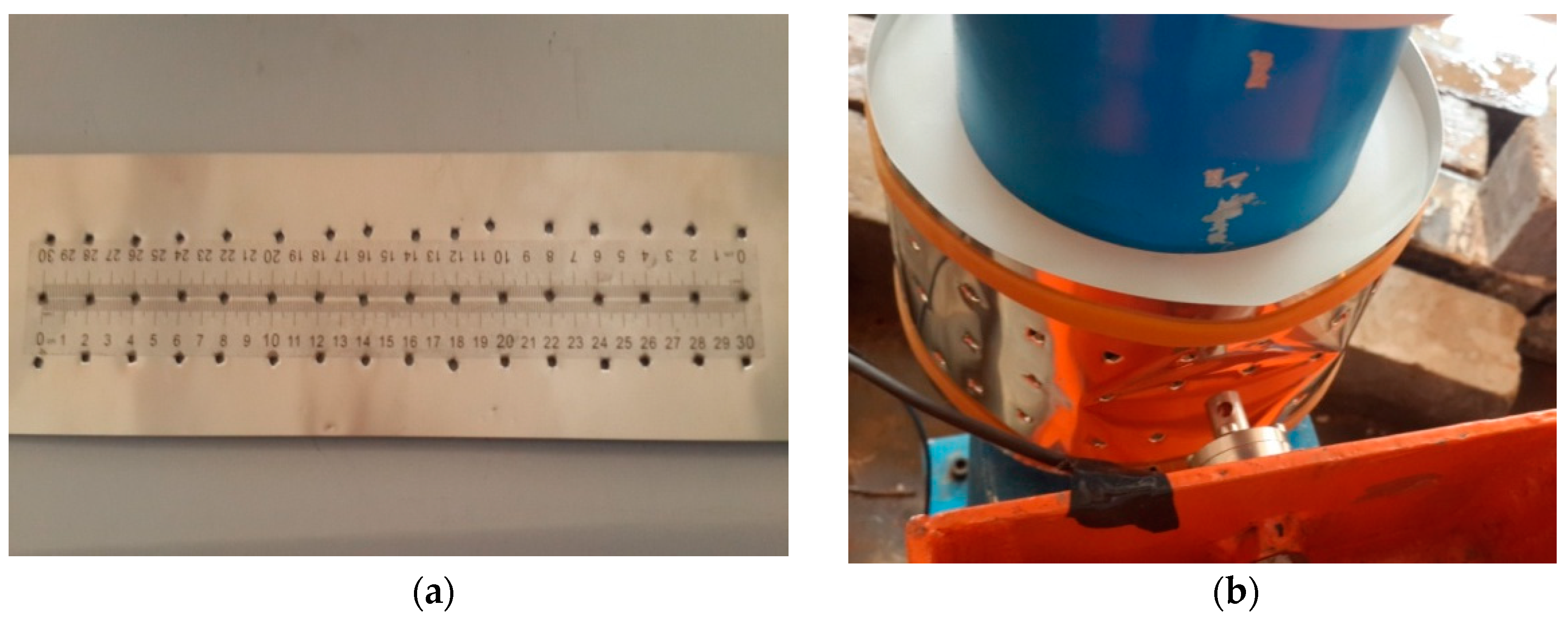
For better using the plastic deformation of the outer steel shell to absorb the ship-OWT impact energy, the surface porous design for the outer steel shell of the crashworthy device has been proposed, and the anti-impact performance of the porous design crashworthy device under typical ship impact cases has been further investigated. The diameter and the interval of each hole are initially designed as 0.25 m and 1.0 m (in Figure 7a), respectively. Comparison results of main OWT dynamic responses under typical ship impact cases have been shown in Table 5.
From Table 5, it can be observed that the crashworthy device with the porous design can effectively reduce more dynamic responses of both impact force and nacelle acceleration, compared with those of no porous design. Therefore, the porous design with proper corrosion prevention may be better for improving the anti-impact performance of the crashworthy device, as well as reducing both the cost of the steel material and the wave loads acting on the crashworthy device.
5. Conclusions
In this work, a crashworthy device for the monopile offshore wind turbine has been proposed, which consists of the inner rubber torus and the outer thin steel shell. The anti-impact performance of the crashworthy device under typical ship-OWT impact cases has been investigated and verified experimentally. The main results can be summarized as follows.
The proposed crashworthy device can significantly reduce the impact force, the nacelle acceleration, and the monopile bending moment of the OWT due to effectively prolonging the impact duration, compared with the results without the device. The gap design between the two inner rubber layers is very helpful for using the deformation of the outer steel shell to absorb the ship impact energy, as well as being beneficial for reducing the rubber cost. The rubber torus can effectively smooth the ship impact force acting on the OWT tower. There is almost no plastic deformation on the tower of the OWT due to no directive contact between the ship and the OWT. It clearly reflects the design idea of sacrificing the plastic deformation of the unimportant crashworthy device to protect the OWT main structure.
The anti-impact performance of the crashworthy device becomes better with the increase of the rubber radial thickness, while it tends to become worse with the increase of the outer steel shell thickness. The preliminarily optimal values for both the rubber radial thickness and the outer steel shell thickness have been suggested in the cost-effective view.
For the same ship impact energy cases, lower impact velocity is better for the crashworthy device to prolong the impact duration, which is beneficial for using its plastic deformation to absorb impact energy. It is strongly suggested that the velocity of maintenance ships or other potential passing ships should be as low as possible when accessing offshore wind farms.
The porous design of the outer steel shell is good for improving the anti-impact performance of the crashworthy device, as well as reducing the cost of the steel material. In addition, a comparison between the model test data and corresponding numerical results with the consideration of the monopile-soil interaction effect will be performed in later work.
6. Future Work
Many challenges related to the feasibility of the new crashworthy device still remain, and the development of a robust concept for actual deployment requires further investigation. Challenges will include the effect of the scale (1/50) on the dynamic response and internal mechanics to the fracture propagation process, the corrosion of the outside steel shell on the anti-impact performance of the device, the optimal design of the device, and the comparison/validation with numerical models for more detailed information. A study of these aspects should be included in the future research, especially for developing the numerical model.
Author Contributions
Main contribution (model tests and data analysis), N.R. and Z.M.; Field data and project information, W.L.; Supervision and comments, J.O.; Comments and suggestions, D.N.
Funding
This research was supported by the National Natural Science Foundation of China (Grant Nos. 51709040, 51761135011, 51709118), the Fundamental Research Funds for the Central Universities. The financial supports are greatly acknowledged.
Conflicts of Interest
The authors declare no conflict of interest.
References
- Su, X. The statistics and analysis of the global offshore wind power development in 2012. Wind Energy 2013, 6, 30–35. [Google Scholar]
- Dai, L.; Ehlers, S.; Rausand, M.; Utne, I.B. Risk of collision between service vessels and offshore wind turbines. Reliab. Eng. Syst. Saf. 2013, 109, 18–31. [Google Scholar] [CrossRef]
- Biehl, F. Ship collisions and offshore wind energy turbines: Calculation and Evaluation. In Proceedings of the Scientific Forum of the Federal Ministry for the Environment, Nature Conservation and Nuclear Safety (BMU) on Offshore Wind Energy, Utilisation, Berlin, Germany, 15–18 June 2004. [Google Scholar]
- Kremser, E. Risk assessment and precautionary measures for offshore wind parks. In Proceedings of the Scientific Forum of the Federal Ministry for the Environment, Nature Conservation and Nuclear Safety (BMU) on Offshore Wind Energy, Utilisation, Berlin, Germany, 15–18 June 2004. [Google Scholar]
- Bontempi, F.; Li, H.; Petrini, F.; Manenti, S. Numerical modeling for the analysis and design of offshore wind turbines. In Proceedings of the 4th International Conference on Advances in Structural Engineering and Mechanics (ASEM’08), Jeju, Korea, 26–28 May 2008. [Google Scholar]
- International Electrotechnical Commission. IEC 61400-3 Wind Turbines—Part 3: Design Requirements for Offshore Wind Turbines; IEC: Geneva, Switzerland, 2009. [Google Scholar]
- Det Norske Veritas. DNV-OS-J101 Offshore Standard. Design of Offshore Wind Turbine Structures; Det Norske Veritas: Oslo, Norway, 2014. [Google Scholar]
- Hao, E.T.; Liu, C.G. Evaluation and comparison of anti-impact performance to offshore wind turbine foundations: Monopile, tripod, and jacket. Ocean Eng. 2017, 130, 218–227. [Google Scholar] [CrossRef]
- Bela, A.; Sourne, H.L.; Buldgen, L.; Tigo, P. Ship collision analysis on offshore wind turbine monopile foundations. Mar. Struct. 2017, 51, 220–241. [Google Scholar] [CrossRef]
- Ren, N.X.; Ou, J.P. Dynamic numerical simulation for ship-OWT collision. In Proceedings of the 8th International Conference on Reliability, Maintainability and Safety, Chengdu, China, 20–24 July 2009; pp. 1003–1007. [Google Scholar]
- Ren, N.X.; Ou, J.P. A crashworthy device against ship–OWT collision and its protection effects on the tower of offshore wind farms. China Ocean Eng. 2009, 23, 593–602. [Google Scholar]
- Graczykowski, C.; Holnicki-Szulc, J. Protecting offshore wind turbines against ship impacts by means of adaptive inflatable structures. Shock Vib. 2009, 16, 335–353. [Google Scholar] [CrossRef]
- Hao, E.T.; Liu, Y.Z.; Liu, C.G. Numerical simulation of monopile foundation of an offshore wind turbine subjected to ship impact. J. Vib. Shock 2015, 3, 7–13. [Google Scholar]
- Liu, C.G.; Hao, E.T.; Zhang, S.B. Optimization and application of a crashworthy device for the monopile offshore wind turbine against ship impact. Appl. Ocean Res. 2015, 51, 129–137. [Google Scholar] [CrossRef]
- Ding, H.Y.; Zhu, Q.; Zhang, P.Y. Dynamic simulation on collision between ship and offshore wind turbine. Trans. Tianjin Univ. 2014, 20, 1–6. [Google Scholar] [CrossRef]
- Lee, K. Effects on the various rubber fenders of a tripod offshore wind turbine substructure collision strength due to boat. Ocean Eng. 2013, 72, 188–194. [Google Scholar] [CrossRef]
- Zhang, J.H.; Gao, D.W.; Sun, K.; Zhang, Z. Ship impact behavior on jacket type offshore wind turbine foundation. In Proceedings of the 33rd International Conference on Ocean, Offshore and Arctic Engineering, San Francisco, CA, USA, 8–13 June 2014. [Google Scholar]
- Moulas, D.; Shafiee, M.; Mehmanparast, A. Damage analysis of ship collisions with offshore wind turbine foundations. Ocean Eng. 2017, 143, 149–162. [Google Scholar] [CrossRef]
- Lehmann, E.; Peschmann, J. Energy absorption by the steel structure of ships in the event of collisions. Mar. Struct. 2002, 15, 429–441. [Google Scholar] [CrossRef]
- Det Norske Veritas. Offshore Standard DNV-OS-A101, Safety Principals and Arrangements; Det Norske Veritas: Oslo, Norway, 2013. [Google Scholar]
- Ren, N.X.; Ma, Z.; Fan, T.H.; Zhai, G.J.; Ou, J.P. Experimental and numerical study of hydrodynamic responses of a new combined monopile wind turbine and a heave-type wave energy converter under typical operational conditions. Ocean Eng. 2018, 159, 1–8. [Google Scholar] [CrossRef]
- Shan, B.H.; Zheng, S.J.; Ou, J.P. A stereovision-based crack width detection approach for concrete surface assessment. KSCE J. Civ. Eng. 2016, 20, 803–812. [Google Scholar] [CrossRef]
Figure 1.
Overview of the ship-OWT impact test system.

Figure 2.
The local close-up of the ship-OWT impact with a crashworthy device.

Figure 3.
Detailed description of the crashworthy device. (a) Inner rubber torus; (b) Outer thin steel shell.
Figure 3.
Detailed description of the crashworthy device. (a) Inner rubber torus; (b) Outer thin steel shell.
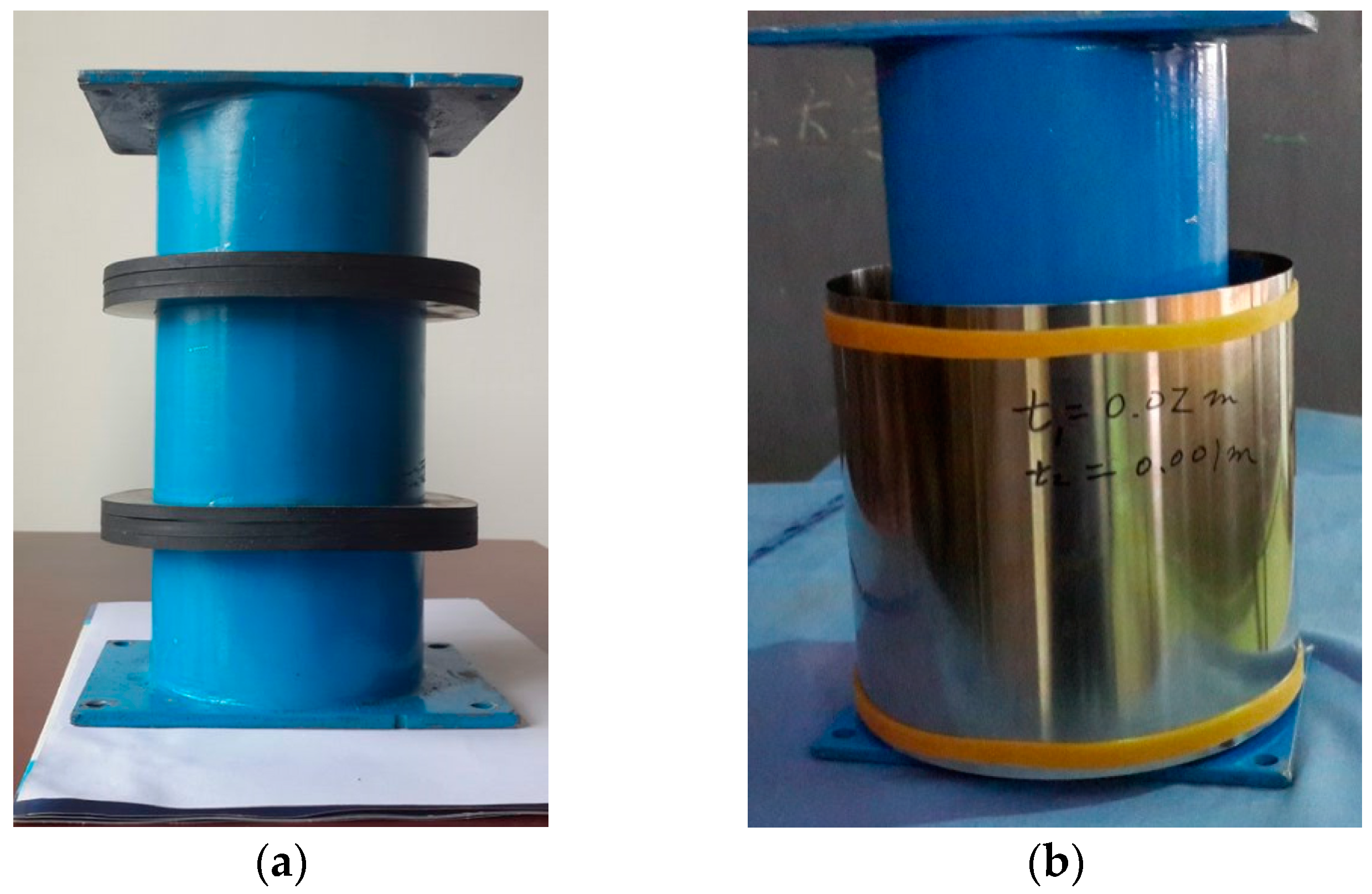
Figure 4.
Comparison of the impact force for different rubber thickness devices.

Figure 5.
Comparison of the impact force for different steel shell thickness devices.
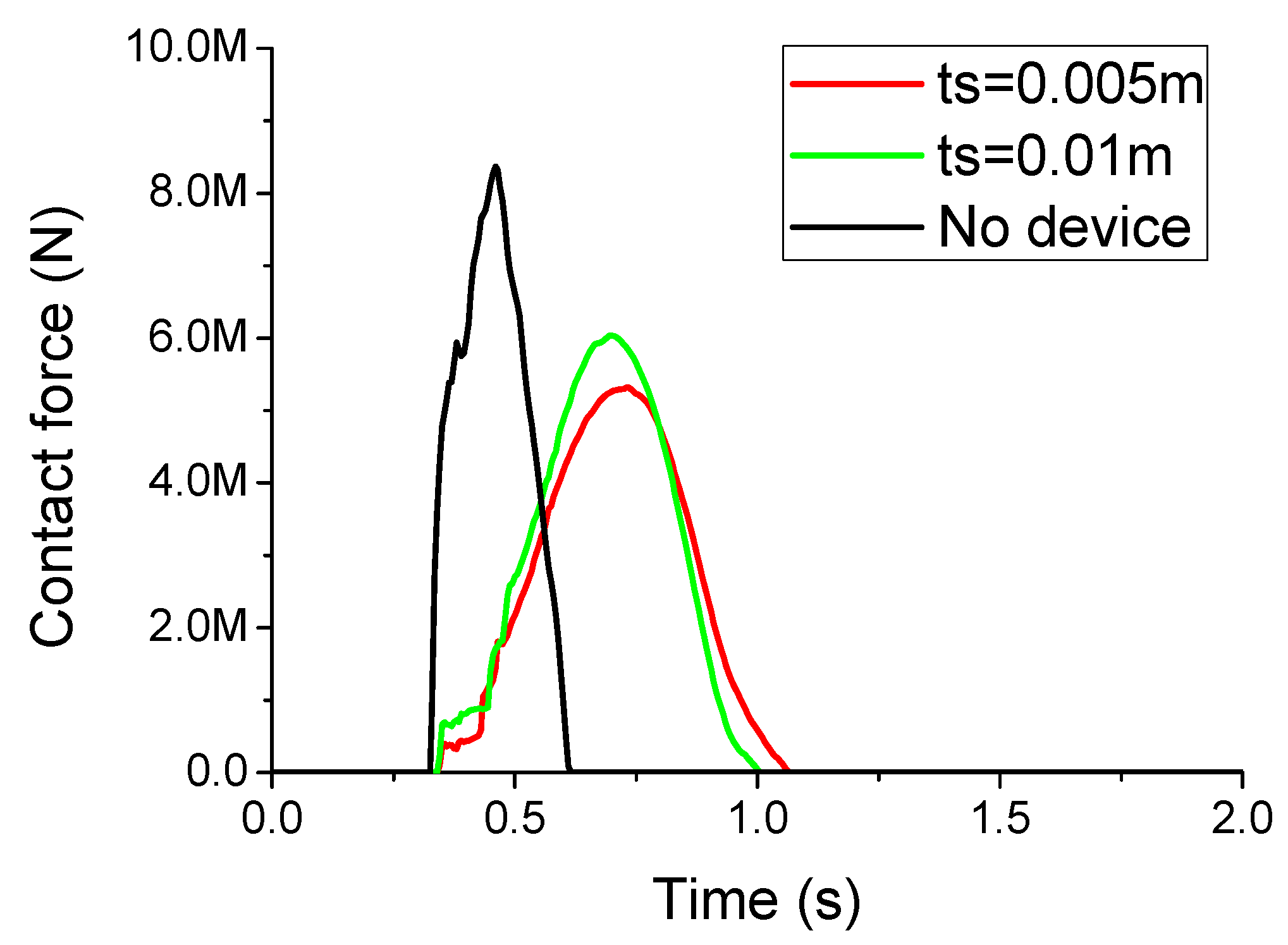
Figure 6.
Deformation information of the steel shell of the crashworthy device (for the case 2). (a) Three-dimensional information; (b) Two-dimensional information near the impact zone.
Figure 6.
Deformation information of the steel shell of the crashworthy device (for the case 2). (a) Three-dimensional information; (b) Two-dimensional information near the impact zone.

Figure 7.
Crashworthy device with porous shell model tests. (a) A sample of the porous steel shell; (b) Crashworthy device with the porous shell.
Figure 7.
Crashworthy device with porous shell model tests. (a) A sample of the porous steel shell; (b) Crashworthy device with the porous shell.


Table 1.
Main design parameters of the ship-OWT impact model.
| Parameters | Full Model | Scale Model (1:50) |
|---|---|---|
| Wind turbine | 4 MW | ------ |
| Water depth (m) | 15 | 0.3 |
| Nacelle and blades (kg) | 250,000 | 2.0 |
| Tower height (m) | 87.5 | 1.75 |
| Tower above MWL (m) | D1 = 3.5~5.5 t1 = 0.025~0.075 | D1 = 0.07~0.11 t1 = 0.0005~0.0015 |
| Tower below MWL (m) | D2 = 5.5~7.0 t2 = 0.075 | D2 = 0.11~0.14 t2 = 0.0015 |
| Ship model | ||
| Ship mass (kg) | 500,000~2,000,000 | 4~16 |
| impact velocity (m/s) | 1.0~2.0 | 0.14~0.28 |
| Crashworthy device | ||
| Rubber torus (m) | tr = 0.5~1.5; hr = 1.0 | tr = 0.01~0.03 hr = 0.02 |
| Steel shell (m) | ts = 0.005~0.010 hs = 5.0 | ts = 0.0001~0.0002 hs = 0.1 |
Table 2.
Comparison of main OWT dynamic responses for different rubber radial thickness devices.
| Crashworthy Device | tr (m) | Impact Force (MN) | Ratio * | Acceleration (m/s2) | Ratio * | Bending Moment (MNm) | Ratio * |
|---|---|---|---|---|---|---|---|
| No | ----- | 8.36 | 100% | 5.58 | 100% | 70.53 | 100% |
| Yes | 0.5 | 6.20 | 74% | 2.35 | 42% | 47.40 | 67% |
| Yes | 1.0 | 5.30 | 64% | 1.80 | 32% | 42.30 | 60% |
| Yes | 1.5 | 5.00 | 60% | 1.70 | 30% | 40.60 | 58% |
* Note: the ratio is calculated by the response with the device divided by that of no device.
Table 3.
Comparison of main OWT dynamic responses for different steel shell thickness devices.
| Crashworthy Device | ts (mm) | Impact Force (MN) | Ratio * | Acceleration (m/s2) | Ratio * | Bending Moment (MNm) | Ratio * |
|---|---|---|---|---|---|---|---|
| No | ----- | 8.36 | 100% | 5.58 | 100% | 70.53 | 100% |
| Yes | 5.0 | 5.35 | 64% | 1.80 | 32% | 42.30 | 60% |
| Yes | 10.0 | 6.00 | 72% | 2.00 | 36% | 47.40 | 67% |
* Note: the ratio is calculated by the response with the device divided by that of no device.
Table 4.
Comparison of main OWT dynamic responses for different impact energies.
| Case No. | Impact Information | Crashworthy Device | Impact F (MN) | Ratio * | Acceleration (m/s2) | Ratio * | Bending M (MNm) | Ratio * |
|---|---|---|---|---|---|---|---|---|
| 1 | 500 t | No | 5.82 | 100% | 5.31 | 100% | 38.85 | 100% |
| V = 1 m/s | Yes | 3.00 | 52% | 1.60 | 30% | 18.65 | 48% | |
| 2 | 500 t | No | 8.30 | 100% | 6.89 | 100% | 69.50 | 100% |
| V = 2 m/s | Yes | 6.65 | 80% | 3.15 | 46% | 51.70 | 74% | |
| 3 | 2000 t | No | 8.36 | 100% | 5.58 | 100% | 70.53 | 100% |
| V = 1 m/s | Yes | 5.30 | 64% | 1.80 | 32% | 42.30 | 60% | |
| 4 | 2000 t | No | 11.55 | 100% | 7.30 | 100% | 157.50 | 100% |
| V = 2 m/s | Yes | 10.40 | 90% | 3.05 | 42% | 135.45 | 86% |
* Note: the ratio is calculated by the response with the device divided by that of no device.
Table 5.
Comparison of main OWT dynamic responses with the porous design of the steel shell.
| Case No. | Impact Information | Device with Porous | Impact F (MN) | Ratio * | Acceleration (m/s2) | Ratio * |
|---|---|---|---|---|---|---|
| 1 | 500 t | No | 3.00 | 52% | 1.60 | 30% |
| V = 1 m/s | Yes | 2.80 | 48% | 1.40 | 26% | |
| 2 | 500 t | No | 6.67 | 80% | 2.64 | 38% |
| V = 2 m/s | Yes | 6.45 | 78% | 2.40 | 35% | |
| 4 | 2000 t | No | 10.40 | 90% | 3.05 | 42% |
| V = 2 m/s | Yes | 10.05 | 87% | 2.90 | 40% |
* Note: the ratio is calculated by the response with the device divided by that of no device.
© 2018 by the authors. Licensee MDPI, Basel, Switzerland. This article is an open access article distributed under the terms and conditions of the Creative Commons Attribution (CC BY) license (http://creativecommons.org/licenses/by/4.0/).
Share and Cite
MDPI and ACS Style
Ren, N.; Li, W.; Ma, Z.; Ou, J.; Ning, D. Experimental Study on the Performance of a Crashworthy Device for the Monopile Offshore Wind Turbine against Ship Impact. Energies 2018, 11, 3173. https://doi.org/10.3390/en11113173
AMA Style
Ren N, Li W, Ma Z, Ou J, Ning D. Experimental Study on the Performance of a Crashworthy Device for the Monopile Offshore Wind Turbine against Ship Impact. Energies. 2018; 11(11):3173. https://doi.org/10.3390/en11113173
Chicago/Turabian StyleRen, Nianxin, Wei Li, Zhe Ma, Jinping Ou, and Dezhi Ning. 2018. "Experimental Study on the Performance of a Crashworthy Device for the Monopile Offshore Wind Turbine against Ship Impact" Energies 11, no. 11: 3173. https://doi.org/10.3390/en11113173
Note that from the first issue of 2016, this journal uses article numbers instead of page numbers. See further details here.