Article

Experimental Investigation on Hydraulic Fracture Propagation of Carbonate Rocks under Different Fracturing Fluids

1
State Key Laboratory of Geomechanics and Geotechnical Engineering, Institute of Rock and Soil Mechanics, Chinese Academy of Sciences, Wuhan 430071, China
2
State Key Laboratory for Coal Mine Disaster Dynamics and Control, Chongqing University, Chongqing 400044, China
*
Author to whom correspondence should be addressed.
Energies 2018, 11(12), 3502; https://doi.org/10.3390/en11123502
Submission received: 9 November 2018 / Revised: 30 November 2018 / Accepted: 12 December 2018 / Published: 15 December 2018

Abstract

:
Deep carbonate reservoirs are rich in oil and gas resources. However, due to poor pore connectivity and low permeability, it is necessary to adopt hydraulic fracturing technology for their development. The mechanism of hydraulic fracturing for fracture initiation and propagation in carbonate rocks remains unclear, especially with regard to selection of the type of fracturing fluid and the fracturing parameters. In this article, an experimental study focusing on the mechanisms of hydraulic fracturing fracture initiation and propagation is discussed. Several factors were studied, including the type of injecting fracturing fluids, pump flow rate, fracturing pressure curve characteristics, and fracture morphology. The results showed the following: (1) The viscosity of fracturing fluid had a significant effect on fracturing breakdown pressure. Under the same pump flow rate, the fracturing breakdown pressure of slick water was the lowest. Fracturing fluids with low viscosity could easily activate weakly natural fractures or filled fractures, leading to open microcracks, and could effectively reduce the fracturing breakdown pressure. (2) The fluctuations in fracturing pump pressure corresponded with the acoustic emission hits and changes in radial strain; for every drop of fracturing pressure, acoustic emission hits and changes in radial strain were mutated. (3) Under the same fracturing fluid, the pump flow rate mainly affected fracturing breakdown pressure and had little effect on fracture morphology. (4) The width of the main fracture was affected by the viscosity and pump flow rate. Maximum changes in radial strain at the fracturing breakdown pressure point occurred when the fracturing fluid was guar gum. (5) With gelled acid and cross-linked acid fracturing, the main fractures were observed on the surface. The extension of the fracturing crack was mainly focused near the crack initiation parts. The crack expanded asymmetrically; the wormhole was dissolved to break through to the surface of the specimen. (6) The dissolution of gelled acid solution could increase the width of the fracturing crack and improve the conductivity of carbonate reservoirs.

1. Introduction

With the development of economy and society, demand for energy is increasing gradually. Oil and gas account for 56% of primary energy consumption. Carbonate reservoirs in ultra-deep wells contain abundant oil and gas resources, accounting for 60% of the proven oil and gas reserves in the world. The Ordovician carbonate reservoir in the northern part of Ordovician is the main oil production area in China. However, because the Ordovician carbonate reservoir in the Tarim Basin has extremely low permeability, most of the wells need to be stimulated. Presently, hydraulic fracturing is an important technology used to increase production, and it has been successfully applied to reservoirs with low permeability [1]. Although the hydraulic fracturing behavior of rocks has been studied by a large number of researchers, these have mainly focused on tight sandstone and shale [2].
Hydraulic fracturing experiment is a useful technical method to study the mechanism of fracture initiation and propagation. Many hydraulic fracturing experiments on coal, sandstone, artificial sample blocks, grained rocks, and shale have already been carried out [2,3,4,5,6,7,8,9,10,11]. The hydraulic fracturing mechanism of fractures in different rocks has been revealed, and the influence of natural fractures on hydraulic fracture propagation has been studied [12,13]. However, fractured carbonate rocks contain a large number of unopened natural fractures with strong heterogeneity. A large number of experimental studies have shown that carbonate rocks have unique physical and mechanical properties [14]. The effects of wettability of fracture surface, oil saturation of matrix, and injection fluid on fracture seepage have been previously studied [15], but studies relating to hydraulic fracturing experiments on carbonate rocks are very rare. Acidizing or acid fracturing is the most effective technology for increasing oil and gas production in carbonate reservoirs [16]. However, because of the existence of acid–rock reaction, the fracture propagation morphology of carbonate rock is distinct from other rock masses, and it is difficult to obtain accurate fracturing pump pressure characteristics and fracture morphology.
In view of the problems of existing technologies, we conducted an experimental study on hydraulic fracturing of carbonate rocks, focusing on the mechanisms of fracturing fracture initiation and propagation using different fracturing fluids in the laboratory scale. We studied the effect of different fracturing breakdown pressures, changes in radial strain, fracture morphology, and acoustic emission (AE) characteristics with different injection fracturing fluids and compared and analyzed the effects of fracturing fluids and pump flow rate on the complex fractures. The aim was to understand the main factors that affect the fracturing fracture initiation and propagation of fractured carbonate reservoirs.

2. Experimental Materials and Procedure

2.1. Sample Preparation
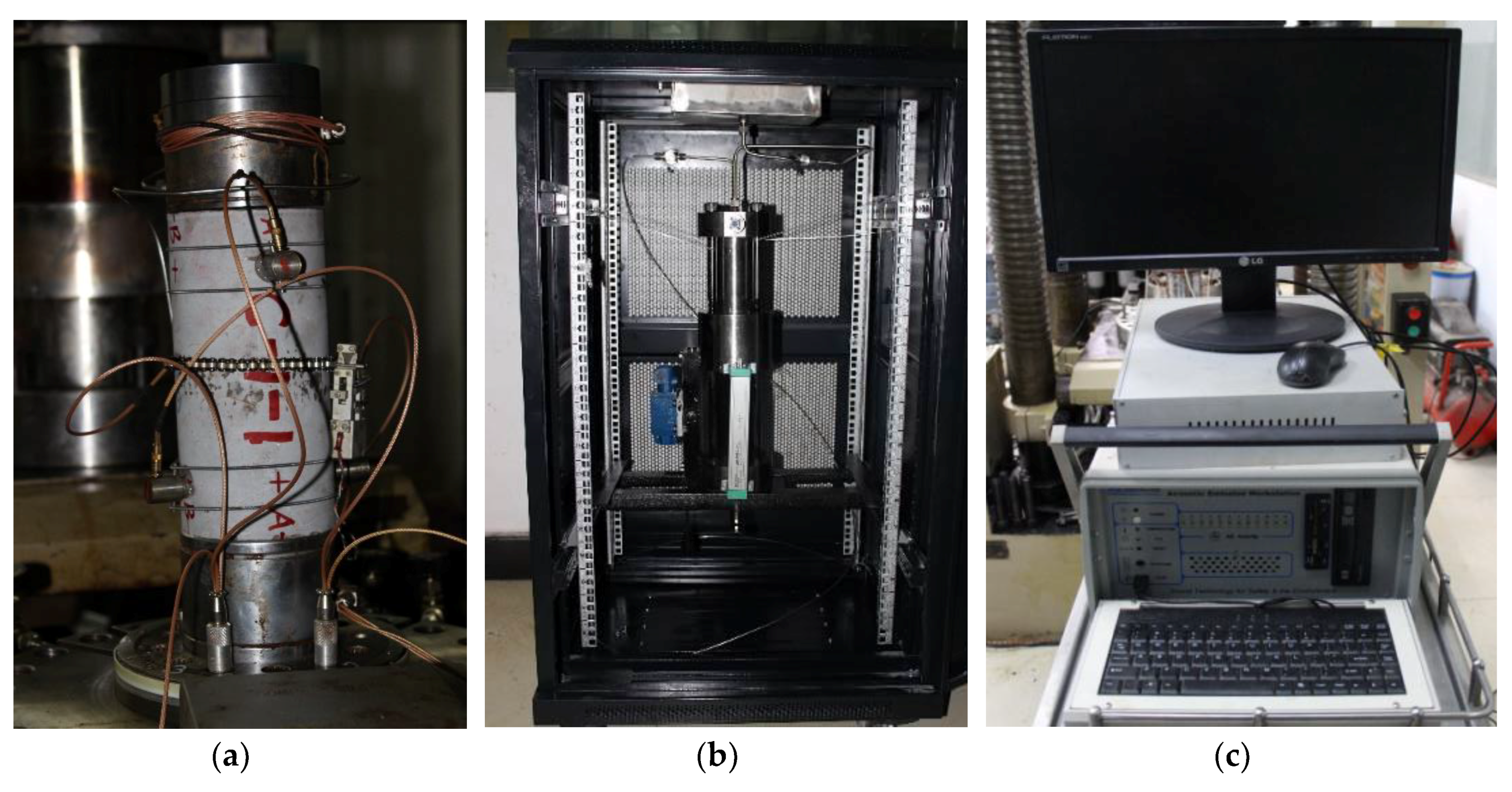
The Ordovician carbonate samples were obtained from the outcrops of Shunbei formation in Akesu County, Xinjiang province, China. The average mineral composition was 92.49% calcite, 4.98% iron dolomite, and 1.83% quartz. Some physical and mechanical properties of carbonate used in triaxial fracturing tests are shown in Table 1.
Test samples measuring 200 mm in length and 100 mm in diameter were used for the hydraulic fracturing tests. The parallelism error was ±0.02 mm. The sides of the specimen were smooth and straight over the full length. A 12-mm-diameter hole was drilled at the center along with 115 mm in length axially to the specimen mid-point. Figure 1 shows the design of the samples used for the hydraulic fracturing tests. After the specimens were processed, the sample surface and borehole were cleaned with acetone solution, which is a cross-parent, colorless, odorless, and neutral liquid. The simulated casing was made of high-strength stainless steel measuring 6 mm in diameter and 90 mm in length, and the outer end of the steel pipe was reserved for grooves. We used epoxy resin to seal the casing and wellbore annular space. A 30-mm-long hole without casing was used as the fracture section.

2.2. Test Equipment

Hydraulic fracturing tests were carried out in the electrohydraulic servo-controlled rock mechanic testing system with fracturing fluid pump injection system and AE system (Figure 2). The rock mechanic testing system had a load capacity of 2000 kN; the maximum confining pressure was 80.0 MPa, the maximum axial measurement range was 10 mm, and the maximum radial measurement range was 20 mm. The fracturing fluid pump injection system consisted of a pressurized chamber and fluid booster pump. The maximum value of the output pump pressure was 80 MPa. The pump pressure data was automatically monitored and recorded in the computer. The maximum pump flow rate was 10.0 mL/s, and the minimum pump flow rate was 0.01 mL/s. This was suitable for hydraulic fracturing with different acidity and viscosity. The AE monitoring system consisted of eight piezoelectric sensors (bandwidth: 50–500 kHz); each sensor was connected to the signal conditioning unit through a preamplifier.

2.3. Experimental Methods

The fracturing tests were carried out under room temperature and at a uniaxial stress of 25 MPa. The axial and radial extensometer was attached to the specimen to measure the deformation of the specimen during the fracturing fluid injection process, and eight AE sensors were attached to the side of the specimen. When the preparations were completed, the injection system was connected to the borehole, and fracturing fluid injection was applied through the pump according to the following steps. Firstly, the axial stress was gradually increased up to 25 MPa at the rate of 0.1 MPa/s. Then, stabilizing the axial stress on the specimen, the fracturing fluid was injected into the simulation wellbore at a constant flow rate; the AE monitoring began simultaneously. When the fracturing crack reached the specimen’s surface, the fracturing test ended. The test parameters were the fracturing pump pressure, change in radial strain, number of AE hits (the cumulative number of hits by the acoustic emission system), and fracture morphology. The fracturing test results are listed in Table 2.
Finally, the specimen was excavated, and the fracturing results were studied by measuring the fracturing fractures of the specimens. To avoid disturbances, typical samples were CT-scanned before cutting in order to detect original deformations that occurred during the fracturing fluid injection.

3. Results of the Fracturing Tests

Four types of fracturing fluids were selected for fracturing tests: two kinds of nonreactive fracturing fluids (slick water and guar gum) and two kinds of acid fracturing fluids (cross-linked acid and gelled acid). Eight groups of fracturing tests were carried out to study the important parameters affecting the fracturing characteristics of carbonate rock. Experimental results were obtained for the fracturing pump pressure curve, AE characteristics, change in radial strain, and fracture morphology. Analyses of these test parameters are given in Section 3.1, Section 3.2 and Section 3.3.

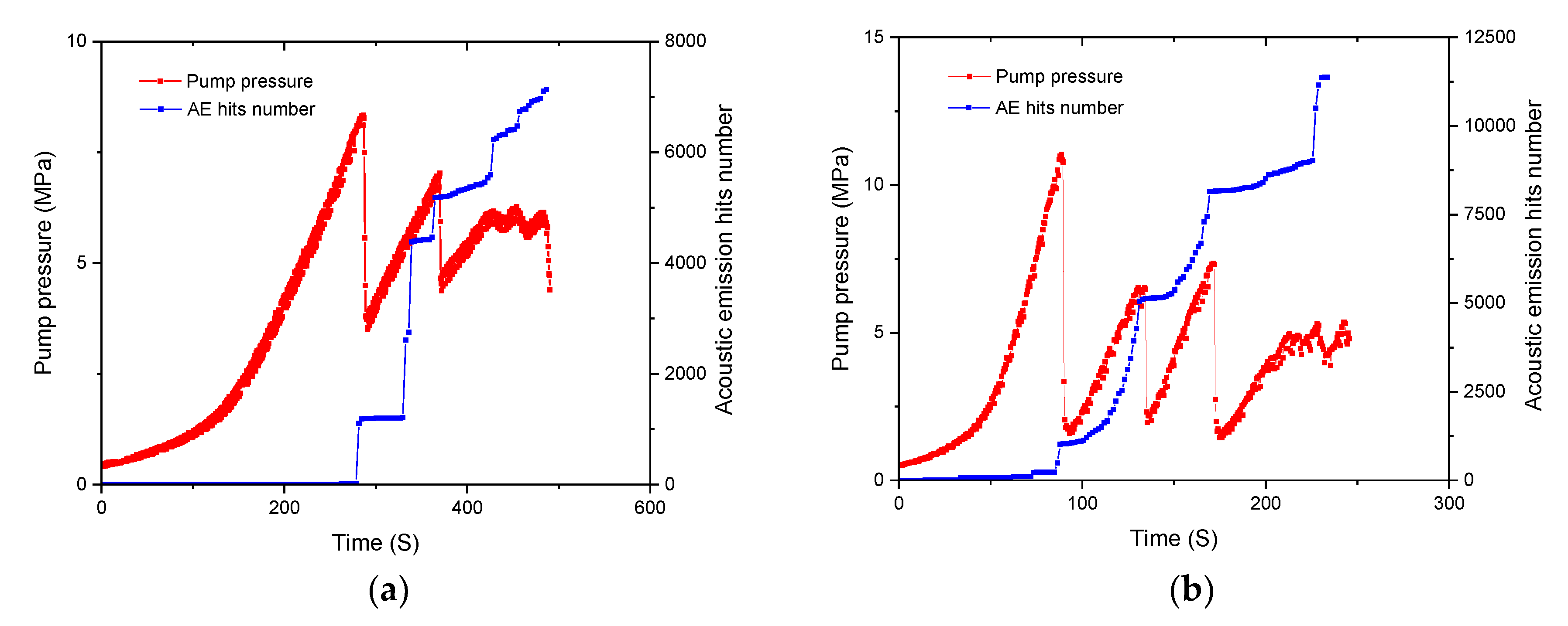
3.1. Fracturing Pump Pressure and AE Characteristics

In this study, the fracturing pressure and AE characteristics during the failure process of the samples were obtained, as shown in Figure 3. It can be seen that the characteristics of the fracturing pressure curves obtained with different fracturing fluids were significantly different. Figure 3a,b show that the slick water had a viscosity of 3.5 mPa·s when it was used as the fracturing fluid. The fracturing pressure had a relatively slow growth at the beginning of the fracturing fluid injection. This could be due to a small amount of air inside the simulated wellbore, which had compressibility. Then, with the injection of slick water, the fracturing pressure increased rapidly to reach the fracturing breakdown pressure and then dropped rapidly. With continued injection of fracturing fluid, the fracturing pressure continued to grow, which was lower than the initial fracturing breakdown pressure, and multiple rupture points were formed. Although the fracturing fractures formed stable migration channels, the injection volume was greater than the discharge of surface hydraulic fracturing cracks, and the fracturing pressure therefore continued to increase. In accordance with natural fractures or filled fractures, the fracturing pressure curve showed up and down pattern repeatedly. The severe fluctuations in the fracturing pressure curve indicated that a large number of original natural fractures or filled fractures were present in the specimens, which caused a certain amount of fracturing fluid loss in propagation.
In Figure 3a, it can be seen that when the fracturing fluid was injected at a constant rate of 0.02 mL/s, the fracturing breakdown pressure was 8.34 MPa, the fracturing pressure curve produced two significant drops, and 7137 AE hits was monitored within the sample. When the flow rate was 0.07 mL/s (Figure 3b), the fracturing breakdown pressure increased to 11.03 MPa, the fracturing pressure curve produced three significant drops, and the number of AE hits increased to 11,372. This indicated that the fracturing fracture under the condition of large pump flow rate was more severe.
In Figure 3c,d, it can be seen that when the fracturing fluid was guar gum, the viscosity reached 230 mPa·s. The fracturing pressure grew slowly at a standstill for long periods at the beginning of the fracturing fluid injection. Then, with the injection of guar gum, the fracturing pressure increased rapidly to reach the fracturing breakdown pressure and then dropped rapidly. Moreover, with continuing pumping fracturing fluid, the fracturing pressure no longer increased. This indicated that the main fracturing crack was formed in the sample and connected to the surface, forming a permeation channel.
To understand the effect of reactive acid fracturing fluid on the fracture morphology, two groups of fracturing experiments based on cross-linked acid and gelled acid were carried out. The viscosity of cross-linked acid was 150 mPa·s, and the viscosity of gelled acid was 80 mPa·s. These types of fracturing fluids are often used in reconstruction of carbonate reservoirs. As can be seen in Figure 3e–h, the fracturing pressure curve before breakdown was similar to that of guar gum. There was no obvious difference between the nonreactive fracturing fluid and the reactive acid fracturing fluid because the viscosities of these three fracturing fluids were relatively close. Under the condition of fracturing fluid with high viscosity, natural fractures or filled cracks in carbonate rock were difficult to detect. When acid fracturing fluid was injected into the specimen, it had less influence on the mechanical properties of carbonate rock in the confined space and in a short time. When the specimen was broken, the fracturing pressure dropped rapidly. The fracturing breakdown pressure usually showed that an obvious transverse main fracturing fracture had been formed and continued to pump fracturing fluid; the fracturing pressure no longer increased. The fracturing pressure curves of the two acid fracturing fluids showed the same trend. Under the condition of different flow rates, only the peak value of fracturing breakdown pressure changed.
In the fracturing test, a complete fracturing fluid injection pressure was obtained, and the whole evolution of AE hits was collected. Figure 3 illustrates the relationship between the fracturing fluid injection pressure and the number of AE hits. The AE hit characteristic had one thing in common for all the specimens, i.e., the AE activity was relatively low at the initial fracturing fluid injection stage, and increasing the fracturing pressure did not cause an increase in the number of AE hits. However, the AE activity increased rapidly at the breakdown peak of fracturing pressure. Differences in AE characteristic were apparent in the four fracturing fluids (slick water, guar gum, cross-linked acid, and gelled acid). When the fracturing pressure of slick water injection reached 8.34 MPa at the rate of 0.02 mL/s, a turning point appeared in the fracturing pressure curve, and at this moment, the number of AE hits showed a rapid increase (Figure 3a). This showed that the well hole ruptured or the first blasting cracks opened and burst, meaning the fracturing breakdown pressure of slick water was 8.34 MPa. With continuing injection of fracturing fluid, the impact of AE hits obviously increased with each drop of fracturing pressure. This proved that multiple fracturing cracks had formed by slick water fracturing. When guar gum was used as the fracturing fluid, the fracturing pressure was more than 75% of the breakdown pressure but less than the breakdown pressure peak (Figure 3c,d). The number of AE hits saw a minor increase, but it still remained relatively low until reaching the breakdown pressure. This observation indicated that a small number of microcracks, as well as energy release, was generated in the carbonate rocks prior to the breakdown pressure. The main reason for this was the interaction between high viscosity fracturing fluid and wellbore rock, which resulted in a small number of microcracks.
When cross-linked acid and gelled acid were used as the fracturing fluids, the number of AE hits was relatively low at the initial fracturing fluid injection stage. The AE activity increased rapidly at the fracturing pressure peak, and the fracturing pressure curve was similar to the first stage of slick water fracturing. The effect of acid and carbonate reaction on acoustic emission events was not obvious. These results implied that the type of fracturing fluid had little effect on the evolutionary characteristics of AE activity; this is because AE hits are mainly related to rupture energy.
The maximum cumulative AE hit by slick water fracturing was 10 times larger than that of other fracturing fluids. This was mainly due to the formation of multiple fractures in slick water fracturing, meaning the number of AE hits was large. This also indicated that more energy needed to be absorbed from the outside before the internal structure failure.

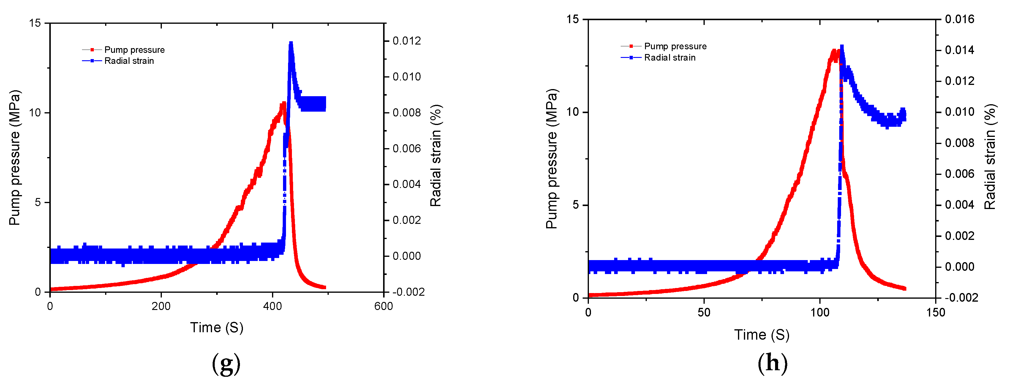
3.2. Fracturing Pump Pressure and Radial Strain

The deformation of rock under hydraulic fracturing can reflect changes in the internal structure and crack propagation. An earlier study on the influence of hydraulic fracturing on coal had found that the propagation of microcracks had an important influence on the deformation of coal [17]. However, in a preliminary study of hydraulic fracturing, it was difficult to capture the deformation behavior of rocks [18]. In this study, the radial strain gauge was installed on the circumference of the specimen, and the whole radial strain during fracturing fluid injection were obtained, as shown in Figure 4. It can be seen that the radial strain characteristic also had one thing in common for all specimens, i.e., the radial strain saw almost no change at the initial fracturing fluid injection stage, and increasing the fracturing pressure did not cause an increase in radial strain. In addition, the radial strain rapidly increased swelling at the fracturing breakdown pressure. When the fracturing pressure dropped, the radial strain decreased correspondingly. In a real situation, if accompanied by a continuous increase in the pressure of fracturing fluid in the wellbore, this will cause deformation of rock around the wellbore. However, as the diameter of the simulated wellbore was only 12 mm, the influence range of the radial deformation was generally 3–5 times the diameter of the wellbore. The radial strain gauge failed to effectively monitor the radial deformation during the stage of hydraulic fracturing pressure increase. When the macrofracture occurred due to hydraulic fracturing, the deformation caused an increase in the sample circumference, and a sudden change in radial strain occurred.
Differences in radial strain characteristics were apparent in the four fracturing fluids (slick water, guar gum, cross-linked acid, and gelled acid). As shown in Figure 5, the effect of fracturing fluid on the breakdown pressure was different. Under the same flow rate condition, the breakdown pressure was the lowest when slick water was the fracturing fluid. This showed that fracturing fluids with low viscosity could easily activate weakly natural fractures or filled fractures, leading to open microcracks, and could effectively reduce breakdown pressure.
When guar gum was used as the fracturing fluid, the fracturing breakdown pressure increased significantly. This indicated that when high viscosity fracturing fluid was used, it primarily formed a single transverse fracture with a larger fracture width. The same result was obtained from the change in radial strain of the specimen. When acid fluids were used as the fracturing fluid, the changes in breakdown pressure were similar. In a short period, the weakening effect of acid solution on the mechanical properties of carbonate rocks was not obvious. Especially in confined environments, the effect of acid–rock reaction will decrease correspondingly. The main feature was the effect of high viscosity on fracturing breakdown pressure.
Based on the fracturing results, it can be concluded that viscosity is an important factor affecting fracture morphology and width of carbonate specimens. Figure 6 shows the radial strain with different fracturing fluids and flow rates. Under the same conditions, the maximum changes in radial strain at the breakdown pressure point occurred when the fracturing fluid was guar gum. The radial strain change of guar gum was three times that of slick water, although the viscosity of cross-linked acid and gelled acid was 10 times larger than that of slick water. When the fracturing fluid was cross-linked acid or gelled acid, the changes in radial strain was a little larger than slick water and far less than guar gum. This was mainly due to the dissolution of wormhole after injecting acid fracturing fluid, meaning changes in radial strain were relatively low. Under the same fracturing fluid, the change in radial strain increased with the increase in flow rate. When the flow rate was 0.07 mL/s, the change in radial strain was about 1.5 times that of the flow rate of 0.02 mL/s. This indicates that when the fracturing fluid is injected with high flow rate, the width of the main fracturing is larger, and it would be easier to add proppant.

3.3. Failure Mode and CT Characteristic

The fracture patterns of carbonate rocks under different fracturing fluids after hydraulic fracturing are shown in Figure 7.
The fracture pattern characteristics also had one thing in common for all specimens, i.e., a main fracturing crack was formed along the direction of maximum principal stress. Fracturing fluid diffusion was observed along the fracturing cracks, and a stable seepage channel was formed. This was the main reason for the fracturing pressure no longer increasing when the pump pressure dropped. Differences in the fracture pattern characteristics were apparent in the four fracturing fluids. When slick water was used as the fracturing fluid, several secondary cracks intersecting with the main fracturing fracture were observed on the surface and inside the specimen, and more flow channels were produced. This indicates that slick water fracturing can open more weak surfaces and microcracks, which is one of the purposes of carbonate reservoir fracturing reconstruction. When guar gum was used as the fracturing fluid, only one main fracture was observed on the surface, and the fractures broke through the upper and lower ends of the specimen. The specimens were fractured, resulting in a simple fracture, and the fracture surface was fully opened. When gelled acid and cross-linked acids were used as the fracturing fluid, the fracture morphology obtained after fracturing was similar, and one main fracture was observed on the surface. However, the extension of the fracturing was mainly focused near the crack initiation parts. The crack expanded asymmetrically; the wormhole was dissolved to break through to the surface of the specimen, and the range of fracture reconstruction was effective. This shows that only using acid as fracturing fluid may not be effective.
As it was difficult to obtain clear fracture morphology by direct observation, high-energy CT scanning results were used to analyze the fracture characteristics for typical specimens of slick water and gelled acid fracturing. The fracture morphology after hydraulic fracturing using slick water is shown in Figure 8. The CT scanning images after hydraulic fracturing mainly showed two types of fracture morphology. One of them was along the direction of the maximum principal stress; the direction of the axis had a clear demarcation line, and one main fracturing crack was formed. A fracture with width of about 0.2 mm was formed when slick water was used as the fracturing fluid (Figure 8a,b). In addition to the main fracturing crack, there was also a natural weak surface in the nonaxial direction. The width of this fracture was very narrow, and the fracture interfaces were not clear, as shown in Figure 8c.
The fracture morphology after hydraulic fracturing using gelled acid as the fracturing fluid is shown in Figure 9. As can be seen, the fracture surfaces were asymmetrically distributed, and they were mainly on the side of the well axis. Due to the large crack opening and corrosion of fracture, the fracture interfaces were very obvious. After fracturing test, the residual acid reacted with carbonate rock and dissolved part of the calcite. The fracture surface was undulating and zigzag, and the width of the fracture was about 0.8 mm. This shows that the dissolution of gelled acid solution could increase the width of fracturing crack and improve the conductivity of carbonate reservoirs.

4. Discussion

For carbonate reservoirs with different reservoir characteristics and geological conditions, the fracturing fluid and fracturing technology used in carbonate reservoirs are different. For deep carbonate reservoirs with fracture development, it is not sufficient to open natural fracture or filled fracture by hydraulic fracturing. Therefore, it is necessary to explore the fracture expansion mode of fractured carbonate reservoirs. In this study, the effects of different reactive acid fracturing fluids and their combinations on the reconstruction volume of natural cracks were examined, and the relationship between fracturing cracks and fracturing fluids was clarified. Based on the results of this study, it is necessary to adopt different fracturing fluids and techniques according to the development of carbonate fractures. When the natural fractures or filled fractures in carbonate reservoirs near wellbore are relatively developed, slick water with low flow rate can be initially used to form complex fracturing cracks. Then, gelled acid can be injected into the fracturing cracks to dissolve the cracks in order to improve the conductivity of the carbonate reservoir. When natural fracture does not develop, in order to reduce the fracturing breakdown pressure, pretreatment with gelled acid can be used. On the one hand, this can weaken the mechanical properties of carbonate rock; on the other hand, it can form microcracks at the well wall. Then, slick water with low flow rate can be adopted to form a highly complex fracture network.

5. Conclusions

In this study, hydraulic fracturing experiments were carried out in the laboratory for carbonate outcrops. Four types of fracturing fluids were selected for the fracturing tests. Two kinds of acid fracturing fluids (cross-linked acid and gelled acid) and two nonreactive fracturing fluids (slick water and guar gum) were used. The effects of fracturing fluid, pump flow rate, and viscosity of fracturing fluid on the fracture morphology and fracturing pressure characteristics were explored. Some important observations are as follows:
(1)
For fractured carbonate reservoirs, different fracturing fluids had different fracturing capacities. Under the condition of same fracturing fluid, the pump flow rate mainly affected the fracturing breakdown pressure and had little effect on fracture morphology.
(2)
The viscosity of fracturing fluid had a significant effect on fracturing breakdown pressure. Under the same pump flow rate, the fracturing breakdown pressure of slick water was the lowest. The fracturing fluid with low viscosity could easily activate weakly natural fractures or filled fractures, leading to open microcracks, and could effectively reduce fracturing breakdown pressure. This was also helpful in increasing the complexity of fracturing fracture.
(3)
The fracturing pump pressure had a good correspondence with acoustic emission hits and changes in radial strain. Acoustic emission signals accompanied the initiation and propagation of pressure fractures in hydraulic fracturing. Large fracturing cracks caused abrupt changes in the radial strain of the specimen; for every drop of fracturing pressure, the AE hits and radial strain were mutated.
(4)
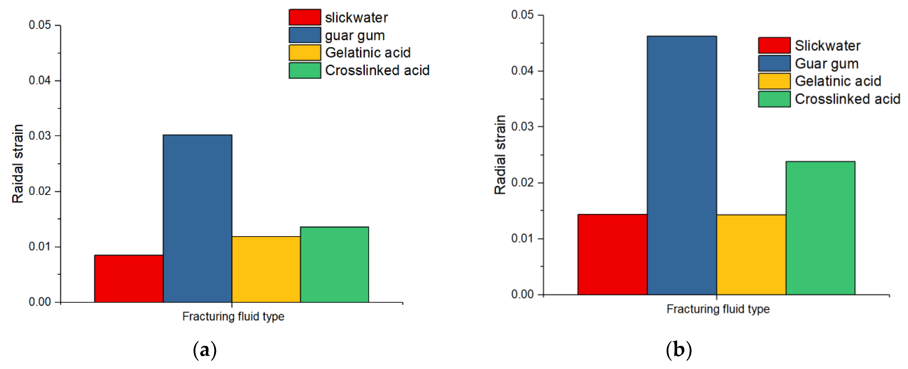
The width of the main fracturing fracture was affected by the viscosity and pump flow rate. Under the same conditions, the maximum changes in radial strain at the fracturing breakdown pressure point occurred when the fracturing fluid was guar gum.
(5)
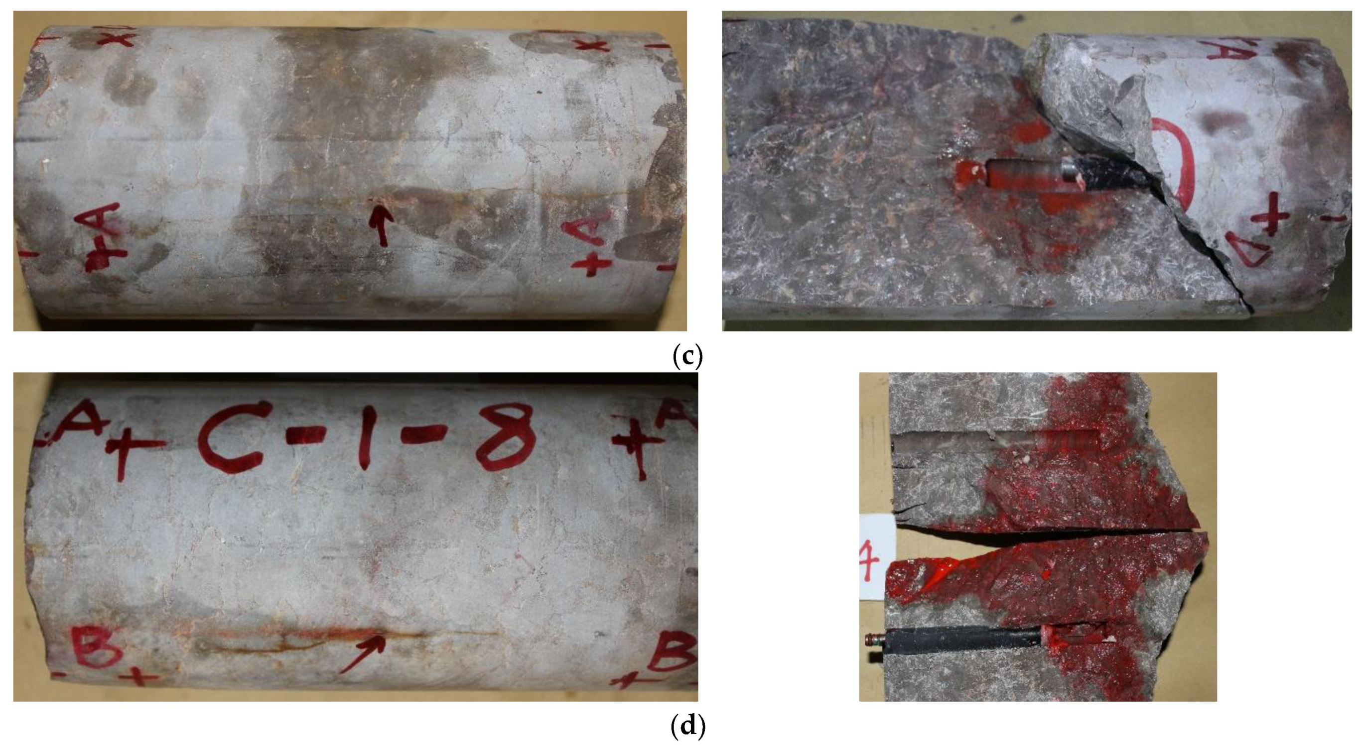
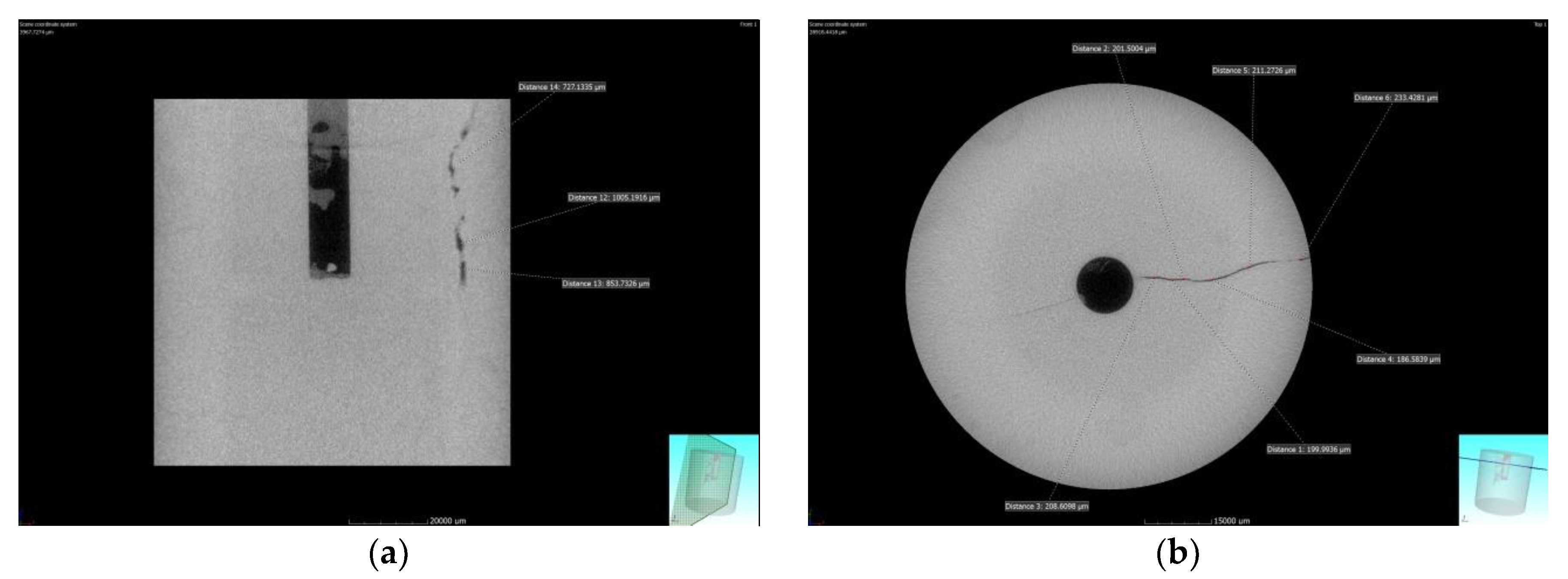
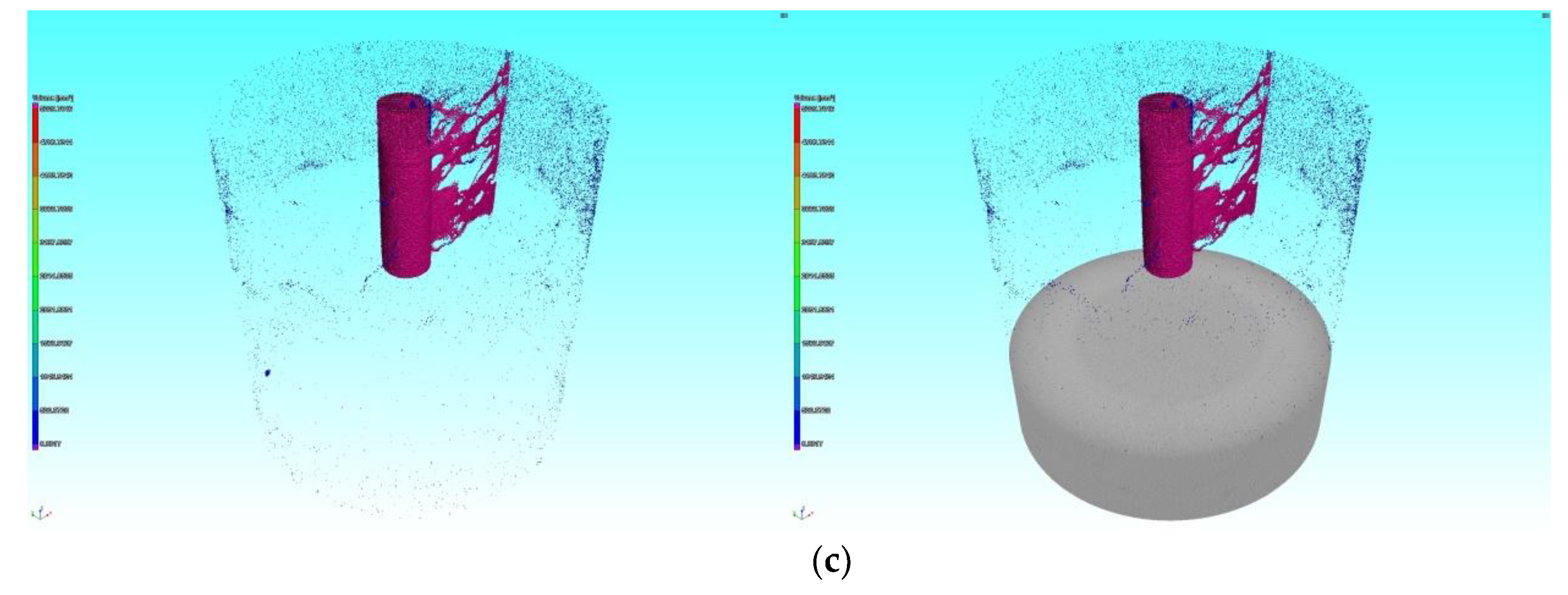
One main fracturing fracture was observed on the surface with gelled acid and cross-linked acid fracturing. The extension of the fracturing was mainly focused near the crack initiation parts. The crack expanded asymmetrically; the wormhole was dissolved to break through to the surface of the specimen.
(6)
Acid fracturing fluid had little effect on the fracturing pressure and fracture morphology during the fracturing process. However, the dissolution of gelled acid solution could increase the width of fracturing crack and improve the conductivity of carbonate reservoirs.

Author Contributions

Y.G. and X.C. designed the hydraulic fracturing tests methodology; C.Y. funding Acquisition; P.D. and J.Z. prepared the samples and carried out the hydraulic fracturing tests; L.W. analysis of test results.

Funding

The research was supported by National Natural Science Foundation of China (51574218), National Science and Technology Major Project of China (2017ZX05005-004, 2017ZX05036-003), and Research on Key Scientific and Technical Issues in Exploration and Development of Shale Gas (XDB10040200), CAS pilot project (B).

Conflicts of Interest

The authors declare no conflict of interest.

References

  1. Arthur, J.D.; Bohm, B.; Layne, M. Hydraulic fracturing considerations for natural gas wells of the Marcellus shale. In Proceedings of the Ground Water Protection Council, Cincinnati, OH, USA, 21–24 September 2008. [Google Scholar]
  2. Hou, P.; Gao, F.; Ju, Y. Experimental investigation on the failure and acoustic emission characteristics of shale, sandstone and coal under gas fracturing. J. Natural Gas Sci. Eng. 2016, 35, 211–223. [Google Scholar] [CrossRef]
  3. Du, C.Z. Study on Theoretics of Hydraulic Fracturing in Coal Bed and Its Applications. Ph.D. Thesis, China University of Mining and Technology, Xuzhou, China, 2008. [Google Scholar]
  4. Huang, B.; Liu, C.; Fu, J. Hydraulic fracturing after water pressure control blasting for increased fracturing. Int. J. Rock Mech. Min. Sci. 2011, 48, 976–983. [Google Scholar] [CrossRef]
  5. Chitrala, Y.; Moreno, C.; Sondergeld, C.; Rai, C. An experimental investigation into hydraulic fracture propagation under different applied stresses in tight sands using acoustic emissions. J. Pet. Sci. Eng. 2013, 108, 151–161. [Google Scholar] [CrossRef]
  6. Huang, B.X. Research on Theory and Application of Hydraulic Fracture Weakening for Coal–Rock Mass. Ph.D. Thesis, China University of Mining and Technology, Xuzhou, China, 2008. [Google Scholar]
  7. Bohloli, B.; de Pater, C.J. Experimental study on hydraulic fracturing of soft rocks: Influence of fluid rheology and confining stress. J. Pet. Sci. Eng. 2006, 53, 1–12. [Google Scholar] [CrossRef]
  8. Casas, L.A.; Miskimins, J.L.; Black, A.D.; Green, S.J. Laboratory hydraulic fracturing test on a rock with artificial discontinuities. In Proceedings of the SPE Annual Technical Conference and Exhibition, San Antonio, TX, USA, 24–27 September 2006. [Google Scholar]
  9. Zhou, J.; Jin, Y.; Chen, M. Experimental investigation of hydraulic fracturing in random natural fractured blocks. Int. J. Rock Mech. Min. Sci. 2010, 47, 1193–1199. [Google Scholar] [CrossRef]
  10. Matsunaga, I.; Kobayashit, H.; Sasaki, S.; Ishida, T. Studying Hydraulic Fracturing Mechanism by Laboratory Experiments with Acoustic Emission Monitoring. Int. J. Rock Mech. Min. Sci. Geomech. Abstr. 1993, 30, 909–912. [Google Scholar] [CrossRef]
  11. Guo, T.; Zhang, S.; Qu, Z.; Zhou, T. Experimental study of hydraulic fracturing for shale by stimulated reservoir volume. Fuel 2014, 128, 373–380. [Google Scholar] [CrossRef]
  12. Zhou, J.; Chen, M.; Jin, Y.; Zhang, G.Q. Experiment of propagation mechanism of hydraulic fracture in multi-fracture reservoir. J. China Univ. Petrol. (Ed. Nat. Sci.) 2008, 32, 51–54. [Google Scholar]
  13. Zhou, J.; Chen, M.; Jin, Y.; Zhang, G.Q. Analysis of fracture propagation behavior and fracture geometry using a tri-axial fracturing system in naturally fractured reservoirs. J. Rock Mech. Min. Sci. 2008, 45, 1143–1152. [Google Scholar] [CrossRef]
  14. Palchik, V. Mechanical Behavior of Carbonate Rocks at Crack Damage Stress Equal to Uniaxial Compressive Strength. Rock Mech. Rock Eng. 2010, 43, 497–503. [Google Scholar] [CrossRef]
  15. Fernø, M.A.; Haugen, Å.; Graue, A. Wettability effects on the matrix–fracture fluid transfer in fractured carbonate rocks. J. Pet. Sci. Eng. 2011, 77, 146–153. [Google Scholar] [CrossRef]
  16. Jian, Z.; Mian, C.; Yan, J. Experimental study on strength reduction effects of limestone near fracture area during acid fracturing. Chin. J. Rock Mech. Eng. 2007, 26, 206–1210. [Google Scholar]
  17. Deng, G.Z.; Wang, S.B.; Huang, B.X. Research on behavior character of crack development induced by hydraulic fracturing in coal-rockmass. Chin. J. Rock Mech. Eng. 2004, 23, 3489–3493. [Google Scholar]
  18. Chen, L.H.; Chen, W.C.; Chen, Y.C.; Benyamin, L.; Li, A.J. Investigation of hydraulic fracture propagation using a post-peak control system coupled with acoustic emission. Rock Mech. Rock Eng. 2015, 48, 1233–1248. [Google Scholar] [CrossRef]
Figure 1. Sample design for hydraulic fracturing: (a) Dimensions of sample; (b) manufactured sample.
Energies 11 03502 g001
Figure 2. Hydraulic fracturing test system: (a) Rock mechanic testing system; (b) fracturing fluid pump injection system; (c) acoustic emission (AE) system.
Energies 11 03502 g002
Figure 3. Relationship between fracturing pressure and AE characteristics with different fracturing fluids and pump flow rate: (a) C-2-7 slick water (0.02 mL/s); (b) C-2-8 slick water (0.07 mL/s); (c) C-2-3 guar gum (0.02 mL/s); (d) C-2-4 guar gum (0.07 mL/s); (e) C-1-1 cross-linked acid (0.02 mL/s); (f) C-1-2 cross-linked acid (0.07 mL/s); (g) C-1-7 gelled acid (0.02 mL/s); (h) C-1-8 gelled acid (0.07 mL/s).
Energies 11 03502 g003aEnergies 11 03502 g003b
Figure 4. Hydraulic fracturing pressure and deformation curve of carbonate rocks: (a) C-2-7 slick water (0.02 mL/s); (b) C-2-8 slick water (0.07 mL/s); (c) C-2-3 guar gum (0.02 mL/s); (d) C-2-4 guar gum (0.07 mL/s); (e) C-1-1 cross-linked acid (0.02 mL/s); (f) C-1-2 cross-linked acid (0.07 mL/s); (g) C-1-7 gelled acid (0.02 mL/s); (h) C-1-8 gelled acid (0.07 mL/s).
Energies 11 03502 g004aEnergies 11 03502 g004b
Figure 5. Rupture pressure with different fracturing fluids and flow rate: (a) 0.02 mL/s; (b) 0.07 mL/s.
Energies 11 03502 g005
Figure 6. Radial strain with different fracturing fluids and flow rate: (a) 0.02 mL/s; (b) 0.07 mL/s.
Energies 11 03502 g006
Figure 7. Failure modes with different fracturing fluid: (a) Slick water; (b) guar gum; (c) cross-linked; (d) gelled acid.
Energies 11 03502 g007aEnergies 11 03502 g007b
Figure 8. Fracture morphology after hydraulic fracturing of specimen using slick water: (a) CT scanning along the axis; (b) CT scanning perpendicular to the axis; (c) fracture spatial morphology.
Energies 11 03502 g008
Figure 9. Fracture morphology after hydraulic fracturing of specimen using gelled acid: (a) CT scanning along the axis; (b) CT scanning perpendicular to the axis; (c) fracture spatial morphology.
Energies 11 03502 g009aEnergies 11 03502 g009b
Table 1. Material parameters of carbonate used in triaxial fracturing tests.
Young’s Modulus/GPa35.59
Uniaxial compressive strength/MPa129.34
Tensile strength/MPa8.46
Cohesive force/MPa27.35
Friction angle38.12
Porosity (%)3.5
Permeability (Darcy)0.004
Poisson’s ratio0.192
The average velocity/m/s5722
Table 2. Overview of the fracturing test results.
Sample No.Fracturing FluidPump Flow Rate
(mL/s)
σv
(MPa)
σH = σh
(MPa)
Rupture
Pressure (MPa)
C-2-7Slick water0.022508.34
C-2-8Slick water0.0725011.03
C-2-3Guar gum0.0225010.31
C-2-4Guar gum0.0725012.19
C-1-1Cross-linked acid0.0225010.56
C-1-2Cross-linked acid0.0725013.34
C-1-7Gelled acid0.0225010.36
C-1-8Gelled acid0.0725013.04

